Tripp Lite SMX2200XLRT2U User manual
- Type
- User manual

Owner’s Manual
1111 W. 35th Street Chicago, IL 60609 USA
Customer Support: (773) 869-1234 • www.tripplite.com
Important Safety Instructions
2
Mounting
3
Quick Installation
5
Basic Operation
7
Storage and Service
11
Español
Copyright ©2006 Tripp Lite. All rights reserved. SmartPro
®
is a trademark of Tripp Lite
SmartPro
®
Intelligent, Line-Interactive UPS System
• 220/230/240V Sine Wave Input/Output • Extended Runtime Capability
Model: SMX2200XLRT2U
Not suitable for mobile applications
13
Battery Replacement
12
Français
25
Optional Installation
6
Deutsch
37
PyccŞèé
49
200510005 93-2445 SmartOnline 1phase OM.qxd 4/14/2006 4:05 PM Page 1

2
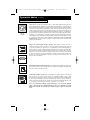
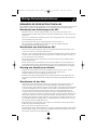
Important Safety Instructions
SAVE THESE INSTRUCTIONS
This manual contains important instructions that should be followed during the installation, operation
and storage of all Tripp Lite UPS Systems. Failure to heed these warnings will void your warranty.
UPS Location Warnings
• Use caution when lifting UPS. Because of the considerable weight of all Rackmount UPS
systems, at least two people should assist in lifting and installing them.
• Install your UPS indoors, away from excess moisture or heat, dust or direct sunlight.
• For best performance, the ambient temperature near your UPS should be between 0° C and
40° C (between 32° F and 104° F).
• Leave adequate space around all sides of the UPS for proper ventilation. Do not obstruct its
vents or fan openings.
UPS Connection Warnings
• The UPS contains its own energy source (battery). The output terminals may be live even
when the UPS is not connected to an AC supply.
• Connect your UPS to a properly grounded AC power outlet. Do not modify the UPS’s plug
in a way that would eliminate the UPS’s connection to ground. Do not use adapters that
eliminate the UPS’s connection to ground.
• Do not plug your UPS into itself; this will damage the UPS and void your warranty.
• If you are connecting your UPS to a motor-powered AC generator, the generator must provide
filtered, frequency-regulated computer-grade output. Connecting your UPS to a generator will
void its Ultimate Lifetime Insurance.
Equipment Connection Warnings
• Do not use Tripp Lite UPS Systems for life support applications in which a malfunction or
failure of a Tripp Lite UPS System could cause failure or significantly alter the performance
of a life-support device.
• Do not connect surge suppressors or extension cords to the output of your UPS. This might
overload the UPS and will void the surge suppressor and UPS warranties.
Battery Warnings
• Batteries can present a risk of electrical shock and burn from high short-circuit current.
Observe proper precautions. Do not dispose of the batteries in a fire. Do not open the UPS or
batteries. Do not short or bridge the battery terminals with any object. Unplug and turn off the
UPS before performing battery replacement. Use tools with insulated handles. There are no
user-serviceable parts inside the UPS. Battery replacement should be performed only by
authorized service personnel using the same number and type of batteries (sealed Lead-Acid).
The batteries are recyclable. Refer to your local codes for disposal requirements. Tripp Lite
offers a complete line of UPS System Replacement Battery Cartridges (R.B.C.). Visit Tripp
Lite on the Web at www.tripplite.com to locate the specific replacement battery for your UPS.
• During hot-swap battery replacement, the UPS will not provide backup power in the event of
a blackout or other power interruptions.
• Do not operate UPS without batteries.
• When adding external battery packs to select models with external battery pack connectors,
connect only Tripp Lite-recommended battery packs of the correct voltage and type. Do not
connect or disconnect battery packs when the UPS is operating on battery power.
200510005 93-2445 SmartOnline 1phase OM.qxd 4/14/2006 4:05 PM Page 2

3
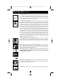
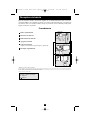
Mounting (Rack)
Mount your equipment in either a 4-post or 2-post rack or rack enclosure. The user must determine
the fitness of hardware and procedures before mounting. If hardware and procedures are not suit-
able for your application, contact the manufacturer of your rack or rack enclosure. The procedures
described in this manual are for common rack and rack enclosure types and may not be appropriate
for all applications.
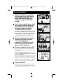
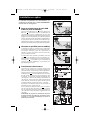
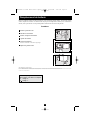
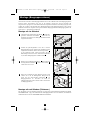
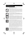
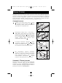
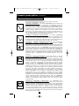
4-Post Mounting
All UPS models include hardware required to mount in a 4-post rack. Select models include an
adjustable rackmount shelf kit to provide additional support. If your UPS model does not
include
an adjustable rackmount shelf kit, skip steps 1 and 2.
Connect the two segments of each shelf using the
included screws and nuts . Leave the screws slightly
loose so that the shelves can be adjusted in the next step.
Adjust each shelf to fit your rack, then mount them in
the lowest available space of your rack with the
screws, nuts and washers provided . Note that the
support ledges should face inward. Tighten the screws
that connect the shelf segments .
Attach mounting ears to the front mounting holes
of your equipment using the screws provided .
The ears should face forward.
Using an assistant if necessary, lift your equipment
and slide it onto the mounting shelves. Attach your
equipment to the rack by using the appropriate
hardware through its mounting ears and into the
rack rails.
G
F
E
D
B
C
B
A
1
2
3
A
B
C
B
E
D
F
G
1
2
3
4
4
2-Post (Telecom) Mounting
Two-post mounting will require a Tripp Lite 2-Post Rackmount Installation Kit (Model
2POSTRMKITWM, sold separately). For detailed installation procedures, see the 2POSTRMK-
ITWM Owner's Manual.
200510005 93-2445 SmartOnline 1phase OM.qxd 4/14/2006 4:05 PM Page 3

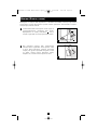
Mounting (Tower)
4
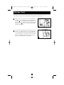
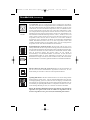
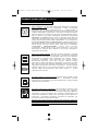
Mount all UPS models in an upright, tower position using included hardware. The user must deter-
mine the fitness of hardware and procedures before mounting.
Stand your UPS on its side with the LED/Control panel
at the top. Attach one rack mounting ear to each side
of the UPS using included screws . Attach the rack
mounting ears to the floor with user-supplied
hardware.
Rotate the LED/Control panel to view it easier while
the UPS is tower mounted. Insert a small screwdriver,
or other tool, in the slots on either side of the panel.
Pop the panel out; rotate it; and pop the panel back in
place.
B
A
A
B
1
2
1
2
200510005 93-2445 SmartOnline 1phase OM.qxd 4/14/2006 4:05 PM Page 4

5
BATTERIES
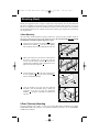
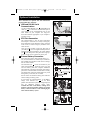
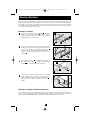
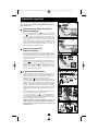
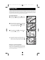
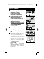
Quick Installation
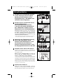
With the UPS disconnected from
utility power, use a small tool to
set the Voltage Dip Switches to
match your input voltage. (All
models are preset to the 230V
setting.)
Insert a user-supplied power cord
(with country-specific plug) into
the UPS System's IEC-320-C20
AC input receptacle. Plug the
cord into an AC wall outlet.*
NOTE! after you plug the UPS into a live AC outlet,
the UPS (in “Standby” mode) will automatically
charge its batteries,** but will not supply power to
its outlets until it is turned ON (see Step 3 below).
* See Specifications for circuit amperage requirements.
** The BATTERY CHARGE LED will be the only LED illuminated.
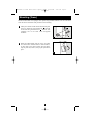
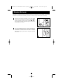
Find one of the power cords that
came with the UPS. Insert the
cord’s female plug into
computer’s AC input. Insert the
cord’s male plug into any UPS
female output receptacle.
Plug your equipment into the UPS.*
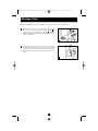
Plug your equipment into the UPS. Repeat Step 3
above using the additional power cord(s) that came
with the UPS.
Note: Additional interconnection cords (C13 to
C14) are available from Tripp Lite. Call 773-869-
1234 (Part # P004-006).
* Your UPS is designed to support computer equipment only. You will
overload the UPS if the total VA ratings for all the equipment you
connect exceeds UPS output capacity. To find your equipment’s VA
ratings, look on their nameplates. If the equipment is listed in amps,
multiply the number of amps by 240 to determine VA. (Example:
1 amp × 240 = 240 VA). If you are unsure if you have overloaded your
UPS's outlets, see “OUTPUT LOAD LEVEL” LED description.
Turn the UPS ON.
Press and hold the “ON/OFF/STANDBY” button for
one second. The alarm will beep once briefly after one
second has passed. Release the button.
1
1
2
5
3
4
5
2
3
4
200510005 93-2445 SmartOnline 1phase OM.qxd 4/14/2006 4:05 PM Page 5

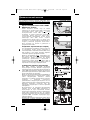
Optional Installation
These connections are optional. Your UPS will function
properly without these connections.
USB and RS-232 Serial
Communications
Use the included USB cable (see ) and/or DB9 serial
cable (see ) to connect the communication port on
your computer to the communication port of your
UPS. Install on your computer the Tripp Lite
PowerAlert Software appropriate to your computer’s
operating system.
EPO Port Connection
This optional feature is only for those applications
which require connection to a facility’s Emergency
Power Off (EPO) circuit. When the UPS is connected
to this circuit, it enables emergency shutdown of the
UPS’s inverter.
Using the cable provided, connect the EPO port of
your UPS (see ) to a user-supplied normally closed or
normally open switch according to the circuit diagram
(see ). The EPO port is not a phone line surge sup-
pressor; do not connect a phone line to this port.
External Battery Connection
Your UPS comes with a robust internal battery sys-
tem; external batteries are needed only to extend run-
time. Adding external batteries will increase recharge
time as well as runtime.
The illustration (see ) shows the location of your
UPS’s External Battery Connector, where you will
insert the battery pack cable. Complete installation
instructions for your battery pack appear in the battery
pack owner’s manual. Make sure that cables are fully
inserted into their connectors. Small sparks may result
during battery connection; this is normal.
Do not connect or disconnect battery packs when the
UPS is running on battery power.
If you connect any external batteries, set the Battery
Charge Level Switches (see ) to the down
position. This will increase your UPS’s charger output so
that the additional batteries charge faster.
Caution! DO NOT set the Battery Charge Level
Switches to the down position without an external
battery connected. There is a risk of damaging the
UPS’s internal battery system.
3b
3a
2b
2a
1b
1a
4-5
6
1b
1a
2a
2b
3a
1
2
3
EXTERNAL
BATTERIES
3b
200510005 93-2445 SmartOnline 1phase OM.qxd 4/14/2006 4:05 PM Page 6

7
“ON/OFF/STANDBY” Button
• To turn the UPS ON: with the UPS plugged into a live AC wall outlet*, press
and hold the “ON/OFF/STANDBY” button for one second.** Release the
button. If utility power is absent, you can “cold-start” the UPS (i.e.: turn it ON
and supply power for a limited time from its batteries***) by pressing and
holding the “ON/OFF/STANDBY” button for one second.**
• To turn the UPS OFF: with the UPS ON and receiving utility power, press
and hold the “ON/OFF/STANDBY” button for one second.** Then unplug
the UPS from the wall outlet. The UPS will be completely OFF.
* After you plug the UPS into a live AC outlet, the UPS (in ”Standby” mode) will automatically charge
its batteries, but will not supply power to its outlets until it is turned ON. ** The alarm will beep once
briefly after the indicated interval has passed. *** If fully charged.
“MUTE/TEST” Button
To Silence (or “Mute”) UPS Alarms: briefly press and release the
MUTE/TEST button.*
To Run a Self-Test: with your UPS plugged in and turned ON, press and hold
the MUTE/TEST button. Continue holding the button until the alarm beeps sev-
eral times and the UPS performs a self test. See “Results of a Self-Test” below.
Note: you can leave connected equipment on during a self-test. Your UPS, how-
ever, will not perform a self-test if the UPS is not turned on (see
“ON/OFF/STANDBY” Button description).
CAUTION! Do not unplug your UPS to test its batteries. This will remove
safe electrical grounding and may introduce a damaging surge into your
network connections.
Results of a Self-Test: The test will last approximately 10 seconds as the
UPS switches to battery to test its load capacity and battery charge.
• If the “OUTPUT LOAD LEVEL” LED remains lit red and the alarm
continues to sound after the test, the UPS’s outlets are overloaded. To
clear the overload, unplug some of your equipment and run the self-test
repeatedly until the “OUTPUT LOAD LEVEL” LED is no longer lit red
and the alarm is no longer sounding.
CAUTION! Any overload that is not corrected by the user immedi-
ately following a self-test may cause the UPS to shut down and cease
supplying output power in the event of a blackout or brownout.
• If the “BATTERY WARNING” LED remains lit and the alarm continues
to sound after the test, the UPS batteries need to be recharged or
replaced. Allow the UPS to recharge continuously for 12 hours, and
repeat the self-test. If the LED remains lit, contact Tripp Lite for service.
If your UPS requires battery replacement, visit www.tripplite.com to
locate the specific Tripp Lite replacement battery for your UPS.
Basic Operation
Buttons (Front Panel)
200510005 93-2445 SmartOnline 1phase OM.qxd 4/14/2006 4:05 PM Page 7

Basic Operation
continued
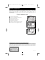
Indicator Lights (Front Panel)
All Indicator Light descriptions apply when the UPS is plugged into a wall
outlet and turned ON.
“POWER” LED: this green LED lights continuously when the UPS is ON and
supplying connected equipment with AC power from a utility source. The LED
flashes and an alarm sounds (4 short beeps followed by a pause) to indicate the
UPS is operating from its internal batteries during a blackout or severe
brownout. If the blackout or severe brownout is prolonged, you should save
files and shut down your equipment since internal battery power will eventual-
ly be depleted. See “BATTERY CHARGE” LED description below.
“VOLTAGE CORRECTION” LED: this green LED lights continuously
whenever the UPS is automatically correcting high or low AC voltage on the
utility line without the assistance of battery power. The UPS will also emit a
slight clicking noise. These are normal, automatic operations of the UPS, no
action is required on your part.
“OUTPUT LOAD LEVEL” LED: this multicolored LED indicates the
approximate electrical load of equipment connected to the UPS's AC outlets. It
will turn from green (light load) to yellow (medium load) to red (overload). If
the LED is red (either illuminated continuously or flashing), clear the overload
immediately by unplugging some of your equipment from the outlets until the
LED changes from red to yellow (or green). CAUTION! Any overload that is
not corrected by the user immediately may cause the UPS to shut down and
cease supplying output power in the event of a blackout or brownout.
“BATTERY CHARGE” LED: when the UPS is operating from utility power,
this LED indicates the approximate charge state of the UPS's internal batteries:
red indicates the batteries are beginning to charge; yellow indicates the batter-
ies are roughly midway through charging; and green indicates the batteries are
fully charged. When the UPS is operating from battery power during a blackout
or severe brownout, this LED indicates the approximate amount of energy
(ultimately affecting runtime) which the UPS’s batteries will provide: red indi-
cates a low level of energy; yellow indicates a medium level of energy; and
green indicates a high level of energy. Since the runtime performance of all UPS
batteries will gradually deplete over time, it is recommended that you periodi-
cally perform a self-test (see MUTE/TEST Button description) to determine the
energy level of your UPS batteries BEFORE a blackout or severe brownout
occurs. During a prolonged blackout or severe brownout, you should save files
and shut down your equipment since battery power will eventually be depleted.
When the LED turns red and an alarm sounds continuously, it indicates the
UPS's batteries are nearly out of power and UPS shut down is imminent.
“BATTERY WARNING” LED: this LED lights red and an alarm sounds
intermittently after you initiate a self test (See “MUTE/TEST” Button descrip-
tion) to indicate the UPS batteries need to be recharged or replaced. Allow the
UPS to recharge continuously for 12 hours, and repeat the self-test. If the LED
continues to light, contact Tripp Lite for service. If your UPS requires battery
replacement, visit www.tripplite.com to locate the specific Tripp Lite replace-
ment battery for your UPS.
8
200510005 93-2445 SmartOnline 1phase OM.qxd 4/14/2006 4:05 PM Page 8

9
Basic Operation
continued
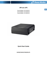
Other UPS Features (Rear Panel)
AC Receptacles: Your UPS features IEC320-C13 outlets. These output
receptacles provide your connected equipment with AC line power during
normal operation and battery power during blackouts and brownouts. The UPS
protects equipment connected to these receptacles against damaging surges and
line noise. If you have a serial or USB connection to your UPS, you can remote-
ly reboot connected equipment by turning individually controllable receptacles
OFF and ON using Tripp Lite's PowerAlert Software. Three receptacles,
labeled LOAD 1, LOAD 2 and LOAD 3, are individually controllable and may
be remotely switched OFF and ON using PowerAlert Software without
interrupting power to equipment connected to other outlets. Outlets labeled
UNSWITCHED may not be remotely turned off. Unswitched outlets can only
be turned off by turning off all output receptacles. See software instructions for
details.
Communications Ports (USB or RS-232): These ports connect your UPS to
any workstation or server. Use with Tripp Lite’s PowerAlert Software and
included cables to enable your computer to automatically save open files and
shut down equipment during a blackout. Also use PowerAlert Software to mon-
itor a wide variety of AC line power and UPS operating conditions. Consult
your PowerAlert Software manual or contact Tripp Lite Customer Support for
more information. See “USB and RS-232 Serial Communications” in the
“Optional Installation” section for installation instructions.
EPO (Emergency Power Off) Port: Your UPS features a EPO port that may
be used to connect the UPS to a contact closure switch to enable emergency
inverter shutdown. See Optional Installation.
Voltage DIP Switches: These switches enable the UPS to be set to match
actual input voltage. If the Voltage DIP Switches are set above or below input
voltage, the UPS will treat the input as a continuous overvoltage or undervolt-
age condition, and will automatically adjust input voltage to match the Voltage
DIP Switch setting. This will cause constant, unnecessary wear on the UPS.
Note: The Voltage DIP Switches must be set with the UPS turned OFF and
disconnected from utility power. If the switches are set while the UPS is
connected to utility power, the setting will not take effect.
IEC320-
C13/230V
NO EXTERNAL
BATTERIES
EXTERNAL
BATTERIES
200510005 93-2445 SmartOnline 1phase OM.qxd 4/14/2006 4:05 PM Page 9

Basic Operation
continued
Accessory Slot: Remove the small cover panel from this slot to install option-
al accessories to remotely monitor and control your UPS. Refer to your acces-
sory’s manual for installation instructions. Contact Tripp Lite Customer Support
at (773) 869-1234 for more information, including a list of available SNMP,
network management and connectivity products.
Power Sensitivity Adjustment: This dial is normally set fully counter-clock-
wise, which enables the UPS to provide maximum protection against waveform
distortions in its AC input. When such distortion occurs, the UPS will normal-
ly switch to providing sine wave power from its battery reserves for as long as
the distortion is present. In areas with poor utility power or where the UPS’s
input power comes from a backup generator, chronic waveform distortion could
cause the UPS to switch to battery too frequently, draining its battery reserves.
You may be able to reduce how often your UPS switches to battery due to mod-
erate waveform distortion by experimenting with different settings for this dial.
As the dial is turned clockwise, the UPS becomes more tolerant of variations in
its input power’s AC waveform. NOTE: The further the dial is adjusted clock-
wise, the greater the degree of waveform distortion the UPS will allow to pass
to connected equipment. When experimenting with different settings for this
dial, operate connected equipment in a safe test mode so that the effect on the
equipment of any waveform distortions in the UPS’s output can be evaluated
without disrupting critical operations.
External Battery Connector (Select Models Only): Use to connect Tripp Lite
external battery packs for additional runtime. Refer to instructions available
with the battery pack for complete connection information and safety warnings.
Battery Charge Level Switches (Select Models Only): Controls the UPS
system’s battery charge rate. If you connect any external batteries, set the Battery
Charge Level Switch to the down position. This will increase your UPS's charger
output so the additional batteries charge faster.
CAUTION! DO NOT set the Battery Charge Level Switches to the down
position without an external battery connected. There is a risk of damaging the
UPS’s internal battery system.
Input Breaker(s) (all models): Protect your electrical circuit from overcurrent
draw from the UPS load. If these breakers trip, remove some of the load, then
reset them by pressing the breaker(s) in.
Ground Screw: Use this to connect any equipment that requires a chassis ground.
10
Charge Rate Setting
(when External
Batteries ar
e con-
nected)
Charge Rate Setting
(when External
Batteries ar
e not
connected)
200510005 93-2445 SmartOnline 1phase OM.qxd 4/14/2006 4:05 PM Page 10

11
Storage and Service
Storage
Before storing your UPS, turn it completely OFF: with the UPS ON and receiving utility power,
press and hold the “ON/OFF/STANDBY” button for one second (an alarm will beep once briefly
after the interval has passed); then, unplug the UPS from the wall outlet. If you store your UPS for
an extended period of time, recharge the UPS batteries once every three months: plug the UPS into
a wall outlet; allow it to charge for 12 hours; and then unplug it and place it back in storage. Note:
after you plug the UPS in, it will automatically begin charging its batteries; however, it will not sup-
ply power to its outlets (see Quick Installation section). If you leave your UPS batteries discharged
for an extended period of time, they will suffer a permanent loss of capacity.
Service
Before returning your UPS for service, follow these steps:
1. Review the installation and operation instructions in this manual to ensure that the service
problem does not originate from a misreading of the instructions. Also, check that the UPS
System’s circuit breaker(s) are not tripped. This is the most common cause of service inquiries
which can be easily remedied by following the resetting instructions in this manual.
2. If the problem continues, do not contact or return the UPS to the dealer. Instead, call Tripp Lite
at (773) 869-1233. A service technician will ask for the UPS's model number, serial number
and purchase date and will attempt to correct the problem over the phone.
3. If the problem requires service, the technician will issue you a Returned Material Authorization
(RMA) number, which is required for service. If you require packaging, the technician can
arrange to send you proper packaging. Securely pack the UPS to avoid damage during ship-
ping. Do not use Styrofoam beads for packaging. Any damages (direct, indirect, special, inci-
dental or consequential) to the UPS incurred during shipment to Tripp Lite or an authorized
Tripp Lite service center is not covered under warranty. UPS Systems shipped to Tripp Lite or
an authorized Tripp Lite service center must have transportation charges prepaid. Mark the
RMA number on the outside of the package. If the UPS System is within the 2-year warranty
period, enclose a copy of your sales receipt. Return the UPS for service using an insured car-
rier to the address given to you by the Tripp Lite service technician.
200510005 93-2445 SmartOnline 1phase OM.qxd 4/14/2006 4:05 PM Page 11

12
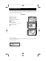
Battery Replacement
Regulatory Compliance Identification Numbers
For the purpose of regulatory compliance certifications and identification, your Tripp Lite product has been assigned a unique series number. The series number can be found on the product name-
plate label, along with all required approval markings and information. When requesting compliance information for this product, always refer to the series number. The series number should not be
confused with the marking name or model number of the product.
This product designed and engineered in the USA.
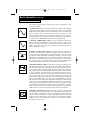
Note on Labeling
Two symbols are used on the label.
V~ : AC Voltage
V : DC Voltage
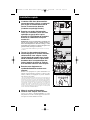
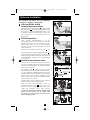
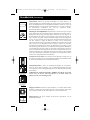
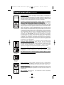
Under normal conditions, the original batteries in your UPS will last many years. See Safety
section before replacing batteries. The batteries are designed for hot-swap replacement (i.e. leaving the
UPS in ON mode), but some qualified service personnel may wish to put the UPS in the OFF mode
and disconnect equipment before proceeding.
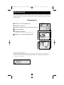
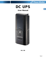
Procedure
Remove Front Panel
Disconnect Batteries
Remove/Dispose of Batteries
Add Batteries
Connect Batteries
Attach connectors: black-to-black and red-to-red.
Replace Front Panel
6
5
4
3
2
1
S
MART
P
RO
®
UPS
1
6
2
5
3
4
200510005 93-2445 SmartOnline 1phase OM.qxd 4/14/2006 4:05 PM Page 12
Page is loading ...
Page is loading ...
Page is loading ...
Page is loading ...
Page is loading ...
Page is loading ...
Page is loading ...
Page is loading ...
Page is loading ...
Page is loading ...
Page is loading ...
Page is loading ...
Page is loading ...
Page is loading ...
Page is loading ...
Page is loading ...
Page is loading ...
Page is loading ...
Page is loading ...
Page is loading ...
Page is loading ...
Page is loading ...
Page is loading ...
Page is loading ...
Page is loading ...
Page is loading ...
Page is loading ...
Page is loading ...
Page is loading ...
Page is loading ...
Page is loading ...
Page is loading ...
Page is loading ...
Page is loading ...
Page is loading ...
Page is loading ...
Page is loading ...
Page is loading ...
Page is loading ...
Page is loading ...
Page is loading ...
Page is loading ...
Page is loading ...
Page is loading ...
Page is loading ...
Page is loading ...
Page is loading ...
Page is loading ...
-
 1
1
-
 2
2
-
 3
3
-
 4
4
-
 5
5
-
 6
6
-
 7
7
-
 8
8
-
 9
9
-
 10
10
-
 11
11
-
 12
12
-
 13
13
-
 14
14
-
 15
15
-
 16
16
-
 17
17
-
 18
18
-
 19
19
-
 20
20
-
 21
21
-
 22
22
-
 23
23
-
 24
24
-
 25
25
-
 26
26
-
 27
27
-
 28
28
-
 29
29
-
 30
30
-
 31
31
-
 32
32
-
 33
33
-
 34
34
-
 35
35
-
 36
36
-
 37
37
-
 38
38
-
 39
39
-
 40
40
-
 41
41
-
 42
42
-
 43
43
-
 44
44
-
 45
45
-
 46
46
-
 47
47
-
 48
48
-
 49
49
-
 50
50
-
 51
51
-
 52
52
-
 53
53
-
 54
54
-
 55
55
-
 56
56
-
 57
57
-
 58
58
-
 59
59
-
 60
60


Tripp Lite SMX2200XLRT2U User manual
- Type
- User manual
Ask a question and I''ll find the answer in the document
Finding information in a document is now easier with AI
in other languages
Related papers
-
Tripp Lite 120V Input User manual
-
-
-
Tripp Lite SMART700DV Owner's manual
-
-
-
-
Tripp Lite 2POSTRMKITWM User manual
-
-
Other documents
-
SECOMP ProSecure II 1500 RM2U User manual
-
BlueWalker VI 600 SW Specification
-
 BlueWalker 10120404 Datasheet
-
Riello ID 60 Specification
-
Roland FR-3x Owner's manual
-
Memorex MP3112 User manual
-
 PowerWalker DC UPS 12V Owner's manual
-
Allen-Bradley 1609-P10000E User manual
-
Middle Atlantic Products UPS-OL1500R User manual
-

