Page is loading ...

3452535348
¤
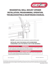
Included Wall Control MUST be installed prior to operation of this Garage
Door Operator
Safe-T-Beam
®
Safety Reverse System Must be installed to close door
SAVE THIS MANUAL FOR FUTURE REFERENCE
NOTE: Your Residential Operator comes with a Rail Assembly which is
standard for up to a 7 foot 6 inch high door. An extension kit for an 8 foot
high door is available.
®
®
For Answers and Assistance:
1.800.354.3643
or visit www.geniecompany.com
Series
GCG
, PCG, H
Includes Remote Control
and SERIES II Electronics
Garage Door
Operator

6
To avoid damage to your door and/or
operator, make sure you disable any door
locks prior to installing your operator
.
2
PRE-INSTALLATION CHECK LIST
FOR HELP-1.800.354.3643 OR GENIECOMPANY.COM
Things to consider if you are planning to do-it-yourself.
In many cases you will be replacing an existing door operator with a new one, however, if this
will be the first operator installed there are some pre-installation issues which need to be
addressed. They are as follows:
The Genie Company recommends that you read and fully understand all
information and instructions contained herein before choosing a Do-it-yourself
installation. Any questions should be directed to the Genie Company or an authorized
Genie Dealer.
1
Check your ceiling where the power
head of your new unit will be mounted.
Plan how you will be mounting the power head.
It is possible that ceiling joists may not be in the
position needed with respect to the garage door
operator. It may be necessary to add an
additional bracket and
fasteners (not included
with your new door operator kit).
2
Check the wall directly above the garage
door
. The door operator s header bracket
must be securely fastened to this wall. Insure
that the structure will provide a strong mounting
location.
3
Check to see if the mounting location
for the Safe-T-Beam
®
System STB is
clear from obstruction and has a wood
surface available for attaching the STB
brackets
. The brackets may be attached to
concrete if necessary but extra tools and special
fasteners (not supplied) will be required.
NOTE: 1-1/2" STB bracket adapters are
available through your local Genie Dealer.
4
Is your garage door made of
light-weight steel, aluminum, fiberglass
or glass panels
? Additional support bracing
must be added to these type doors. If this is the
case, please contact the door distributor or
manufacturer so that they can furnish you with a
bracing kit.
7
Insure that your door is properly balanced
and moving freely. SEE WARNING BELOW.
If your door sticks, binds, or is out of
balance, have it adjusted by a professional.
Door springs, cables, pulleys, brackets and
associated hardware are under extreme
tension and can cause serious injury or
death.
WARNING
(
The issue numbers below refer to the circled numbers in the illustrations on page 3.
)
8
(NOT SHOWN) If your garage does not have
a separate entry door, you should consider
an emergency release kit
(
GER-2
)
for installation on
your garage door. See page B at the center of this
manual.
DO NOT USE AN EXTENSION CORD!
Extension cords can cause dangerous
overheating conditions.
DO NOT USE A PORTABLE GENERATOR!
This product is designed to operate on
standard house current. Do not use
alternate power supplies.
WARNING
5
You need a 110-120 Volt power supply
available
. The outlet should be no more than 3
feet from the power head once it is mounted. (The
cord is 4 ft. in length.) SEE WARNING BELOW.

3
7
TYPICAL SECTIONAL DOOR INSTALLATION FOR HELP-1.800.354.3643 OR GENIECOMPANY.COM
TYPICAL
SUPPORT
BRACKET
EXTENSION SPRING
OR
TORSION SPRING
SAFE-T-BEAM
®
BRACES
ADDED
HEADER BRACKET
MOUNTING BOARD
TYPICAL 1-PIECE DOOR INSTALLATION
48" POWER CORD
TO
120V GROUNDED
OUTLET
4
1
3
6
2
3
5
SECTIONAL DOOR
1-PIECE DOOR

4
SECTION . . . . . . . . . . . . . . . . . . . . . . . . . . . . . . . . . . . . . . . . . PAGE
PRE-INSTALLATION CHECKS . . . . . . . . . . . . . . . . . . . . . . . . . . 2-3
OPERATOR FEATURES. . . . . . . . . . . . . . . . . . . . . . . . . . . . . . . . . 4
SAFETY FEATURES. . . . . . . . . . . . . . . . . . . . . . . . . . . . . . . . . . . . 4
TOOLS RECOMMENDED. . . . . . . . . . . . . . . . . . . . . . . . . . . . . . . . 5
PARTS IDENTIFICATION . . . . . . . . . . . . . . . . . . . . . . . . . . . . . . 5-7
SAFETY INFORMATION . . . . . . . . . . . . . . . . . . . . . . . . . . . . . . . . . 7
OPERATOR . . . . . . . . . . . . . . . . . . . . . . . . . . . . . . . . . . . . . . . . . . . . .
1 ASSEMBLY. . . . . . . . . . . . . . . . . . . . . . . . . . . . . . . . . . . . 8-10
2 INSTALLATION . . . . . . . . . . . . . . . . . . . . . . . . . . . . . . . . 11-14
ELECTRICAL INSTALLATION . . . . . . . . . . . . . . . . . . . . . . . . . 15-18
3 SAFE-T-BEAM
®
SYSTEM INSTALLATION . . . . . . . . . . 15-16
4 WALL CONTROL INSTALLATION. . . . . . . . . . . . . . . . . . . . 17
5 CONNECT OPERATOR TO POWER . . . . . . . . . . . . . . . . . 18
ADJUSTMENTS . . . . . . . . . . . . . . . . . . . . . . . . . . . . . . . . . . . . 19-21
6 LIMIT SWITCHES & FORCE ADJUSTMENT . . . . . . . . . . . 19.
CONTACT REVERSE . . . . . . . . . . . . . . . . . . . . . . . . . . . . . 20
7 PROGRAMMING REMOTE CONTROLS . . . . . . . . . . . 20-21
8 BATTERY/ VISOR CLIP INSTALLATION . . . . . . . . . . . . . . . 21
9 LIGHT BULB AND LENS INSTALLATION. . . . . . . . . . . . . . 21
SAFETY INSTRUCTIONS . . . . . . . . . . . . . . . . . . . . . . . . . . . . . . . 22
MAINTENANCE & TROUBLESHOOTING . . . . . . . . . . . . . . . 22-24
SAFE-T-BEAM
®
. . . . . . . . . . . . . . . . . . . . . . . . . . . . . . . . . 22
OPERATOR / RADIO . . . . . . . . . . . . . . . . . . . . . . . . . . . . . . 23
WIRING DIAGRAM . . . . . . . . . . . . . . . . . . . . . . . . . . . . . . . 24
ACCESSORIES . . . . . . . . . . . . . . . . . . . . . . . . . . . . . . . . . . . . . . A-B
WARRANTY . . . . . . . . . . . . . . . . . . . . . . . . . . . . . . . . . . . . . . . . . . C
TABLE OF CONTENTS
OPERATOR FEATURES
INTELLICODE
®
Rolling Code Security System.
An electronic rolling code system that enhances the security of
the door operator by continuously changing the access code
each time the remote control is used. The door operator
responds to each new code only once. An access code copied
from a working system and tried again will not control the door
operator.
INTELLICODE
®
1, 2 or 3-Button Remote Control (included
with some models).
Operates 1, 2 or 3 garage doors from car.
Lighted Wall Button*.
Operates door operator from inside garage.
Lighted Wall Console* (included with some models).
Security vacation lock switch disables all controls. LED
Indicator shows whether system is locked or unlocked. Makes
console easy to find in dark. Controls door operator from inside
garage. Independent light control allows convenient manual
control of the automatic lighting system.
NOTE: Your garage door operator may not come with all above
items included as standard equipment.
*Operator MUST be installed with the
included Wall Control.
SAFETY FEATURES
Safe-T-Beam
®
(STB) Non-Contact Reversing System**.
Puts an invisible beam across the door opening. The door stops
and reverses to the full open position if anything passes
through the beam. Red and green LED indicators provide a self
diagnostic code if an operational problem exits.
Safe-T-Reverse
®
Contact Reversing System.
Automatically stops and reverses a closing door within 2
seconds of contact with an object.
Safe-T-Stop
®
Timed Reversed System.
Automatically opens a closing door if it fails to close completely
within 30 seconds.
Force Guard
®
Control.
Features adjustable open and close force settings. For
maximum safety, these must be set to the minimum force
required to fully open and close the door.
Relay Monitoring System.
Automatically stops and reverses a closing door if the closing
relay malfunctions.
Watch Dog
®
Monitoring System.
Automatically stops and reverses a closing door if the
Safe-T-Beam System** has an operational problem.
Automatic Lighting System.
One bulb lighting supplies up to 100 Watts of light for safer
evening exits and entries. Turns on when door is activated and
automatically turns off 5 minutes later.
Manual Emergency Release.
Manually releases door from door operator. Use during a power
failure or other emergency to allow manual opening and closing
of door.
**Safe-T-Beam
®
Safety Reverse System
MUST Be Installed To Close door.

5
RECOMMENDED TOOLS
FOR HELP-1.800.354.3643 OR GENIECOMPANY.COM
7/32" Drill Bit
7/16" and 9/16"
Sockets
Step ladder
Drill
Ratchet
Carpenter s level
Pencil
Tape measure
Wire strippers
Phillips screwdriver
Adjustable wrench
PARTS IDENTIFICATION
-
Not Shown Full Size .
30
40
Single-button
remote control
Multi-button
remote control
OR
38
44
29
36
35
33
31
32
45
37
FASTENERS
-
Shown Full Size . See Parts List for description.
Lag screw - 1/4" x 2"
[
22
]
Screw - #8-32 x 1"
[
39
]
Self-drilling Screw
1/4"-20 x 3/4"
[
42
]
Nut - 1/4"-20
[
10
]
Cotter pin
[
25
]
Clevis pin
[24]
Wire clip
[
41
]
Bolt - 3/8"-16 x 7/8"
[
27
]
Nut - 3/8"-16
[
28
]
Bolt - 1/4"-20 x 5/8"
[
9
]
34
Wall console
Wall button
Nut - 5/16"-18
[
47
]
#6 x 1-1/4" Pan
Head Phillips
Screw
Safety Brochure
Entrapment Warning
Label
#4 x 1" Phillips
Flat Head Screw
#10-16 x 1-1/4"
Machine Screw
Source STB
(Red LED)
Sensor STB
(Green LED)
Wire
STB Bracket
Insulated Staple
Bolt - 5/16"-18 x 3/4"
[
46
]

Power Head Assembly
1J
1N
1X
1L
1N
1E
1K
1D
1A
1N
1H
1B
1Q1G1D
1F
49
1P
1M
1N
7
Item Part Name Number Required
1 pc. rail 3 pc. rail
1 Power head assembly (box) 11
2 Rail assembly (1-piece)(box) 1
3 Rail (1-piece)(box) 1
4Rail assembly (3-piece)(items 5, 6, 7)(box) 1
5 First rail section (box) 1
6 Middle rail section (box) 1
7End rail section (box) 1
8 Rail clamp (blue bag) 4
9 1/4"-20 x 5/8" hex head bolt (blue bag) 412
10 1/4"-20 hex flange nut (blue bag) 412
11 Carriage assembly (box) 11
12 Rail strap (blue bag) 11
13 Limit switch OPEN (white wire)(green bag) 11
14 Limit switch CLOSE (brown wire)(green bag) 11
15 Release cord (green bag) 11
16 Release knob (green bag) 11
17 Emergency release tag (green bag) 11
18 Header bracket (orange bag) 11
20 Door bracket (orange bag) 11
22 1/4" x 2" lag screw (orange bag) 88
23 Straight door arm (box) 11
24 Clevis pin (yellow bag) 22
25 Cotter pin (yellow bag) 22
26 Curved door arm (box) 11
27 3/8"-16 x 7/8" hex head bolt (yellow bag) 22
28 3/8"-16 hex flange nut (yellow bag) 22
29 Wire (box) 11
30 Insulated staple (red bag) varies/model varies/model
31 Wall button (red bag) varies/model varies/model
32 Wall console (box) varies/model varies/model
33 No. 6 x 1-1/4" pan head phillips screw (red bag) varies/model varies/model
34 Entrapment WARNING label (manual) 11
35 Safe-T-Beam (STB) sensor (green LED)(box) 11
36 Safe-T-Beam (STB) source (red LED)(box) 11
37 Safe-T-Beam (STB) bracket (yellow bag) 22
38 Remote operator (box) 1 varies/model
39 #8-32 x 1" machine screw (green bag) 22
40 Safety & maintenance guide (manual) 11
41 Wire clip (green bag) 55
42 1/4"-20 x 3/4" self-drilling screw (orange bag) 33
44 #10-16 x 1-1/4" phillips hex head screw (yellow bag) 44
45 #4 x 1" Phillips head screw (red bag) varies/model varies/model
46 5/16"-18 x 3/4" hex head bolt (orange bag) 33
47 5/16"-18 hex flange nut (orange bag) 44
48 Mounting Straps (box) 22
PARTS LIST
POWER HEAD EXPLODED VIEW
Item Part Name
1 Power head assembly
1A Cover (by series/model)
1B Front panel assembly
1D Motor parts
1E Circuit board assembly
1F Capacitor (by series/model)
1G Opto wheel (not shown)
1H Carriage slide
1J Chain
POWER HEAD PARTS LIST (pre-assembled)
Garage doors are large, heavy objects that move with the help of springs under
high tension and electric motors. Since moving objects, springs under tension,
and electric motors can cause injuries, your safety and the safety of others
depend on the owner or user of this system to read, understand and implement
the information in this manual. If you have questions or
do not understand the
information presented, contact The Genie Company or an authorized Genie Dealer.
In this section and those that follow, the words Danger, Warning, and Caution
are used to emphasize important safety information. The word:
DANGER means that severe injury or death will result from failure to follow
instructions.
WARNING means that severe injury or death can result from failure to follow
instructions.
CAUTION means that property damage or injury can result from failure to
follow instructions.
The word NOTE is used to indicate important steps to be followed or
important considerations.
OVERVIEW OF
POTENTIAL HAZARDS
SAFETY INFORMATION
POTENTIAL
HAZARD
EFFECT PREVENTION
Keep people clear of opening while door is
moving.
Do Not allow children to play with the door
operator.
Do Not operate a door that jams or one
that has a broken spring.
MOVING DOOR
WARNING:
Can Cause
Serious Injury
or Death
Turn off power before removing operator
cover.
When replacing cover, make sure wires
are not pinched or near moving parts.
Operator must be properly grounded.
ELECTRICAL
SHOCK
WARNING:
Can Cause
Serious Injury
or Death
Do Not try to remove, repair or adjust
springs or anything to which door spring
parts are fastened, such as, wood blocks,
steel brackets, cables or other like items.
Repairs and adjustments must be made by
a trained professional service technician
using proper tools and instructions.
HIGH
SPRING
TENSION
WARNING:
Can Cause
Serious Injury
or Death
[
1
]
Item Part Name
1K Circuit board bracket
1L Drive module
1M Terminal strip
1N No. 8 x 3/4" hex washer head screw
1P Shock absorption stop (not shown)
1Q Motor mount bracket (not shown)
1X Chassis
49 Lens

FIG. 1-4 Attach rail strap.
8
OPERATOR ASSEMBLY
FOR HELP-1.800.354.3643 OR GENIECOMPANY.COM
1
NOTE: For 1-piece rail skip to step 4.
1. Identify the rail sections (Fig. 1-1).
• First rail section (attaches to power head).
– 2 holes each end.
– Half-circle notch 1 end.
– Motor end has no notch.
• Middle rail section.
–
2 holes & half-circle notch each end.
• End rail section (attaches to door).
– Has 4 holes on door end.
NOTE: Rail assemblies are for 7 foot 6 inch high
door. An extension kit for an 8 foot high door is
available.
2. Arrange arrows on rail sections.
• Sections have arrows stamped into one side.
–
Aim all arrows toward door. (Fig. 1-2)
NOTE:
If installing a 3-piece rail assembly with an
extension on an 8 foot high door, refer to the
instruction sheet included with the optional rail
extension at this point.
OPEN BLUE PARTS BAG
3. Attach rail clamps to rail (Fig. 1-3).
• Use pair of clamps at both joints.
– Fasten each pair with 4 bolts (9) and nuts (10).
– Check rail sections aligned and level.
– Securely tighten bolts and nuts.
4.
Attach rail strap (Fig. 1-4).
• Place rail strap against rail so that projection on
strap mates with second hole from end of rail.
–
Place 2 bolts (9) through rail strap and rail.
–
Ignore fourth hole. (See NOTE)
–
Securely tighten bolts and nuts (10).
NOTE:
Your rail has 4 holes in the rail strap end.
The hole furthest away from the end is for an
extension kit if needed.
Drive chain can slide out of rails. Do not run until operator is
fully assembled.
CAUTION
FIG. 1-1 Rail sections.
FIG. 1-2 Alignment arrows.
FIG. 1-3 Attach rail clamps.
[
10
]
[
9
]
RAIL ASSEMBLY: Use a clean, flat surface.
First
Middle
End
1/4"-20
1/4"-20 x 5/8"

FIG. 1-5 Align arrow.
FIG. 1-8 Attach emergency release cord & tag.
9
6. Attach rail to power head
.
• Place rail in front of power head with rail strap at
opposite end.
• Support door end of rail (rail strap) at about same
height as power head.
–
Check if magnet is in place (Fig. 1-6 inset)
.
Insert
carriage slide into rail (Fig. 1-6). (Carriage slide is
long straight piece attached to chain.)
–
Pull rail toward you as you feed chain into it.
(Fig. 1-6).
When the end of the rail is within
about 2 chain links of the power head, you can
then push it the rest of the way. (It is a snug fit.)
–
Securely fasten with 2 bolts (9) and nuts (10)
(Fig. 1-7).
OPEN GREEN PARTS BAG
FIG. 1-6 Slip carriage slide into rail.
FIG. 1-7 Attach rail to power head.
magnet
Make sure that the carriage magnet is in place in the
top of the carriage slide.
CAUTION
7. Attach emergency release cord, knob and tag.
• Tie overhand knot in 1 end of cord. Tighten knot.
(FIG. 1-8 inset A).
–
Slip opposite (no knot) end through knob
.
–
Slip through hole in emergency release lever
(Fig. 1-8).
–
Tie overhand knot in this end also. Tighten knot.
8. Attach emergency release tag
.
• Attach to hole in emergency release using metal
twist tie on tag. (Fig. 1-8 inset B).
[
10
]
[
9
]
carriage slide
Rail is up-side down
5.
Slip carriage into carriage slot of rail.
• Flip the rail assembly up side down.
• Place emergency release lever in release
position (See below).
– Check arrow on the side of carriage points
toward door end of rail.
– Slide carriage into rail at power head end
(Fig. 1-5).
– Flip rail assembly right-side up.
wire
twist
tie
overhand knot
B
A
Lever in release position.
1/4"-20
1/4"-20 x 5/8"

10
10.Attach limit switch wires
.
• Uncoil limit switch wires.
–
Place into channels located along top of rail
.
–
Run wires back to power head through hole in top
of power head (Fig. 1-12)
.
– Use wire clips to hold wires in place (Fig. 1-13).
• Attach limit switch wires to terminals on power
head (Fig. 1-14)
.
–
White wire ( OPEN ) to terminals #4 and #5.
–
Brown wire ( CLOSE ) to terminals #5 and #6.
• Bundle extra wire and lay it on top of power head
(Fig. 1-14 inset).
9. Attach limit switches.
2 switches included, CLOSE limit switch (brown
wire) and OPEN limit switch (white wire)
(Fig. 1-10).
• Turn set screws (39) into threaded holes, just
enough so screw stays in place. (Fig. 1-10).
• Point arrow on top CLOSE limit switch toward
door end of rail.
–
Place CLOSE limit switch (Brown wire) on rail
about 12 from rail strap (Fig. 1-11).
–
Gently tighten set screw enough to keep switch
from moving.
• Point arrow on top OPEN limit switch toward
door end of rail.
–
Place OPEN limit switch (white wire) on rail
where chain attaches to carriage slide. (Near
the power head.)
–
Gently tighten set screw enough to keep switch
from moving.
FIG. 1-10 Identify limit switches / insert set screws.
FIG. 1-11 Place limit switches.
FIG. 1-13 Wire clips.
FIG. 1-12 Run wire to power head.
FIG. 1-14 Attach wire at power head terminals.
[
39
]
[
41
]
Bundle
Wire
hole
4
5
6
#8-32 x 1"

FIG. 2-1 Finding highest point of travel
(sectional).
11
INSTALLATION
FOR HELP-1.800.354.3643 OR GENIECOMPANY.COM
2
IMPORTANT
1.
READ AND FOLLOW ALL SAFETY, INSTALLATION AND
OPERATION INSTRUCTIONS.
If you have questions or
do not understand an instruction, call The Genie
Company or an authorized Genie Dealer.
2. Do Not install operator on an improperly balanced door.
An improperly balanced door could cause severe injury.
Repairs and adjustments to cables, spring assembly, and
other hardware must be made by a professionally trained
service technician using proper tools and instructions.
3. Remove all ropes and disable all locks connected to the
door before installing operator.
4. Install door operator 7 feet or more above floor. Mount
emergency release knob 6 feet above floor.
To reduce the risk of severe injury or death:
WARNING :
5. Do Not connect the operator to the source of power
until instructed to do so.
6. Locate the control button:
• Within sight of door.
• At minimum height of 5 feet above the highest floor
level, so small children cannot reach it.
• Away from all moving parts of the door.
7. Install the Entrapment WARNING Label next to the wall
button or wall console. Install the emergency release
tag on, or next to, the emergency release.
8. The operator must reverse when the door contacts a
1-1/2 inch high object on the floor at the center of the
doorway. This is the size of a 2 x 4 board laid flat.
HEADER AND DOOR
MOUNTING BRACKETS:
1. Finding header bracket mounting location.
• Close garage door.
–Use a pencil.
a. Mark center of garage door (one-half overall
width) with 6 vertical line at top edge of door.
b. Continue this line on wall above door for
about 12" (Fig. 2-1).
• Raise garage door until top edge of door
reaches its maximum height
(Fig. 2-2)
.
• Place door at highest point.
–
Measure height from top edge of door to floor.
• Close door again.
• Mark height measurement on wall above door.
–Make your mark across vertical line
made earlier.
• Marking final height.
THE 2 BASIC TYPES OF GARAGE DOOR
MECHANISMS ARE:
Sectional doors–have rollers on each side
which ride
in tracks to guide the door up and down.
One-Piece doors–swivel on large spring loaded
hinges as the door opens and closes.
• For sectional – add 2-1/2" to height mark
just made on
wall. This is location for
header bracket.
NOTE: If spring or its shaft is in way, measure
2-1/2" above spring or shaft and mark this height
as your location for header bracket.
• For one-piece –
add 6"- 12 to your height mark
just made on the wall. This is location for
header bracket.
FIG. 2-2 Finding highest point
of travel (1-piece).
FIG. 2-3 Final height mark.
Header bracket must be fastened to garage framing.
Do Not fasten to drywall, particle board, plaster or other
such materials.
CAUTION
top of door
from here to
floor
from here to
floor
final height
mark

12
NOTE: If header bracket location needs to be
above header for garage door opening, you
need to add a mounting surface. A 2" x 6"
board securely attached (fasteners not included)
across wall studs on either side of your mark is
sufficient (Fig. 2-4).
OPEN ORANGE PARTS BAG
2. Mounting the header bracket.
NOTE: Although header bracket may be oriented
several ways, method 1 is preferred if possible
because of added strength over other methods
(Fig. 2-5).
• Hold header bracket against wall
(Fig. 2-5).
–
Place left edge on vertical line.
–
Bottom edge on final height line.
•
Mark screw hole locations on wall.
• Drill 7/32" pilot holes at each screw hole mark.
–
Fasten header bracket with 3 lag screws (22)
(Fig. 2-5).
DOOR BRACKET:
3. Finding door bracket mounting location.
• Door bracket is mounted as high on
door as
possible along vertical centerline.
NOTE: In the case of sectional type doors, door
bracket must be mounted NO LOWER THAN top
set of rollers (Fig. 2-7).
For 1-piece doors, door bracket must be mounted
at top edge of door.
4. Mounting the door bracket.
• Proper bracing should be verified at this point.
–
Align door bracket centered on your
vertical centerline.
–
Attach using 3 self-drilling screws (42) for
sheet metal or other light weight material.
–
Use lag screws (22) for solid wooden doors.
NOTE: For solid wood doors, carriage bolts
WITHOUT
SLOTTED HEADS (not included) may
also be used for attaching door bracket.
FIG. 2-4 Adding mounting surface.
[
22
]
Doors made of masonite, lightweight wood, fiberglass, and
sheet metal must be properly braced before mounting door
operator. Contact door manufacturer or distributor for a
bracing kit. The Genie Company is not responsible for
damage caused due to improperly braced door (Fig. 2-6).
CAUTION
FIG. 2-5 Header bracket in place (3 methods)
.
FIG. 2-6 Examples of door bracing.
FIG. 2-7 Mounting door Bracket (sectional)
.
[
42
]
preferred
1
2
3
FIG. 2-7B Mounting door Bracket (one-piece)
.
on top edge
at top of back
bolted to studs in wall
1/4" x 2"
1/4"-20 x 3/4"
even with or
above top roller
[
22
]
1/4" x 2"

Mounting Straps
[22]
13
MOUNTING THE OPERATOR:
1. Getting Started.
• Position rail/power head assembly (Fig. 2-7).
–
Rail strap leaning on wall next to header bracket.
–Place material on floor under power head to
protect from scratching. (A box, stool, or similar
device may be needed to clear a torsion
spring, as shown.)
2. Mounting the assembly.
• Attach rail strap to header bracket using nut (47)
(Fig. 2-7 inset)
.
FINGER TIGHT ONLY.
• Support power head on step-ladder.
NOTE: Before final attachment to ceiling, insure
that assembly is in proper alignment (Fig. 2-9).
• Attach mounting straps to ceiling using lag
bolts (22) (Fig. 2-10).
• Set height of power head according to following:
–Track guided doors
.
a.
Rail must clear door at highest point of travel
b. Be level or, power head slightly below level.
–Trackless doors
.
a.
Rail must clear door at highest point of travel
by 1" to 1-1/2".
• Securely tighten power head mounting bolts (46)
and nuts (47).
• Lower door.
• Fully tighten rail strap nut.
• DO NOT PLUG UNIT IN YET!
3. Adjusting length of emergency release cord.
• Check emergency release knob height.
–Low enough you can reach it.
–High enough to clear your vehicle, but
NO HIGHER THAN 6 FEET ABOVE FLOOR.
• Tie a new overhand knot where desired
.
–Cut off any extra cord.
YES
N
O
N
O
FIG. 2-9 Operator must be aligned.
FIG. 2-10 Mounting the power head.
ANGLE IRON ON FINISHED CEILING
Attach angle iron to beams
UNFINISHED OR OPEN BEAM
Extra framing
not needed
Extra framing
NEEDED
VIEW FROM ABOVE
(not to scale)
[22]
[
22
]
[
46
]
[
47
]
[
47
]
90°
DOOR
HEADER BRACKET
FIG. 2-7 Position assembly.
DRYWALL
[46 & 47]
[46 & 47]
5/16"-18
5/16"-18 x 3/4"
5/16"-18
1/4" x 2"

INSTALL DOOR ARMS: Sectional doors
OPEN YELLOW PARTS BAG
1. Attach the arms.
• Fasten curved door arm to door bracket using
clevis pin (24) and cotter pin (25) (Fig. 2-10).
• Straight arm to carriage using clevis pin (24) and
cotter pin (25) (Fig. 2-10).
2. Connecting the arms.
•
Slide carriage back and forth to adjust arm length.
–Overlap arms as much as possible.
–Make overall length as short as possible.
• Fasten arms together using 2 bolts (27) and
nuts (28) (Fig. 2-10). (Place the bolts as far
apart as possible.)
NOTE: Whenever possible, it is recommended
that the door arms assembly be angled away
from the door to prevent putting downward force
on the door and door bracket. (Fig. 2-11).
Additionally, where possible, the straight door
arm may be eliminated.
[
25
]
[24]
FIG. 2-10 Attaching door arms (sectional doors)
.
[
27
]
[
28
]
INSTALL DOOR ARMS: 1-piece doors
OPEN YELLOW PARTS BAG
1. Attach the arms.
• Straight arm to door bracket using clevis pin (24)
and cotter pin (25) (Fig. 2-12).
• Curved arm to carriage using clevis pin (24)
and cotter pin (25) (Fig. 2-12).
2. Connecting the arms.
•
Slide carriage back and forth to adjust arm length.
–Overlap arms as little as possible
.
–Make overall length as long as possible.
• Fasten arms together using 2 bolts (27) and
nuts (28) (Fig. 2-12).
[
25
]
[24]
FIG. 2-12 Attaching door arms (1-piece doors)
.
14
REMINDER: If you have no access to your
garage from the outside other than your
garage door, please consider a GER-2
emergency release kit shown on page B in
center of manual
.
Call Customer Service at 1
.
800
.
354
.
3643, or
visit www
.
geniecompany
.
com
.
[
27
]
[
28
]
short as possible
long as possible
clevis & cotter pins
clevis &
cotter
pins
clevis &
cotter
pins
3/8"-16 x 7/8"
3/8"-16
3/8"-16 x 7/8"
3/8"-16
FIG. 2-11 Door arms at angle to door.
door arms
door
angle

3. Wiring.
• Route wire (29) using either method shown
(Fig. 3-5).
• Wires along rail are held in place with wire clips.
–Wires can be slipped under the wire clips
already in place.
15
SAFE-T-BEAM
®
SYSTEM INSTALLATION
FOR HELP-1.800.354.3643 OR GENIECOMPANY.COM
3
NOTE: The operator will not close the door
automatically unless the Safe-T-Beam
®
System is
installed.
1. Mounting brackets.
• Mark both sides of garage door frame or wall 5"
above floor.
(Fig. 3-1).
• Hold bracket against door frame or wall.
–Check if brackets extend out from wall far
enough, so tongue of bracket is beyond door,
tracks or any door hardware.
–If not:
a. STB bracket extensions are available
at local dealer.
b. Blocks of wood, etc. may be substituted for
extensions.
• Center bracket on your mark (Fig. 3-2).
• Fasten each with 2 screws (44) (Fig. 3-2).
NOTE: Mounting brackets can be attached to the
floor using concrete anchors (not provided).
2. Mounting STB source and sensor.
• If garage has only one garage door.
–Determine which side of garage receives most
direct sunlight (Fig. 3-4).
–Red LED should always be on sunny side
whenever possible (Fig. 3-4).
• For multiple doors.
–Preventing crossed signals is critical.
–Place source and sensor modules on adjacent
doors facing in opposite directions (Fig. 3-4).
NOTE: To help prevent interference from sun, STB
sensors (Green LED) may be placed further away from
the door opening where they will spend more time
in shadows.
• Slide source/sensor onto tongue of bracket until
it clicks into place (Fig. 3-3).
There should be no electrical power to the operator
while installing Safe-T-Beam System
®
wires. If you
have plugged in the power cord UNPLUG IT NOW.
WARNING
FIG. 3-1 Mark door frame
.
FIG. 3-2 Mount
brackets
.
FIG. 3-3 Attaching
STB’s to brackets
.
[
41
]
FIG. 3-5 STB wiring methods
.
Sensor
Source
Red
Green
Power
Head
Sensor
Source
Red
Green
Power
Head
A
B
Dashed Line = striped wire
Solid Line = white wire
tongue
mark
center of
bracket
FIG. 3-4 STB locations
.
#10-16 x 1-1/4"
[
44
]
SUN
ONE DOOR
GARAGE
THREE DOOR
GARAGE
RED
LED
RED
LED
GREEN
LED
RED
LED
GREEN
LED
GREEN
LED
GREEN
LED
RED
LED
RED
LED
RED
LED
GREEN
LED
GREEN
LED
TWO DOOR
GARAGE

FIG. 3-8 Terminal attachments at power head
.
OPEN RED PARTS BAG
3. Wiring (cont ).
• Securely fasten wires to wall as you go.
–Use insulated staples (included).
–Staples should be snug only.
16
• Make wire attachments at “STB’s.”
–Splitting and stripping wire ends to be
connected as shown (Fig. 3-6).
–Loosen terminal screws.
–Insert wire under flat plate and tighten screw.
It does not matter which wire, white or
striped, goes on which terminal (Fig. 3-7).
• Make wire attachments at power head.
–“STB’s” are connected to terminals #2 and #3
on power head (Fig. 3-8).
4. Check the following.
• Insure that no part of door or its hardware is
in path between lenses of source and sensor.
• Insure that tops of lenses are between 5"-6"
above the floor (Fig. 3-9). The brackets are
flexible, and can be adjusted slightly if needed.
NOTE: Safe-T-Beam ® alignment check must be
performed following connection to electrical
power (see page18). DO NOT PLUG IN YET!
Staples which are too tight can cut or pinch wires. Cut or
pinched wires can cause the STB System to stop working.
When using the insulated staples, make sure you fasten
them only as tightly as needed to hold the wire snuggly.
CAUTION
[
30
]
FIG. 3-7 Terminal attachments at STB
.
FIG. 3-9 Check lens height
.
top edge of lens
between 5" - 6"
above floor.
FIG. 3-6 Splitting and stripping
.
2
3

FIG. 5-1 Terminal attachments at power head.
WALL CONTROL INSTALLATION
FOR HELP-1.800.354.3643 OR GENIECOMPANY.COM
4
1. Finding the mounting location.
• Pick a convenient location for mounting
wall control.
–Location you choose should be in direct sight
of door.
–It should be at least 5’ above floor to prevent
small children from operating door.
–It must be away from any moving parts. (You
should not be able to reach the door while
standing at wall control.)
2. Wiring.
• Run wire from power head to wall control.
• Securely fasten to ceiling using insulated
staples provided.
• Split and strip ends of wire (Fig. 4-5).
• On power head:
–Attach the striped wire to terminal #1 and
white wire to terminal #2 (Fig. 5-1).
• On back of wall control:
–Attach striped wire to terminal B , and
white wire to terminal W. (Fig. 5-2).
3. Mounting.
• Fasten wall control to wall with 2 screws
(wall button use 33) (console use 45)
(Fig. 5-3).
• Remove protective backing from entrapment
warning label (Fig. 5-4).
–Stick label on wall near wall control.
NOTE: Additional wall controls are available from
your dealer. ONLY ONE OF YOUR WALL
CONTROLS MAY BE THE LIGHTED TYPE. If you
have a lighted wall control, all your additional
controls must be un-lighted. More than one
lighted wall control per operator will cause
a malfunction.
Verify there is no power to the operator before
installing wall control wires.
WARNING
Use of any wall control other than the type
supplied will prevent the light from working and
could cause the door to operate on its own.
Cut or pinched wires can cause the wall control to
stop working. When using the insulated staples,
make sure you only pound them in as far as
needed to hold the wire snugly.
CAUTION
FIG. 5-2 Wall control wire attachment.
FIG. 5-3 Mounting wall control.
17
[
33
]
FIG. 5-4 Entrapment warning label.
button
console
[
45
]
1
2
#6 x 1-1/4"
#4 x 1"

18
CONNECTING TO POWER
FOR HELP-1.800.354.3643 OR GENIECOMPANY.COM
5
1. Plug the operator into a properly grounded
electrical outlet.
2. Check Safe-T-Beam
®
alignment (Fig. 6-3).
To reduce the risk of electrical shock, this
equipment has a grounded type plug that includes
a third (grounding) pin. This plug will only fit a
grounded type outlet. If you do not have a
grounded outlet, contact a qualified electrician to
install one. DO NOT alter the plug in any way. The
door operator must be properly grounded in order
to prevent personal injury and damage to
the components.
WARNING
FIG. 6-1 Removing motor cover.
Check local building codes to make sure that you
are not required to have your garage door operator
permanently wired, with circuit breaker protection.
If permanent wiring is required, have this installed
by a qualified electrician.
CAUTION
1. Instructions for electrician.
• Remove power from circuit.
• Remove motor cover (Fig. 6-1)
.
–Removing hex head screw located in center
on bottom of cover.
–Slide cover down and off.
• Remove and throw away existing power cord.
• Remove 7/8" knockout plug (Fig. 6-2).
–Install a suitable entrance bushing.
• Connect permanent wiring to power head
.
–
White to white/black to black / ground to green
.
–Use only UL recognized wire nuts.
• Wires inside power head must be at least 6"
in length.
• Replace motor cover and re-energize
the circuit.
2. Check Safe-T-Beam
®
alignment (Fig. 6-3).
The electrical power to the door operator MUST
BE turned off when the motor cover is removed.
Electrical power must remain off while making
electrical connections.
WARNING
WITH GROUNDED PLUG:
WITH PERMANENT WIRING:
The circuit board is light sensitive. Make sure
the motor cover has been replaced prior to
re-energizing the circuit.
CAUTION
Safe-T-Beam
®
Alignment Check
FIG. 6-2 Knock-out plug.
NOTE: The Genie Company is not responsible
for charges resulting from work performed by an
independent electrician.
FIG. 6-3
screw
knock-out plug
After turning the electrical power on, if the
STB’s are not in proper alignment, the red
LED (Source) will blink continuously.
To correct the problem — the brackets are
flexible and can be adjusted slightly to bring
the system into alignment.
When the STB’s are in alignment the red
LED will stop blinking and stay on.
NOTE: If a problem exists with the STB that is
preventing the door from closing, the door can be
closed by holding the wall control button in until the
door is fully closed. (The remote control will not work.)

19
LIMIT SWITCH / FORCE ADJUSTMENT
FOR HELP-1.800.354.3643 OR GENIECOMPANY.COM
6
NOTE: During operator cycling for force
adjustment, the motor protector may shut off
power to the operator. If this occurs, wait about
20 minutes to allow the motor protector to reset.
1. Adjusting limit switches.
• Locate force control knobs on power head
(Fig. 7-1).
–Gently turn both control knobs
counter-clockwise until they stop.
• Verify emergency release lever in disengaged
position.
• Verify OPEN limit switch at point where chain
attaches to carriage slide
(Fig. 7-2).
• Manually close door.
• Move the CLOSE limit switch:
–Loosen set screw.
–
Slide limit switch along rail to align front edge
of switch with back edge of carriage (Fig. 7-3).
–Gently tighten set screw.
• Press wall control button.
–Carriage slide will move toward power head
and stop at the OPEN limit switch.
• Manually open door.
• Move the OPEN limit switch:
–Loosen set screw.
–
Slide limit switch along rail to align front edge
of switch with back edge of carriage (Fig. 7-4).
–Gently tighten set screw.
–Manually close door.
• Place emergency release lever in engaged
position.
• Press wall control button.
–Carriage slide will move toward door, engage
with carriage and stop at CLOSE limit switch.
2. Adjusting OPEN force.
• Press wall control button.
–
Door should open and stop at OPEN limit.
• Door does not fully open.
–Press wall control button.
–Door should close and stop at CLOSE limit.
–Turn
OPEN
force control knob slightly in
clockwise direction.
–Press wall control button.
a. Continue step 2 until door opens completely.
3. Adjusting CLOSE force.
• Door is not fully closing.
–Cycle door, turning CLOSE force knob
clockwise slightly each time until door reaches
fully closed.
DOOR OPENS RAPIDLY
.
Keep the path clear
.
Position the ladder to the side of the power head
so it is clear of all moving parts of the operator
and door.
Always set the door operator to the minimum
force required to operate the door
.
WARNING
FIG. 7-1 Force adjustment screws.
FIG. 7-3 Align “CLOSE” limit switch.
FIG. 7-4 Align “OPEN” limit switch.
FIG. 7-2 Place “Open” limit switch.

FCC and IC CERTIFIED
20
PROGRAMMING REMOTE CONTROLS
7
FIG. 8-1 Learn code button and LED
1. Programming.
• Locate learn code button and indicator LED
on front of power head (under force
adjustment screws) (Fig. 8-1).
• Press and release learn code button.
–Indicator LED will blink at a rate of twice
per second.
• Within 30 seconds, push remote control
button once.
–Indicator LED will stop blinking and stay on.
• Press remote control button again.
–LED will go out. Remote is now programmed.
2. Operating.
• Press remote button once.
–Door will move.
• Press button again.
–Door will stop.
• Press button again.
–Door will move in opposite direction.
The door will stop automatically at the fully
open or fully closed position.
SINGLE BUTTON REMOTE
This device complies with FCC Part 15 and RSS
210 of Industry Canada. This equipment has been
tested and found to comply with the limits for a
Class B digital device, pursuant to Part 15 of the
FCC Rules. These limits are designed to provide
reasonable protection against harmful interference
in a residential installation. This equipment
generates, uses and can radiate radio frequency
energy and, if not installed and used in
accordance with the instructions, may cause
harmful interference to radio communications.
However, there is no guarantee that interference
will not occur in a particular installation. If this
equipment does cause harmful interference to
radio or television reception, which may be
determined by turning the equipment off and on,
the user is encouraged to try to correct the
interference by one or more of the following
measures:
Re-orient or relocate the receiver antenna.
Increase the separation between the operator
and receiver.
Connect the operator into an outlet on a circuit
different from that to which the receiver is
connected.
Consult your local dealer.
CONTACT REVERSE TEST
The force adjustments and limit switch
settings MUST BE COMPLETED before testing
contact reverse.
1. Testing.
• Open garage door using wall control.
–Place a 2" x 4" board (laid flat) under center
of garage door opening (Fig. 7-5).
–Close door using wall control.
• When door hits board, it must stop and
reverse (within 2 seconds) to open position.
2. Adjustment.
• Door does not properly reverse.
–Check to see if door is at close limit.
–It should not have reached limit switch
before hitting board.
• Door is at close limit switch.
–Move limit switch closer to door.
• Te st again. Repeat as necessary.
• Door is not reaching close limit, but
still does not reverse.
–Decrease CLOSE FORCE setting
slightly (turn it counter-clockwise).
• Te st again. Repeat as necessary.
FIG. 7-5 2 x 4 under center of door opening

21
MULTI-BUTTON REMOTE
1. Programming.
NOTE: Each button on a multi-button remote is
designed for use with 1 door. You cannot pro-
gram 2 buttons to operate the same door, nor
can you program 1 button to operate 2 doors.
• For each button
.
–Program each button separately.
–Follow single button remote procedure
(previous page) for each button.
2. Operating.
• Same as single button remote.
LOST OR STOLEN REMOTE
1. Clear memory.
• Press and hold learn code button (on power
head) for 10 seconds or until Indicator LED
goes out.
• Program remaining or new remote controls as
done previously. Your door operator will no
longer recognize any signal received from the
missing remote control, or any other which has
not been reprogrammed.
REMOTE CONTROL
BATTERY REPLACEMENT AND
VISOR CLIP INSTALLATION
8
FIG. 9-1 Open battery cover.
1. Battery replacement.
• Use coin, ball-point pen or similar device.
–Gently push straight in on battery cover lock
tab as shown (Fig. 9-1).
• Flip open battery cover.
–Remove old battery.
• Make sure new battery is facing proper direction
(Match battery polarity with symbols inside
battery cover) (fig. 9-2).
–Recommended replacement battery is
Eveready A-23, 12 volt.
• Slip new battery into place.
–Snap battery cover shut.
• Operate remote to make sure it is working
properly. (No re-programming is needed.)
2. Visor clip.
• Slide visor clip into back of remote control.
–It will snap into place (Fig. 9-3).
FIG. 9-3 Attach visor clip.
FIG. 9-2 Match battery polarity.
LIGHT BULB/ LENS INSTALLATION
9
FIG. 10-2 Fasten lens.
1. Light bulb.
• Recommendations.
–Do not use a short neck bulb.
–Light bulb should be no more than 100 Watts.
–Use a heavy duty service bulb for longer life.
• Screw bulb into socket.
2. Lens.
• Slide hinges into slots on motor cover (Fig. 10-1).
• Swing lens up.
–Fit tabs into slots provided on power head.
+ polarity marks
FIG. 10-1 Slide hinges into motor cover.
/