Page is loading ...

Owner’s Guide
Guide du propriétaire
Guía del usuario
Non-programmable Thermostat
Thermostat non programmable
Termostato no programable
400-401-001-A
72838
TH401
400-401-001-A (TH401) 5 x 3.5 EFS.book Page 1 Tuesday, November 17, 2009 9:21 AM

Need Help?
We are here to help. Call 1-800-468-1502.
Besoin d’aide?
Nous sommes là. Composez le 1 800-468-1502.
¿Asistencia?
Estamos aquí para ayudarlo. Llame al 1 800-468-1502.
400-401-001-A (TH401) 5 x 3.5 EFS.book Page 2 Tuesday, November 17, 2009 9:21 AM

ENGLISH
72838 / TH401
About your new thermostat ............................................................................ 1
Temperature display and setting .................................................................... 2
Removing the faceplate.................................................................................. 3
Wiring ............................................................................................................. 4
Installing the faceplate.................................................................................... 5
Setup procedure............................................................................................. 6
Setup menu.................................................................................................... 7
In case of difficulty.......................................................................................... 8
Specifications ................................................................................................. 9
Warranty....................................................................................................... 10
Customer assistance.................................................................................... 11
Table of contents
400-401-001-A (TH401) 5 x 3.5 EFS.book Page 0 Tuesday, November 17, 2009 9:21 AM

Owner’s Guide
1
ENGLISH
This thermostat can be used to control an electric heating system such as a
baseboard heater, a radiant floor, a radiant ceiling, a convector or a fan-forced
heater.
The thermostat CANNOT be used with:
• a resistive load under 0.83 A
• a resistive load over 10.4 A
• a system driven by a contactor or a relay (inductive load)
• a central heating system
SUPPLIED PARTS
• One (1) thermostat
• Two (2) 6-32 mounting screws
• Two (2) solderless connectors
About your new thermostat
400-401-001-A (TH401) 5 x 3.5 EFS.book Page 1 Tuesday, November 17, 2009 9:21 AM

72838 / TH401
ENGLISH
2
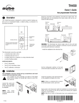
The thermostat normally displays the actual (ambient) temperature.
• To view the setpoint temperature, briefly press the Up or Down button. The setpoint will
be displayed for 5 seconds and the screen illuminated for 12 seconds.
• To change the setpoint temperature, press the Up or Down button until the desired
value is displayed.
Temperature display and setting
Temperature display
Heating intensity indicator.
(No image appears when
heating is off.)
Up button
Down button
Appears when the setpoint is displayed
Appears when the thermostat
is configured for 5-minute
cycles. The thermostat must be
set to this configuration if it is
controlling a fan-forced heater.
400-401-001-A (TH401) 5 x 3.5 EFS.book Page 2 Tuesday, November 17, 2009 9:21 AM

Owner’s Guide
3
ENGLISH
TURN OFF POWER OF THE HEATING SYSTEM AT THE MAIN POWER
PANEL TO AVOID ELECTRIC SHOCK.
Loosen the screw holding the faceplate to
the base. The screw cannot be completely
removed and remains captive on the base.
Remove the faceplate from the base by
pulling the bottom half.
Removing the faceplate
400-401-001-A (TH401) 5 x 3.5 EFS.book Page 3 Tuesday, November 17, 2009 9:21 AM

72838 / TH401
ENGLISH
4
Connect any one of
thermostat wires to the
heater (load) wire and the
other one to the power
supply wire using solderless
connectors for copper wires.
(The thermostat wires are
non-polarized; either wire
can be connected to the load
or to the power supply.)
NOTE: All cables and connections must conform to the local electrical code.
Special CO/ALR solderless connectors must be used when connecting with
aluminium conductors.
Wiring
2-wire installation
4-wire installation
400-401-001-A (TH401) 5 x 3.5 EFS.book Page 4 Tuesday, November 17, 2009 9:21 AM

Owner’s Guide
5
ENGLISH
Install the base onto an electrical
box.
Reinstall the faceplate on the base
and secure it in place with the
screw.
NOTE: Keep the air vents of ther-
mostat clean and unobstructed at
all times.
Installing the faceplate
400-401-001-A (TH401) 5 x 3.5 EFS.book Page 5 Tuesday, November 17, 2009 9:21 AM

72838 / TH401
ENGLISH
6
The setup menu is shown on the following page.
n Press the Up and Down buttons simultaneously for three seconds to enter
the setup menu.
o Press the Up or Down button to change the option.
p Press the Up and Down buttons simultaneously for one second to advance
to the next parameter.
q When the last parameter is displayed, press the Up and Down buttons for
three seconds to save any changes and exit the menu.
NOTE:
If you do not press any button for one minute,
the thermostat will automati-
cally save any changes you have made and will then
return to its normal display
.
Setup procedure
400-401-001-A (TH401) 5 x 3.5 EFS.book Page 6 Tuesday, November 17, 2009 9:21 AM

Owner’s Guide
7
ENGLISH
Setup menu
Parameter Options
Display and
default setting
Temperature display format
•°C
•°F
Heating cycle
• Std (conventional heating): 15 seconds
• Fan (fan-forced heating): 5 minutes
Minimum setpoint 5°C - 20°C (41°F - 68°F)
Maximum setpoint 15°C - 30°C (59°F - 86°F)
400-401-001-A (TH401) 5 x 3.5 EFS.book Page 7 Tuesday, November 17, 2009 9:21 AM

72838 / TH401
ENGLISH
8
In case of difficulty
PROBLEM SOLUTIONS
Thermostat is hot. This is normal.
Displayed tempera-
ture is wrong.
Remediate if any the following conditions exists:
• The thermostat is exposed to air draft.
• The sticker on the thermostat’s screen has not been removed.
• The thermostat is located near or above a heat source such as
a light dimmer.
Display disappears
and reappears after
a few minutes.
The thermal protection device on the heater has temporarily
opened. This can happen if the heater is obstructed by furniture or
curtain and has overheated, or if the heater’s thermal protection
device is too sensitive.
400-401-001-A (TH401) 5 x 3.5 EFS.book Page 8 Tuesday, November 17, 2009 9:21 AM

Owner’s Guide
9
ENGLISH
- Supply: 120/240 VAC, 60 Hz
- Minimum load: 0.83 A (resistive only)
200 W @ 240 VAC
100 W @ 120 VAC
- Maximum load: 10.4 A (resistive only)
2500 W @ 240 VAC
1250 W @ 120 VAC
- Display range: 0°C to 50°C (32°F to 122°F)
- Setpoint range: 5°C to 30°C (40°F to 85°F)
- Storage: -20°C to 50°C (-4°F to 120°F)
- Heating cycle length: 15 seconds / 5 minutes (user-selectable)
- Permanent memory: You do not need to adjust the temperature following a power outage.
Specifications
400-401-001-A (TH401) 5 x 3.5 EFS.book Page 9 Tuesday, November 17, 2009 9:21 AM

72838 / TH401
ENGLISH
10
Honeywell warrants this product, excluding battery, to be free from defects in the
workmanship or materials, under normal use and service, for a period of one (1) year from
the date of purchase by the consumer. If at any time during the warranty period the product
is determined to be defective or malfunctions, Honeywell shall repair or replace it (at
Honeywell's option).
If the product is defective,
(i) return it, with a bill of sale or other dated proof of purchase, to the place from which you
purchased it, or
(ii) call Honeywell Customer Care at 1-800-468-1502. Customer Care will make the
determination whether the product should be returned to the following address:
Honeywell Return Goods, Dock 4 MN10-3860, 1885 Douglas Dr N, Golden Valley, MN
55422, or whether a replacement product can be sent to you.
This warranty does not cover removal or reinstallation costs. This warranty shall not apply if
it is shown by Honeywell that the defect or malfunction was caused by damage which
occurred while the product was in the possession of a consumer.
Warranty
400-401-001-A (TH401) 5 x 3.5 EFS.book Page 10 Tuesday, November 17, 2009 9:21 AM

Owner’s Guide
11
ENGLISH
Honeywell's sole responsibility shall be to repair or replace the product within the terms
stated above. HONEYWELL SHALL NOT BE LIABLE FOR ANY LOSS OR DAMAGE OF
ANY KIND, INCLUDING ANY INCIDENTAL OR CONSEQUENTIAL DAMAGES
RESULTING, DIRECTLY OR INDIRECTLY, FROM ANY BREACH OF ANY WARRANTY,
EXPRESS OR IMPLIED, OR ANY OTHER FAILURE OF THIS PRODUCT. Some states do
not allow the exclusion or limitation of incidental or consequential damages, so this limitation
may not apply to you.
THIS WARRANTY IS THE ONLY EXPRESS WARRANTY HONEYWELL MAKES ON THIS
PRODUCT. THE DURATION OF ANY IMPLIED WARRANTIES, INCLUDING THE
WARRANTIES OF MERCHANTABILITY AND FITNESS FOR A PARTICULAR PURPOSE,
IS HEREBY LIMITED TO THE ONE-YEAR DURATION OF THIS WARRANTY. Some states
do not allow limitations on how long an implied warranty lasts, so the above limitation may
not apply to you.
This warranty gives you specific legal rights, and you may have other rights which vary from
state to state.
If you have any questions concerning this warranty, please write Honeywell Customer
Relations, 1985 Douglas Dr, Golden Valley, MN 55422 or call 1-800-468-1502. In Canada,
write Retail Products ON15-02H, Honeywell Limited/Honeywell Limitée, 35 Dynamic Drive,
Scarborough, Ontario M1V 4Z9.
400-401-001-A (TH401) 5 x 3.5 EFS.book Page 11 Tuesday, November 17, 2009 9:21 AM

400-401-001-A (TH401) 5 x 3.5 EFS.book Page 0 Tuesday, November 17, 2009 9:21 AM

400-401-001-A 2009-11-17
400-401-001-A (TH401) 5 x 3.5 EFS.book Page 1 Tuesday, November 17, 2009 9:21 AM
/