2
DDX418/DDX4048BT/DDX318/DDX3048
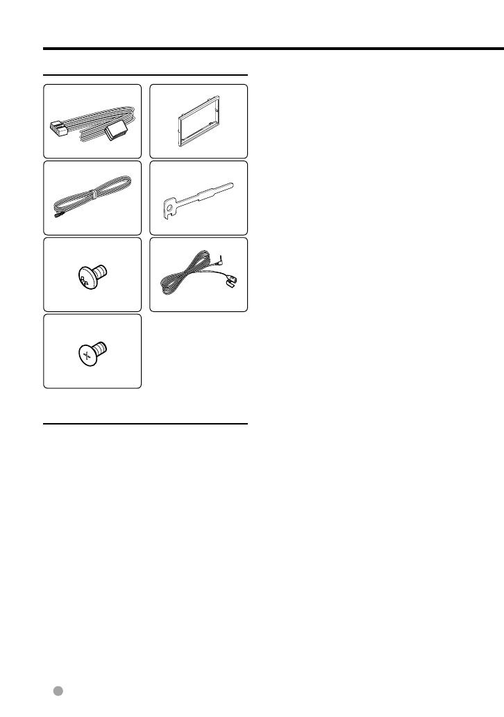
Accessories
1
..........1
2
..........1 (2m: 6.5 ft)
3
..........6
4
..........6
5
..........1
6
..........2
7*
1
..........1 (3m: 9.8 ft)
*
1
DDX418/ DDX4048BT
only.
Installation Procedure
1 To prevent a short circuit, remove the key
from the ignition and disconnect the -
battery.
2 Make the proper input and output wire
connections for each unit.
3 Connect the speaker wires of the wiring
harness.
4 Connect the wiring harness wires in the
following order: ground, battery, ignition.
5 Connect the wiring harness connector to
the unit.
6 Install the unit in your car.
7 Reconnect the - battery.
8 Press the reset button.
9 Perform the Initial Setup. (Refer to the
Instruction Manual.)
2WARNING
• If you connect the ignition wire (red) and the
battery wire (yellow) to the car chassis (ground),
you may cause a short circuit, that in turn may
start a fire. Always connect those wires to the
power source running through the fuse box.
• Do not cut out the fuse from the ignition wire
(red) and the battery wire (yellow). The power
supply must be connected to the wires via the
fuse.
After the Installation
After the installation, perform the Initial Setup
by referring to the instruction manual.
¤
• Mounting and wiring this product requires
skills and experience. For best safety, leave the
mounting and wiring work to professionals.
• Make sure to ground the unit to a negative 12V
DC power supply.
• Do not install the unit in a spot exposed to direct
sunlight or excessive heat or humidity. Also avoid
places with too much dust or the possibility of
water splashing.
• Do not use your own screws. Use only the screws
provided. If you use the wrong screws, you could
damage the unit.
• If the power is not turned ON ("Miswiring
DC Offset Error", "Warning DC Offset Error" is
displayed), the speaker wire may have a short-
circuit or touched the chassis of the vehicle and
the protection function may have been activated.
Therefore, the speaker wire should be checked.
• If your car’s ignition does not have an ACC
position, connect the ignition wires to a power
source that can be turned on and off with the
ignition key. If you connect the ignition wire to
a power source with a constant voltage supply,
such as with battery wires, the battery may be
drained.
• If the console has a lid, make sure to install the
unit so that the faceplate will not hit the lid when
closing and opening.
• If the fuse blows, first make sure the wires aren’t
touching to cause a short circuit, then replace the
old fuse with one with the same rating.
Accessories/ Installation Procedure


