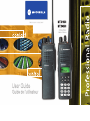
Motorola MTX4550 User manual
- Category
- Two-way radios
- Type
- User manual
This manual is also suitable for
Page is loading ...
Page is loading ...

1
English
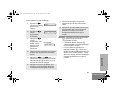
CONTENTS
COMPUTER SOFTWARE
COPYRIGHTS . . . . . . . . . . . . . . . . . . . . . . 4
Safety . . . . . . . . . . . . . . . . . . . . . . . . . . . . 5
Radio Overview . . . . . . . . . . . . . . . . . . . . 6
Parts of the Radio . . . . . . . . . . . . . . . . . . . 6
MTX1550 and MTX4550 Models . . . . . 6
On/Off/Volume Knob. . . . . . . . . . . . . . . 7
Mode Selector Knob . . . . . . . . . . . . . . . 7
Push-to-Talk (PTT) Button . . . . . . . . . . 7
LED Indicator . . . . . . . . . . . . . . . . . . . . 7
Microphone . . . . . . . . . . . . . . . . . . . . . . 7
Programmable Buttons . . . . . . . . . . . . . 7
Keypad Keys (For Model II Radios
Only) . . . . . . . . . . . . . . . . . . . . . . . . . . . 9
Menu Keys (For Model II Radios
Only) . . . . . . . . . . . . . . . . . . . . . . . . . . 10
Selecting a Feature. . . . . . . . . . . . . . . 10
Menu Display . . . . . . . . . . . . . . . . . . . 11
LCD Screen and Icons . . . . . . . . . . . . 11
Alert Tone Indications . . . . . . . . . . . . . 12
Getting Started . . . . . . . . . . . . . . . . . . . . 14
Battery Information. . . . . . . . . . . . . . . . . . 14
Battery Care and Tips . . . . . . . . . . . . .14
Recycling or Disposal of Batteries . . . .15
Charging the Battery . . . . . . . . . . . . . .15
Accessory Information . . . . . . . . . . . . . . . .16
Attaching the Battery . . . . . . . . . . . . . .16
Removing the Battery. . . . . . . . . . . . . .16
Attaching the Antenna . . . . . . . . . . . . .17
Removing the Antenna. . . . . . . . . . . . .17
Attaching the Belt Clip . . . . . . . . . . . . .18
Removing the Belt Clip. . . . . . . . . . . . .18
Radio Operation . . . . . . . . . . . . . . . . . . . .19
Turning the Radio On or Off . . . . . . . . .19
Adjusting the Radio’s Volume . . . . . . .19
Radio Self Test. . . . . . . . . . . . . . . . . . .19
Basic Radio Calls . . . . . . . . . . . . . . . . . .20
Selecting a Zone and Mode. . . . . . . . . . . .20
Selecting a Zone (For Model II
Radios Only). . . . . . . . . . . . . . . . . . . . .20
Selecting a Mode . . . . . . . . . . . . . . . . .20
Receiving a Call. . . . . . . . . . . . . . . . . . . . .21
Making a Call. . . . . . . . . . . . . . . . . . . . . . .21
Conventional Modes. . . . . . . . . . . . . . .21
Trunked Modes . . . . . . . . . . . . . . . . . .21
Low-Battery Alert . . . . . . . . . . . . . . . . .22
Coded Squelch Operation . . . . . . . . . .22
CONTENTS
20L01-A_PR_UG_MTX4500.book Page 1 Friday, April 13, 2007 2:47 PM

2
English
CONTENTS
Variable RF Power Level (Selected
Models Only) . . . . . . . . . . . . . . . . . . . . 22
Failsoft Operation (Trunked Systems
Only) . . . . . . . . . . . . . . . . . . . . . . . . . . . . . 22
Muting the Keypad Tones (For Keypad
Radios Only). . . . . . . . . . . . . . . . . . . . . . . 23
Trunked Features . . . . . . . . . . . . . . . . . . 24
Viewing Your Radio’s ID Number . . . . . . . 24
Enhanced Private Call Operation . . . . . . . 24
Answering a Private Call . . . . . . . . . . . 24
Making a Private Call. . . . . . . . . . . . . . 25
Leaving a Call Alert Page . . . . . . . . . . 28
Call Alert Operation . . . . . . . . . . . . . . . . . 29
Answering a Call Alert Page with a
Group Call . . . . . . . . . . . . . . . . . . . . . . 29
Making a Call Alert . . . . . . . . . . . . . . . 29
Automatic Multiple Site Selection
(AMSS) . . . . . . . . . . . . . . . . . . . . . . . . . . . 32
Viewing the Current Site . . . . . . . . . . . 32
Forcing a Site Change. . . . . . . . . . . . . 32
Locking and Unlocking a Site . . . . . . . 32
Conventional Features. . . . . . . . . . . . . . 33
Repeat/Direct . . . . . . . . . . . . . . . . . . . . . . 33
Smart PTT . . . . . . . . . . . . . . . . . . . . . . . . 34
Scan. . . . . . . . . . . . . . . . . . . . . . . . . . . . . 35
Scan Operation . . . . . . . . . . . . . . . . . . . . 35
Turning Scan On or Off with the
Keypad (For Keypad Radios Only) . . . 35
Deleting Nuisance Modes . . . . . . . . . . 36
Viewing a Scan List (For Keypad
Radios Only) . . . . . . . . . . . . . . . . . . . . 36
Programming a Scan List (For
Keypad Radios Only) . . . . . . . . . . . . . 37
Scan Modes . . . . . . . . . . . . . . . . . . . . 38
Programming the Radio . . . . . . . . . . . . 39
Programming the Telephone List
Numbers . . . . . . . . . . . . . . . . . . . . . . . 39
Programming the Call List. . . . . . . . . . 40
Telephone Operation . . . . . . . . . . . . . . . 42
Answering a Telephone Call . . . . . . . . 42
Making a Telephone Call (For
Model II Radios Only) . . . . . . . . . . . . . 42
Special Features. . . . . . . . . . . . . . . . . . . 46
Emergency Operation . . . . . . . . . . . . . . . 46
Sending an Emergency Alarm . . . . . . 46
Sending a Silent Emergency Alarm . . 47
20L01-A_PR_UG_MTX4500.book Page 2 Friday, April 13, 2007 2:47 PM

3
English
CONTENTS
Canceling an Emergency Alarm . . . . . 47
Sending an Emergency Call . . . . . . . . 47
Ending an Emergency Call . . . . . . . . . 48
Emergency with Voice to Follow . . . . . 48
Dynamic Regrouping. . . . . . . . . . . . . . . . . 48
Mode Selection . . . . . . . . . . . . . . . . . . 48
Select Enable and Disable. . . . . . . . . . 49
SmartZone Operation . . . . . . . . . . . . . . . 50
Benefits of SmartZone . . . . . . . . . . . . . . . 50
Site Switching in SmartZone . . . . . . . . 51
Viewing the Current Site . . . . . . . . . . . 52
Forcing a Site Change . . . . . . . . . . . . . 52
Locking and Unlocking a Site. . . . . . . . 52
Preferred Site Selection . . . . . . . . . . . . 53
Busy Override . . . . . . . . . . . . . . . . . . . 53
Site Trunking . . . . . . . . . . . . . . . . . . . . 54
Stat-Alert Features . . . . . . . . . . . . . . . . . 55
Viewing Your Radio’s ID Number . . . . . . . 55
Stat-Alert Voice Selective Call
Operation . . . . . . . . . . . . . . . . . . . . . . . . . 55
Receiving a Voice Selective Call . . . . . 56
Making a Voice Selective Call . . . . . . . 56
Stat-Alert Call Alert Operation. . . . . . . . . . 58
Receiving a Call Alert Page . . . . . . . . . 58
Making a Call Alert. . . . . . . . . . . . . . . . 59
PTT-ID . . . . . . . . . . . . . . . . . . . . . . . . . . . 60
Radio Check. . . . . . . . . . . . . . . . . . . . . . . 60
Emergency Operation. . . . . . . . . . . . . . . . 60
Accessories . . . . . . . . . . . . . . . . . . . . . . 61
Adapters . . . . . . . . . . . . . . . . . . . . . . . . . . 61
Antennas . . . . . . . . . . . . . . . . . . . . . . . . . 61
Batteries . . . . . . . . . . . . . . . . . . . . . . . . . . 61
Belt . . . . . . . . . . . . . . . . . . . . . . . . . . . . . . 61
Carry Cases . . . . . . . . . . . . . . . . . . . . . . . 61
Chargers. . . . . . . . . . . . . . . . . . . . . . . . . . 61
Covers . . . . . . . . . . . . . . . . . . . . . . . . . . . 61
Headsets . . . . . . . . . . . . . . . . . . . . . . . . . 62
Remote Speaker Microphones. . . . . . . . . 62
Warranty . . . . . . . . . . . . . . . . . . . . . . . . . 63
Limited Warranty . . . . . . . . . . . . . . . . . . 63
20L01-A_PR_UG_MTX4500.book Page 3 Friday, April 13, 2007 2:47 PM

COMPUTER SOFTWARE
COPYRIGHTS
4
English
COMPUTER SOFTWARE
COPYRIGHTS
The Motorola products described in this
manual may include copyrighted Motorola
computer programs stored in semiconductor
memories or other media. Laws in the United
States and other countries preserve for
Motorola certain exclusive rights for
copyrighted computer programs, including, but
not limited to, the exclusive right to copy or
reproduce in any form the copyrighted
computer program.
Accordingly, any copyrighted Motorola
computer programs contained in the Motorola
products described in this manual may not be
copied, reproduced, modified, reverse-
engineered, or distributed in any manner
without the express written permission of
Motorola. Furthermore, the purchase of
Motorola products shall not be deemed to
grant either directly or by implication, estoppel,
or otherwise, any license under the copyrights,
patents or patent applications of Motorola,
except for the normal non-exclusive license to
use that arises by operation of law in the sale
of a product.
20L01-A_PR_UG_MTX4500.book Page 4 Friday, April 13, 2007 2:47 PM

5
English
SAFETY
SAFETY
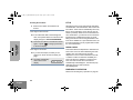
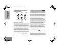
This user guide covers the operation of the
MTX1550 and MTX4550 Portable Radios.
This radio is restricted to occupational use only to
satisfy ICNIRP RF energy exposure requirements.
Before using this product, read the RF energy
awareness information and operating instructions in
the Product Safety and RF Exposure booklet
(Motorola Publication part number 6881095C98_) to
ensure compliance with RF energy exposure limits.
Before using this product, read the operating
instructions for safe usage contained in the
Product Safety and RF Exposure booklet
6881095C98_ enclosed with your radio.
!
20L01-A_PR_UG_MTX4500.book Page 5 Friday, April 13, 2007 2:47 PM

English
RADIO OVERVIEW
6
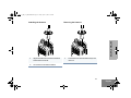
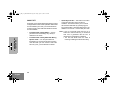
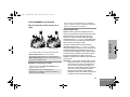
RADIO OVERVIEW
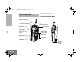
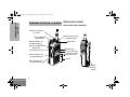
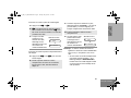
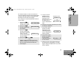
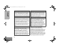
PARTS OF THE RADIO
MTX1550 and MTX4550 Models
(Programmable)/
Side Button 1 (A)
(Programmable)
Side Button 3 (C)
(Programmable)
Top Button (D)
Keypad
Menu Keys
Mode Selector Knob
Button
Push-to-Talk (PTT)
On/Off/Volume Knob
LED Indicator
(Programmable)
Side Button 2 (B)
LCD Screen
Microphone
Select Button
Side
Connector
Cover
Side
Connector
Cover
20L01-A_PR_UG_MTX4500.book Page 6 Friday, April 13, 2007 2:47 PM

7
English
RADIO OVERVIEW
On/Off/Volume Knob
Turns the radio on or off, and adjusts the radio’s
volume.
Mode Selector Knob
Selects the required operation mode.
Push-to-Talk (PTT) Button
Press and hold down this button to talk; release to
listen.
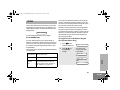
LED Indicator
Indicates status of radio operating conditions (see
table below):
Microphone
When sending a message, hold the microphone 1 to
2 inches (2.5 to 5 cm) away from your mouth, and
speak clearly into the microphone.
Programmable Buttons
Several of your radio buttons can be programmed (by
using the Customer Programming Software — CPS)
to activate the radio features.
Programmable buttons are:
• Top button
• Three side buttons
Check with your dealer or Motorola representative for
a complete list of the functions your radio’s
programmable buttons support.
With PTT Switch Pressed (Radio Transmitting)
Steady red
Radio is transmitting (PTT button
pressed)
LED unlit Radio is not transmitting
Blinking red
Low battery (conventional mode
only; programmable by
authorized Motorola dealer).
Momentary
green
Radio has powered-up
successfully
With PTT Released (Radio Receiving)
Blinking red
Mode busy (conventional
mode only)
Blinking green
Receipt of a telephone call,
Private Conversation call, or
Call Alert page
20L01-A_PR_UG_MTX4500.book Page 7 Friday, April 13, 2007 2:47 PM

8
English
RADIO OVERVIEW
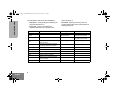
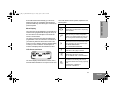
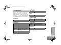
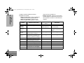
The table below shows the functions available by:
• short press - quickly pressing and releasing the
programmable buttons, or
• long press - pressing and holding the
programmable buttons for a period of time
before releasing, or
• hold down- pressing and holding down the
programmable buttons while checking status or
making adjustments.
Button Short Press Long Press Hold Down
Monitor/Permanent
Monitor
—
Continually monitors the
selected channel.
Monitors the selected
channel for any activity.
Volume Set — —
Sounds a tone for adjusting
the radio’s volume level.
Scan
Toggles between the start/stop of the
Scan operation.
— —
Nuisance Delete
Temporarily deletes an unwanted
non-priority active scan member.
— —
Search Makes a system search.
Light Turns on/off your radio’s backlight. — —
Emergency Enters Emergency mode. Leaves Emergency mode. —
Call Enters or exits a Private call.
Page Enters or exits a Call Alert.
Call Response
Respond to or exit from a Private
Call or Call Alert.
— —
Phone Enters or leaves Phone mode. — —
20L01-A_PR_UG_MTX4500.book Page 8 Friday, April 13, 2007 2:47 PM

9
English
RADIO OVERVIEW
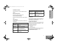
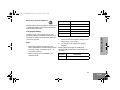
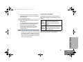
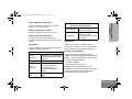
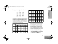
Keypad Keys (For Model II Radios Only)
These keys are used when dialing a phone number,
making a radio call or entering information for
programming the radio’s lists.
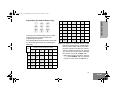
The following table shows the character cycle for each
key, when entering information for programming the
radio’s lists.
Note: The sequence in the table above is valid
when entering information on a blank display.
However, when editing existing information,
the above sequence may differ. For instance,
if the last character entered is a “R”, pressing
7 to enter the next character, would start
the character cycle at “S” and NOT at “P”.
• When editing existing information, pressing
1 would ALWAYS start the character
cycle at the “blank space” and NOT at “1”.
Key
Number of Times the Key is Pressed
1 2 3 4 5 6
0 0
1 1
Blank
space
2 A B C 2
3 D E F 3
4 G H I 4
123
456
789
*0#
5 J K L 5
6 M N O 6
7 P Q R S 7
8 T U V 8
9 W X Y Z 9
*
*
# # - + . / \
20L01-A_PR_UG_MTX4500.book Page 9 Friday, April 13, 2007 2:47 PM

10
English
RADIO OVERVIEW
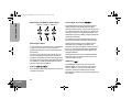
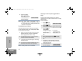
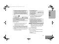
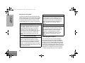
Menu Keys (For Model II Radios Only)
Selecting a Feature
A unique feature of your radio is its use of the display
to give you quick access to many of the radio’s
features without having to have a dedicated key for
each feature.
The names of the features (CALL, MUTE, etc.) are
shown on the display, three at a time. Selection of
features is controlled by the three keys directly below
the feature names: the left key controls the left feature,
the middle key controls the middle feature, and the
right key controls the right feature.
Softkeys (l;l)
When already in Menu Mode, these keys are used to
make Menu selections.
Left and Right Arrow Keys (,/)
The left and right arrow keys are used to scroll the
display forward or backward through the radio’s
features and lists. There is no end point to the list, so if
you continue to scroll in one direction, the display will
“wrap around” back to the beginning of the list. If you
hold either key down, the display scrolls at a faster rate
until the key is released.
The left arrow key is also used for editing when you
are entering information manually from the keypad.
Pressing the left arrow key, when editing numeric
information (such as telephone numbers), will
backspace, and erase the display, one character at a
time. If you have erased all the digits, an additional
press of the left arrow key returns the display to the
preprogrammed list.
Pressing the left arrow key, when editing alphabetic
information (such as member’s names), moves the
cursor one step to the left.
HOME Key ( )
The HOME key always returns you to the home
(default) display. In most cases, this is the current
mode. In addition, if you are using a feature that
requires it, pressing the HOME key also causes
information to be saved in memory before going to the
home display.
l;l
,/
Softkey 1
Softkey 3
Left Home
Right
Softkey 2
20L01-A_PR_UG_MTX4500.book Page 10 Friday, April 13, 2007 2:47 PM

11
English
RADIO OVERVIEW
Some radio features automatically go to the home
display when they are completed, without having to
press the HOME key, thus reducing the number of key
presses required.
Menu Display
The menu items can be displayed in normal video or in
reversed video (programmable through the CPS). All
the menu items in the examples in this manual are
shown in reversed video.
The order in which the menu items are displayed is
programmable. Thus, the order of the menu items on
your radio may differ from those shown here in this
manual. In such a situation, press the relevant softkey
to make your menu selections. All descriptions of
functions and displays after the selection are valid.
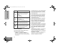
LCD Screen and Icons
The screen displays mode selected, channel, menu,
and radio status information. The top two screen rows
show radio status indicator symbols, explained in the
following table.
Symbol Name and Description
A
XPAND™ Indicator
Indicates that your radio has the companding
feature activated.
B
Power Level Indicator
R lights up when your radio is configured to
transmit in Low Power. S lights up when your
radio is configured to transmit in High Power.
C
Carrier Squelch Indicator
Indicates when the active conventional mode is
being monitored in the carrier squelch mode;
ON = BEING MONITORED/
OFF = NOT BEING MONITORED.
F
Call Received
Blinks when a call or page is received.
G
Scan Indicator
Indicates when the radio is scanning;
ON = SCANNING / OFF = NOT SCANNING.
H
Priority Scan
The presence of a dot along with the scan
annunciator indicates the receiving of a priority
mode;
BLINKING DOT = PRIORITY 1
SOLID DOT = PRIORITY 2.
20L01-A_PR_UG_MTX4500.book Page 11 Friday, April 13, 2007 2:47 PM

12
English
RADIO OVERVIEW
Alert Tone Indications
Your radio generates a number of audible tones to
indicate radio operating conditions:
• Low Battery – A low-battery condition is
indicated by a high-pitched, cricket-like “chirp-
chirp” when the PTT switch is released following
a transmission.
• Successful Power-Up – A short, medium-pitched
tone when the radio is first turned on indicates
that the radio has passed its power-up self test
and is ready for use.
• Unsuccessful Power-Up – A short, low-pitched
tone when the radio is first turned on indicates
that the radio has failed its power-up self test
and is not ready for use. Contact your service
representative for service.
• Transmit on Receive-Only Mode – If you press
the PTT switch while tuned to a “receive-only”
mode, you will hear a continuous, low-pitched
alert tone, indicating that no transmission is
possible on this mode. This tone will continue
until the PTT switch is released.
• Transmit Inhibit on Busy Mode – If you press the
PTT switch while the mode is busy, you will hear
a continuous, low-pitched alert tone, indicating
that no transmission is possible on this mode.
This tone will continue until the PTT switch is
released.
• Transmit Inhibit on Flat Battery – If you press the
PTT while the battery is flat, you will hear a
continuous, low pitched alert tone, indicating that
transmission is impossible.
• Invalid Mode – A continuous, low-pitched tone is
heard when an invalid or unprogrammed
operation is attempted on the radio.
J
Direct
Indicates whether you are talking directly to
another radio (talkaround), or through a
repeater;
ON = DIRECT
OFF = REPEATER.
K
Programming/Viewing Mode
Indicates when the radio is in the programming
or viewing mode;
ON = IN VIEWING MODE
BLINKING = IN PROGRAMMING MODE.
M
Signal Quality Indicator
Shows the radio signal quality. Five bars
indicates the best signal (Smart Zone Only).
P
Battery Level Indicator
Shows the remaining charge in your battery,
based on how many bars are displayed.
Blinking, indicates flat battery.
Symbol Name and Description
20L01-A_PR_UG_MTX4500.book Page 12 Friday, April 13, 2007 2:47 PM

13
English
RADIO OVERVIEW
• Valid (Good) Key Press – A short, medium-
pitched tone when a keypad key is pressed
indicates that the key press was accepted.
• Invalid (Bad) Key Press – A short, low-pitched
tone when a keypad key is pressed indicates
that the key press was rejected.
• Emergency Alarm Entry – A short, medium-
pitched tone when the emergency button is
pressed indicates that the radio has entered the
emergency mode.
• Emergency Alarm/Call Exit – A continuous,
medium-pitched tone when the radio is in the
emergency mode indicates that the radio has
exited the emergency mode.
• Failsoft (Trunked Systems Only) – A faint
“beeping” tone every ten seconds indicates that
the radio is operating in the failsoft mode.
• Time-Out Timer Warning – Your radio’s time-out
timer limits the length of your transmission time.
When you are pressing the PTT switch
(transmitting), a short, low-pitched warning tone
will sound four seconds before the allotted time
expires.
• Time-Out Timer Timed-Out – If you hold down
the PTT switch longer than the time-out timer’s
allotted time, a continuous, low-pitched tone
sounds, indicating that your transmission has
been cut off. This tone will continue until the PTT
switch is released.
• Phone Busy – A “bah-bah-bah-bah” tone when
telephone interconnect is accessed indicates
that all available modes are busy and the radio is
in queue for the next available phone line.
• Call Alert™ (Page) Received – A group of four
medium-pitched tones every five seconds
indicates that your radio has received a Call
Alert page.
• Call Alert™ (Page) Sent – A single medium-
pitched tone (central acknowledge), followed by
a group of four medium-pitched tones indicates
that a Call Alert page sent by your radio has
been received by the target radio.
• Private Conversation™ Call Received – A group
of two medium-pitched tones indicates that your
radio has received a Private Conversation call.
This sequence is repeated every five seconds
for approximately 20 seconds for enhanced
Private Conversation.
• Trunked System Busy (Trunked Systems Only) –
A “bah-bah-bah-bah” tone when a trunked
system is accessed indicates that all available
channels are busy and the radio is in queue for
the next available channel.
• Call Back (Trunked Systems Only) – A group of
three medium-pitched tones (di-di-dit) indicates
that a talkgroup is now available for your
previously requested transmission.
20L01-A_PR_UG_MTX4500.book Page 13 Friday, April 13, 2007 2:47 PM

14
English
GETTING STARTED
GETTING STARTED
BATTERY INFORMATION
Battery Care and Tips
This product is powered by a lithium-ion rechargeable
battery.
The following battery tips will help you obtain the
highest performance and longest cycle life from your
Motorola rechargeable battery.
• Charge your new battery overnight (14 – 16
hours) before using it to obtain maximum
battery capacity and performance.
• Charging in non-Motorola equipment may lead
to battery damage and void the battery warranty.
• When charging a battery that is attached to the
radio, turn the radio off to ensure a full charge.
• The battery should be at about 25°C (room
temperature) whenever possible. Charging a
cold battery (below 10°C) may result in leakage
of electrolyte and ultimately, in failure of the
battery.
• Charging a hot battery (above 35°C) results in
reduced discharge capacity, affecting the
performance of the radio. Motorola rapid-rate
battery chargers contain a temperature-sensing
circuit to ensure that the battery is charged
within these temperature limits.
• New batteries can be stored up to two years
without significant cycle loss. Store new/unused
batteries in a cool dry area.
• Batteries which have been in storage should be
charged overnight.
• Do not return fully charged batteries to the
charger for an “extra boost”. This action
significantly reduces cycle life.
• Do not leave your radio and battery in the
charger when not charging. Continuous charging
shortens battery life. (Do not use your charger
as a radio stand.)
• For optimum battery life and operation use only
Motorola brand chargers. They were designed to
operate as an integrated energy system.
20L01-A_PR_UG_MTX4500.book Page 14 Friday, April 13, 2007 2:47 PM

15
English
GETTING STARTED
Recycling or Disposal of Batteries
Motorola endorses and encourages the recycling of all
re-chargeable batteries. Contact your local Motorola
dealer for further information.
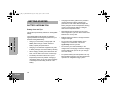
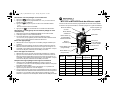
Charging the Battery
If a battery is new, or its charge level is very low,
indicated by battery level indicator showing one or no
segments, you need to charge the battery before you
can use it in your radio.
Note:
• Batteries are shipped uncharged from the
factory. New batteries could prematurely indicate
full charge, charge a new battery for 14 – 16
hours before initial use.
• Battery charging must occur ONLY in non-
hazardous areas.
1. Place the radio with the battery attached, or the
battery alone, in the charger.
2. The charger’s LED indicates the charging
progress.
Battery chargers will charge only the Motorola
authorized batteries listed below; other batteries will
not charge.
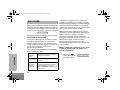
NiCd
Charger LED Status
Red Battery is charging
Green Battery is fully charged
Blinking Red* Battery is unchargeable
Blinking Yellow Charger is getting ready to charge
Blinking Green Battery is 90% charged
*
Battery is damaged. Please contact your dealer.
Part No. Description
NNTN5510 Li-Ion Battery 1480mAH (FM_C)
20L01-A_PR_UG_MTX4500.book Page 15 Friday, April 13, 2007 2:47 PM

16
English
GETTING STARTED
ACCESSORY INFORMATION
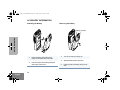
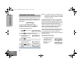
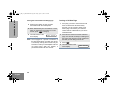
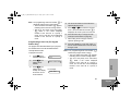
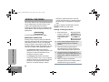
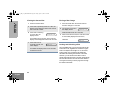
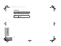
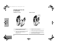
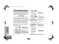
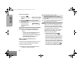
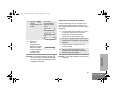
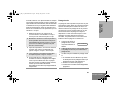
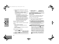
Attaching the Battery
Removing the Battery
1 Fit the extensions at the bottom of the
battery into the bottom slots of the radio.
2 Press the top part of the battery towards the
radio until you hear a click.
1 Turn off the radio (see page 19).
2 Slide both battery latches downward.
3 Pull the top part of the battery away from the
radio.
Battery Latches
20L01-A_PR_UG_MTX4500.book Page 16 Friday, April 13, 2007 2:47 PM

17
English
GETTING STARTED
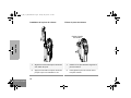
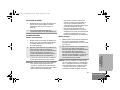
Attaching the Antenna Removing the Antenna
1 Align the threaded end of the antenna with the
radio’s antenna connector.
2 Turn the antenna clockwise to fasten it.
1 Turn the antenna counterclockwise until you can
remove it.
20L01-A_PR_UG_MTX4500.book Page 17 Friday, April 13, 2007 2:47 PM

18
English
GETTING STARTED
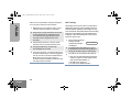
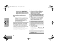
Attaching the Belt Clip Removing the Belt Clip
1 Align the grooves of the belt clip with those
of the battery.
2 Press the belt clip downward until you hear
a click.
1 Use a key to press the belt clip tab away
from the battery.
2 Slide the belt clip upward to remove it.
Belt Clip Tab
20L01-A_PR_UG_MTX4500.book Page 18 Friday, April 13, 2007 2:47 PM

19
English
GETTING STARTED
RADIO OPERATION
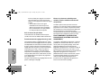
Turning the Radio On or Off
Adjusting the Radio’s Volume
Radio Self Test
Turn the radio on by rotating the volume control
clockwise. The radio goes through a power-up self
check and, if it passes the check, the display
momentarily shows SELF TEST. A good-power-up,
high-pitched tone sounds to indicate that the radio has
passed the self check.
If the radio fails the self check, the display shows
ERROR XX/XX (where XX/XX is an alphanumeric error
code), accompanied by a bad-power-up, low-pitched
tone. Turn the radio off, check the battery, and turn the
radio back on. If the radio still does not pass the self
check, a problem exists in the radio. Contact your
nearest Motorola Service Shop.
Note: The power-up self check verifies that the
radio’s microprocessor-based systems are
working, but it does not check all of the rf
components, nor does it check the operation
of all customer-specific features. Motorola
recommends that the functionality of the
radio be periodically checked by an
authorized Motorola service shop.
To turn the radio on, turn the On-Off/Volume Control
knob clockwise.
To turn the radio off, turn the On-Off/Volume Control
knob counterclockwise until you hear a click.
Turn the On-Off/Volume Control knob to adjust the
volume level.
Listen until you hear a transmission, then adjust the
volume control for a comfortable listening level.
Or, if a button is programmed for “volume set,” press this
button and adjust the volume to a comfortable listening
level.
ON OFF
20L01-A_PR_UG_MTX4500.book Page 19 Friday, April 13, 2007 2:47 PM

20
English
BASIC RADIO CALLS
BASIC RADIO CALLS
This section outlines the basic functions of your radio.
All references to what is shown on the display is only
valid for Model II radios. Throughout this section, the
display below
is used to indicate the radio’s home display.
SELECTING A ZONE AND MODE
A mode is a channel or talkgroup and all the features
that are programmed to it. A zone is a grouping of
modes that is selected using the menu keys. Before
you use your radio to receive or send messages, you
should first select the desired zone and mode.
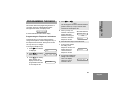
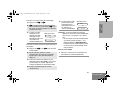
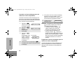
Selecting a Zone (For Model II Radios Only)
Selecting a Mode
1 Press / until
ZONE is displayed.
2 Press l (the
softkey below
ZONE). The current
zone name blinks on
the display.
For example
PLANT POLICE
ZONE
MUTE
CALL
PLANT POLICE
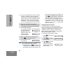
3 Press / until the
desired zone name is
displayed.
—or—
Enter the number of
the desired zone.
For example
4 Press .
5 The displayed zone is
the new selected
zone.
1 Turn the mode selector knob to the desired
mode.
2 The display shows
the selected mode’s
name.
For example
3 If the selected mode
is unprogrammed, an
invalid-mode tone is
heard until a valid
programmed mode is
selected.
CITY POLICE
CITY POLICE
PLANT MODE 1
UNPROGRAMMED
20L01-A_PR_UG_MTX4500.book Page 20 Friday, April 13, 2007 2:47 PM
Page is loading ...
Page is loading ...
Page is loading ...
Page is loading ...
Page is loading ...
Page is loading ...
Page is loading ...
Page is loading ...
Page is loading ...
Page is loading ...
Page is loading ...
Page is loading ...
Page is loading ...
Page is loading ...
Page is loading ...
Page is loading ...
Page is loading ...
Page is loading ...
Page is loading ...
Page is loading ...
Page is loading ...
Page is loading ...
Page is loading ...
Page is loading ...
Page is loading ...
Page is loading ...
Page is loading ...
Page is loading ...
Page is loading ...
Page is loading ...
Page is loading ...
Page is loading ...
Page is loading ...
Page is loading ...
Page is loading ...
Page is loading ...
Page is loading ...
Page is loading ...
Page is loading ...
Page is loading ...
Page is loading ...
Page is loading ...
Page is loading ...
Page is loading ...
Page is loading ...
Page is loading ...
Page is loading ...
Page is loading ...
Page is loading ...
Page is loading ...
Page is loading ...
Page is loading ...
Page is loading ...
Page is loading ...
Page is loading ...
Page is loading ...
Page is loading ...
Page is loading ...
Page is loading ...
Page is loading ...
Page is loading ...
Page is loading ...
Page is loading ...
Page is loading ...
Page is loading ...
Page is loading ...
Page is loading ...
Page is loading ...
Page is loading ...
Page is loading ...
Page is loading ...
Page is loading ...
Page is loading ...
Page is loading ...
Page is loading ...
Page is loading ...
Page is loading ...
Page is loading ...
Page is loading ...
Page is loading ...
Page is loading ...
Page is loading ...
Page is loading ...
Page is loading ...
Page is loading ...
Page is loading ...
Page is loading ...
Page is loading ...
Page is loading ...
Page is loading ...
Page is loading ...
Page is loading ...
Page is loading ...
Page is loading ...
Page is loading ...
Page is loading ...
Page is loading ...
Page is loading ...
Page is loading ...
Page is loading ...
Page is loading ...
Page is loading ...
Page is loading ...
Page is loading ...
Page is loading ...
Page is loading ...
Page is loading ...
Page is loading ...
Page is loading ...
Page is loading ...
Page is loading ...
Page is loading ...
Page is loading ...
Page is loading ...
Page is loading ...
Page is loading ...
Page is loading ...
Page is loading ...
Page is loading ...
Page is loading ...
Page is loading ...
Page is loading ...
Page is loading ...
Page is loading ...
-
 1
1
-
 2
2
-
 3
3
-
 4
4
-
 5
5
-
 6
6
-
 7
7
-
 8
8
-
 9
9
-
 10
10
-
 11
11
-
 12
12
-
 13
13
-
 14
14
-
 15
15
-
 16
16
-
 17
17
-
 18
18
-
 19
19
-
 20
20
-
 21
21
-
 22
22
-
 23
23
-
 24
24
-
 25
25
-
 26
26
-
 27
27
-
 28
28
-
 29
29
-
 30
30
-
 31
31
-
 32
32
-
 33
33
-
 34
34
-
 35
35
-
 36
36
-
 37
37
-
 38
38
-
 39
39
-
 40
40
-
 41
41
-
 42
42
-
 43
43
-
 44
44
-
 45
45
-
 46
46
-
 47
47
-
 48
48
-
 49
49
-
 50
50
-
 51
51
-
 52
52
-
 53
53
-
 54
54
-
 55
55
-
 56
56
-
 57
57
-
 58
58
-
 59
59
-
 60
60
-
 61
61
-
 62
62
-
 63
63
-
 64
64
-
 65
65
-
 66
66
-
 67
67
-
 68
68
-
 69
69
-
 70
70
-
 71
71
-
 72
72
-
 73
73
-
 74
74
-
 75
75
-
 76
76
-
 77
77
-
 78
78
-
 79
79
-
 80
80
-
 81
81
-
 82
82
-
 83
83
-
 84
84
-
 85
85
-
 86
86
-
 87
87
-
 88
88
-
 89
89
-
 90
90
-
 91
91
-
 92
92
-
 93
93
-
 94
94
-
 95
95
-
 96
96
-
 97
97
-
 98
98
-
 99
99
-
 100
100
-
 101
101
-
 102
102
-
 103
103
-
 104
104
-
 105
105
-
 106
106
-
 107
107
-
 108
108
-
 109
109
-
 110
110
-
 111
111
-
 112
112
-
 113
113
-
 114
114
-
 115
115
-
 116
116
-
 117
117
-
 118
118
-
 119
119
-
 120
120
-
 121
121
-
 122
122
-
 123
123
-
 124
124
-
 125
125
-
 126
126
-
 127
127
-
 128
128
-
 129
129
-
 130
130
-
 131
131
-
 132
132
-
 133
133
-
 134
134
-
 135
135
-
 136
136
-
 137
137
-
 138
138
-
 139
139
-
 140
140
-
 141
141
-
 142
142
-
 143
143
-
 144
144
-
 145
145
-
 146
146


Motorola MTX4550 User manual
- Category
- Two-way radios
- Type
- User manual
- This manual is also suitable for
Ask a question and I''ll find the answer in the document
Finding information in a document is now easier with AI
in other languages
- français: Motorola MTX4550 Manuel utilisateur
Related papers
-
Motorola MTX8250 LS User manual
-
-
-
-
-
-
-
-
-
Other documents
-
Nikon XTS-5000 User manual
-
Nikon 5000 User manual
-
Harris XG-15P series User manual
-
E.F. Johnson Company FM Portable Radio Intrinsically-Safe SMARTNET, SmartZone Conventional User manual
-
HP Compaq nw8440 Base Model Mobile Workstation Getting Started
-
-
Logicom FX 200 Owner's manual
-
Avaya EU DoC for 1100 Series Deskphones User manual
-
-
 quiko QK-TXTRC User manual
