
INSTALLATION, SERVICE AND MAINTENANCE INSTRUCTIONS
ANNEX FOR CE ATEX MARKED EQUIPMENT ACCORDING TO DIRECTIVE
2014/34/EU:
SIDE ENTRY AGITATOR
DINAMIX SMX Ex
Original Manual
20.073.30.05EN
(0) 2023/06
20.073.32.0010

(1) Where X is a numeric character
EU Declaration of Conformity
We,
INOXPA, S.A.U.
Telers, 60
17820 – Banyoles (Girona)
Hereby declare under our sole responsibility that the machine
BOTTOM SIDE ENTRY AGITATOR
Designation
DINAMIX SMX
From serial number IXXXXXXXXX to IXXXXXXXXX (1)
Is in compliance with applicable provisions of the following directive:
Directive ATEX 2014/34/EU
Applicable harmonized standards:
EN ISO 80079-36:2016
EN ISO 80079-37:2016
EN 1127-1:2019
EN 13237:2012
EN15198:2007
EN IEC 60079-0:2018
This Declaration of Conformity covers equipment with the following ATEX marking:
20.073.30.06EN
(0) 2023/07

(1) Where X is a numeric character
The technical documentation referenced 19733343-792634 is on file with the notified body
LABORATOIRE CENTRAL DES INDUSTRIES ELECTRIQUES (LCIE), 33, Av. du Général
Leclerc BP 8, 92266 Fontenay-aux-Roses, France. Reference num. 0081.
The person authorized to compile the technical documentation is the signer of this document.
Banyoles, 2023
David Reyero Brunet
Technical Office Manager

2 INOXPA S.A.U. 20.073.30.05EN · (0) 2023/06
1. Table of Contents
1. Table of Contents
2. Generalities
2.1. Instructions manual ....................................................................................................................................... 3
2.2. Compliance with the instructions .................................................................................................................. 3
2.3. Warranty ........................................................................................................................................................ 3
3. Safety
3.1. Warning symbols........................................................................................................................................... 4
3.2. General safety instructions ........................................................................................................................... 4
4. General Information
4.1. Description .................................................................................................................................................... 6
4.2. Principle of operation .................................................................................................................................... 6
4.3. Application ..................................................................................................................................................... 6
5. Installation
5.1. Reception of the agitator ............................................................................................................................... 8
5.2. Identification of the agitator ........................................................................................................................... 9
5.3. Transport and storage ................................................................................................................................... 9
5.4. Location ......................................................................................................................................................... 9
5.5. Electrical installation ................................................................................................................................... 10
5.6. Assembly ..................................................................................................................................................... 11
6. Start-up
7. Troubleshooting
8. Maintenance
8.1. General considerations ............................................................................................................................... 15
8.2. Maintenance ................................................................................................................................................ 15
8.3. Lubrication ................................................................................................................................................... 15
8.4. Spare parts .................................................................................................................................................. 15
8.5. Conservation ............................................................................................................................................... 16
8.6. Cleaning ...................................................................................................................................................... 16
8.7. Disassembly and assembly of the agitator ................................................................................................. 16
9. Technical Specifications
9.1. Materials ...................................................................................................................................................... 17
9.2. Other features ............................................................................................................................................. 17
9.3. Dimensions ................................................................................................................................................. 17
9.4. Parts list ...................................................................................................................................................... 17

Generalities
INOXPA S.A.U. 20.073.30.05EN · (0) 2023/06 3
2. Generalities
2.1. INSTRUCTIONS MANUAL
This manual contains information about the reception, installation, operation, assembly, disassembly and
maintenance of the DINAMIX SMX side entry agitator.
Carefully read the instruction prior to starting the agitator, familiarize yourself with the installation, operation and
correct use of the agitator and strictly follow the instructions. These instructions should be kept in a safe location
near the installation area.
The information published in the instruction manual is based on updated data.
INOXPA reserves the right to modify this instruction manual without prior notice.
2.2. COMPLIANCE WITH THE INSTRUCTIONS
Not following the instructions may impose a risk for the operators, the environment and the machine, and may
result in the loss of the right to claim damages.
This non-compliance may result in the following risks:
• failure of important machine/plant functions,
• failure of specific maintenance and repair procedures,
• possible electrical, mechanical and chemical hazards,
• risk to the environment due to the type of substances released.
2.3. WARRANTY
The conditions of the warranty are specified in the General Sales Condition that has been delivered at the time of
placing your order:
The machine may not undergo any modification without prior approval from the manufacturer.
For your safety, only use original spare parts and accessories. The usage of other parts will relieve
the manufacturer of any liability.
Changing the service conditions can only be carried out with prior written authorization from INOXPA.
The agitator was selected for use in explosive atmospheres at the time of placing the order, according to
ATEX form. INOXPA is not liable for any damage that may arise if the information provided by the buyer
is incomplete or incorrect (liquid type, viscosity, RPM, classification of the potentially explosive area, gas
generated by the potentially explosive atmosphere, etc).
Please do not hesitate to contact us in case of doubts or if further explanations are required regarding
specific data (adjustments, assembly, disassembly, etc.).

Safety
4 INOXPA S.A.U. 20.073.30.05EN · (0) 2023/06
3. Safety
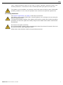
3.1. WARNING SYMBOLS
Safety hazard for people in general and/or for equipment
Electric hazard
Danger of formation of explosive atmospheres or generation of ignition sources of
potentially explosive atmospheres
Important instruction to prevent damage to the equipment and its functions
3.2. GENERAL SAFETY INSTRUCTIONS
Read the instruction manual carefully before installing and starting the agitator. Contact INOXPA in
case of doubt.
3.2.1. During the installation
The Technical Specifications of chapter 9 should always be observed.
The installation and use of the agitator should always be in accordance with applicable regulations
regarding health and safety.
Before starting up the agitator, check that it is properly anchored and its shaft is perfectly aligned.
Incorrect alignment and/or excessive stress during coupling can cause serious mechanical problems
in the agitator.
Take all possible precautions when lifting the agitator. Always use properly attached slings when
moving the agitator with a crane or other lifting device.
Keep the motor and the switchboard under control, particularly in areas where there is a risk of fire
or explosion.
When cleaning, do not spray directly on the engine.
Do not disassemble the agitator until the switchboard has been disconnected. Remove the fuses and
disconnect the power cable supplying the motor.
All electric work should be carried out by specialised personnel.
3.2.2. During operation
The Technical Specifications of chapter 9 should always be observed. Under no circumstances can
the specified limit values be exceeded.
Before starting up the agitator, remove all the tools used during the assembly.
Do not operate the agitator when the rotating parts are not equipped with their guards or are not
properly assembled.
The agitator has rotating parts. Do not place hands or fingers in the agitator while it is operating. This
may cause serious injuries.
Do not touch the parts of the agitator that are in contact with the fluid when in operation. When the
agitator operates with hot fluids (temperatures above 50ºC), there is a risk of skin burning. In such
ATTENTION

Safety
INOXPA S.A.U. 20.073.30.05EN · (0) 2023/06 5
cases, collective-protection means (in this order or priority: separation, protective screen, heat-
insulating material) or, in the absence of this, individual protection gear (gloves) must be used.
The agitator and its installation can generate sound levels above 85 dB(A) under unfavourable
operating conditions. In such cases, the operators must use devices for protection against noise.
3.2.3. During maintenance
The Technical Specifications of chapter 9 shall always be observed.
The agitator cannot operate without fluid. Standard agitators are not designed to work during the
filling or emptying of tanks.
The maximum operating conditions of the agitator should not be exceeded. Nor should the operating
parameters for which the agitator was initially designed be modified without written authorisations
from INOXPA.
Do not leave loose parts on the floor.
Do not disassemble the agitator until the switchboard has been disconnected. Remove the fuses and
disconnect the power cable supplying the motor.
All the electric work should be carried out by specialised personnel.

General Information
6 INOXPA S.A.U. 20.073.30.05EN · (0) 2023/06
4. General Information
4.1. DESCRIPTION
The side entry agitator range relates to bottom side agitators with the agitator shaft fixed directly to the gearbox
drive. It is attached to the tank by a stainless-steel flange and lantern. The shaft obturation is made using a
mechanical seal.
All the parts in contact with the fluid are manufactured in stainless steel 1.4401 (AISI 316L).
The standard agitation element is a type-16 gamma impeller.
For the DINAMIX SMS series agitators, the drives must be suitable for operation in explosive
atmospheres.
Mechanical seal suitable for working in classified areas. The installation instructions provided by the seal
supplier must be followed.
Mechanical seal dry work. Follow the mechanical seal manufacturer's instructions at all times.
- Cooled mechanical seal option. Must be protected by controlling the washing liquid, if
applicable.
o Check the level of supply reserve.
o Check the temperature of the washing liquid.
o Check the pressure.
o Check the condition of the washing liquid: Change the washing liquid if it has been
contaminated by another liquid.
Frequent contamination is indicative of an unacceptable leak in the sealing system that must be
repaired.
Caution! The washing liquid must always be under pressure when the pump is operating.
The agitator was selected for use in explosive atmospheres at the time of placing the order, according to
ATEX form. INOXPA is not liable for any damage that may arise if the information provided by the buyer
is incomplete or incorrect (liquid type, viscosity, RPM, classification of the potentially explosive area, gas
generated by the potentially explosive atmosphere, etc).
4.2. PRINCIPLE OF OPERATION
Side entry agitators are used for the homogenization of liquids stored in large volume tanks.
They are powered by means of a geared motor and are installed inclined in the lower part of the shell of the tank.
The rotation of the propeller creates a flow that pushes the product towards the bottom of the tank, making it rise
to the surface of the liquid through the tank wall on the opposite side of the agitator. This effect is favoured if the
closure has a dished head. Likewise, the agitator is installed off-centre with respect to the tank to favour a circular
flow in the radial plane. In this way, a complete homogenization of the product is ensured.
4.3. APPLICATION
Lateral agitators are an economical solution for storage tanks in the food, pharmaceutical and cosmetic industries.
The most important application is the maintenance and homogenization in large volume tanks of low viscosity
products such as wine, oil, milk, beer, alcohol, juices, soft drinks, etc.

General Information
INOXPA S.A.U. 20.073.30.05EN · (0) 2023/06 7
Each agitator has performance limits. The agitator was selected for a given set of mixing conditions
when the order was placed. INOXPA shall not be held responsible for any damage that might be
suffered or malfunctioning of the equipment if the information provided by the buyer is incomplete or
incorrect. (e.g. nature of the fluids or installation details).

Installation
8 INOXPA S.A.U. 20.073.30.05EN · (0) 2023/06
5. Installation
5.1. RECEPTION OF THE AGITATOR
INOXPA is not liable for any deterioration of the material caused by its transport or unpacking.
Visually check that the packaging has not been damaged.
If the agitator is supplied without a drive or other element, the purchaser shall be responsible for its
assembly, installation, start-up and operation.
When receiving the agitator, check the packaging and its content to ensure that it matches the delivery note.
INOXPA packs the agitators in their fully assembled form or disassembled on a case-by-case basis. Ensure that
the agitator has not been damaged in any way. If it is not in good condition and/or any parts are missing, the
carrier must submit a report as soon as possible.
The following documentation is included with the agitator:
• shipping documents,
• quick installation guide or instruction manual,
• instructions and servicing manual for the gear-motor when the agitator is supplied with a motor by INOXPA.
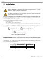
Check the ATEX CE marking on the nameplate of the machine and verify that it meets the conditions of
the order.
Figure 1.1.: ATEX CE marking on the nameplate.
Should the marking on the machine not correspond with the order, please contact INOXPA immediately
to explain the situation.
The temperature class and the maximum surface temperature depend on the temperature of the product
to be stirred and the ambient temperature.
Temperature class for explosive gas atmospheres
Temperature
class
Product temperature
Room temperature
T4
≤ 130 °C
-20 °C to +40 °C
T3
≤ 154 °C
-20 °C to +40 °C

Installation
INOXPA S.A.U. 20.073.30.05EN · (0) 2023/06 9
Maximum surface temperature for explosive dust atmospheres
Maximum
surface
temperature
Product temperature
Room temperature
T130 °C
≤ 130 °C
-20 °C to +40 °C
T154 °C
≤ 154 °C
-20 °C to +40 °C
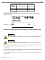
5.2. IDENTIFICATION OF THE AGITATOR
The agitator is identified using a rating plate fixed onto the motor. The type of agitator and the serial number
appear on the nameplate.
In addition to the information in the manual it should be taken into account that ATEX equipment will be
provided with the corresponding marking.
5.3. TRANSPORT AND STORAGE
According to the model, the agitators are too heavy to be stored or installed manually. Use an
appropriate mode of transport. Do not handle the agitator by the shaft as this may become deformed.
Take all possible precautions when lifting the agitator. Always use properly attached slings when
moving the agitator with a crane or other lifting device.
If the agitator is not to be installed immediately, it must be stored in an appropriate place. The shaft must be stored
in a horizontal position and placed on wooden supports or a similar material. In this position, the shaft will not
become deformed but it must not be subject to any type of load.
5.4. LOCATION
Place the agitator in such a way as to facilitate inspections and checks. Leave enough room around the agitator
for service, disassembly and maintenance operations. It is very important to be able to access the electric
connection device of the agitator, even when in operation.
It is very important to be able to access the electrical wiring and connections on the agitator, even when
it is in operation.
ATTENTION
ATTENTION
NN
01.011.32.0047
Serial number

Installation
10 INOXPA S.A.U. 20.073.30.05EN · (0) 2023/06
Please be aware that while handling any equipment with an electrical connection, a potentially explosive
atmosphere may be present, and for this reason safe work permits should be issued.
Some type of air recirculation for cooling the gear motor on the agitator must be provided.
Make sure that there are no other systems or surfaces close to the gear motor which may radiate
additional heat or may affect its cooling capacity. See instruction manual of the gear motor.
Install a separate fan, if necessary, taking into account the atmosphere in which the fan should be
operating (potentially explosive atmosphere).
Excessive temperatures
Depending on the fluid being agitated, high temperatures can be reached within and around the
agitator:
It should be taken into account that, under normal conditions, the surface temperature of the agitator is
a function of the temperature of the fluid being agitated, therefore the table of temperature classes and
maximum surface temperature in section 5.1 must be taken into account.
5.5. ELECTRICAL INSTALLATION
Before connecting the electrical motor to the mains, check local regulations on electrical safety as well as the
applicable standards.
Check the instructions manual of the manufacturer of the motor for information on how to connect it to the mains.
Take the connection of the electrical motors must be performed by qualified personnel.
Take the appropriate measures to prevent any fault.
The motor must be provided with devices for protection against power overload and short-circuits.
The agitator cannot be used in areas where there is a risk of fire or explosion when this has not been
specified in the order.
Before connecting the gear motor to the power supply, consult the supplier’s instruction manual. The
gear motor must be ATEX certified and with adequate protection for the work environment in which it is
intended to operate.
Before connecting a gear motor to the mains, check the local electrical safety regulations, as well as the
specifications of standards EN 60204-1 and EN 60079-14 currents of the moment.
Electrical equipment, terminals and components of the control systems may still bear electrical current
when they are disconnected. Making physical contact with them can endanger the safety of the operators
and the installation or cause irreparable damage to the equipment; the supplier’s instructions for the safe
opening of the gear motor must be carefully followed at all times.
Safe work permits shall be issued if the system is to be handled in the presence of potentially explosive
atmospheres; it is recommended to do this kind of work in non-classified atmospheres (no explosive
atmosphere can be present at the location of the agitator during its handling).
Follow the gear motor manufacturer's instructions at all times.
The switchgear must comply with all applicable regulations, as stipulated in the electrical safety
regulations as well as the directions laid down by the manufacturer of the ATEX gear motor.
In addition, overload protections suitable for the gear motor power rating must be installed on the gear
motor.

Installation
INOXPA S.A.U. 20.073.30.05EN · (0) 2023/06 11
5.6. ASSEMBLY
To locate and fix the agitator in the support flange of the tank, the propeller must be removed from the shaft. Once
the base of the agitator is placed on the supporting flange, the fixing nuts and screws will be assembled in their
corresponding holes, without being tightened. When this operation has been carried out, the agitator must be
levelled using the following method:
1. place a spirit level against the shaft.
2. check 4 points at 90º to each other around the circumference of the shaft and at the same height.
3. once the shaft is level, firmly tighten the fixing nuts and screws. Finally, the propeller is mounted on the
end of the shaft. Be careful when assembling the shaft not to hit or strain it so as to avoid it being bent.
Force should never be applied to the end of the agitator shaft, as it can easily suffer permanent
damage.
Check the alignment of the agitator shaft with the half shaft once its assembly is completed.
ATEX agitators are very compact machines and are always supplied together with the drive.
ATTENTION
ATTENTION

Start-up
12 INOXPA S.A.U. 20.073.30.05EN · (0) 2023/06
6. Start-up
The start-up of the agitator can be carried out provided the instructions indicated in the chapter 5.
Installation.
• Check that the power supply matches the rating indicated on the motor plate.
• Check the alignment of the agitator shaft.
• Cheºck the level of fluid in the tank. When not specified in the order, the agitator cannot be operated during
the filling or emptying of the tank.
• All the guards must be in place.
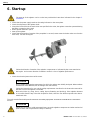
• Start up the agitator.
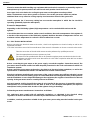
• Check that the direction of rotation of the propellers is correct (it must rotate clockwise when see form the
drive side). See the next figure:
Follow the direction of rotation of the agitation components as indicated by the arrow attached to
the engine. An incorrect direction of rotations results in a loss of agitation performance.
• Check the electrical power draw of the motor.
Do not modify the operating parameters for which the agitator was initially designed without written
authorisation from INOXPA (risk of damage and user hazard).
Follow the instructions for use and the safety requirements described in the instructions manual for
the tank in which the agitator is mounted.
Mechanical risks (e.g. drag, shear, cutting, impact, flattening and pinching). If the agitation element
is accessible from the top or the tank inspections hatch, then the user will be exposed to the above-
mentioned risks.
The tank must be fitted with protective devices and safety equipment. Consult the manufacturer’s instructions
manual.
Introducing an object or solid raw material may cause the agitation component and other mechanical
parts to break and compromise its safety or warranty.
ATTENTION
ATTENTION
20.073.32.0021

Start-up
INOXPA S.A.U. 20.073.30.05EN · (0) 2023/06 13
Explosive atmospheres may be generated during the start-up of the agitator, and safe work permits
should be issued for this purpose. These tasks shall only be carried out by qualified or trained personnel.
Do not modify the operating parameters initially set for the agitator, according to ATEX Form
sheet; since this could result in deterioration and the risk of formation of explosive atmospheres
and ignition sources, placing the operator in danger.
The agitator cannot operate with no fluid in the tank. Therefore, a safety system is required to ensure a
minimum fluid level of 350 mm above the top blade when the agitator is running.

Troubleshooting
14 INOXPA S.A.U. 20.073.30.05EN · (0) 2023/06
7. Troubleshooting

Maintenance
INOXPA S.A.U. 20.073.30.05EN · (0) 2023/06 15
8. Maintenance
8.1. GENERAL CONSIDERATIONS
This agitator, just like any other machine, requires maintenance. The instructions contained in this manual cover
the identification and replacement of spare parts. The instructions are aimed at maintenance personnel and those
responsible for the supply of spare parts.
Maintenance of any equipment intended for use in potentially explosive atmospheres shall only be carried
out in conjunction with the use of safe work permits as specified in Directive 1999/92/EC.
Carefully read chapter 9. Technical Specifications.
Maintenance work can only be carried out by qualified personnel that are trained and equipped with
the necessary resources to carrying out this work.
Before beginning maintenance work, ensure that the electric motor is disconnected and that the tank
is empty.
All parts or materials that are replaced must be properly disposed of/recycled in accordance with the
current directives applicable in each area.
Before beginning maintenance work, ensure that the agitator is disconnected.
8.2. MAINTENANCE
• Inspect the agitator regularly.
• Do not fail to keep the agitator clean.
• Check the state of the motor or the gear motor.
• Check the state of the bearings.
• Check the sealing: seal and/or lip seal.
Motor or gear motor maintenance shall be carried out in accordance with the manufacturer’s instructions, see the
instructions manual.
The possible presence or generation of explosive atmospheres should be taken into account during
maintenance work, and safe work permits should therefore be used accordingly.
Maintenance of the gear motor shall be performed according to the manufacturer's specifications; refer
to the manufacturer's instruction manual.
Use tools which are technically suitable for the specific maintenance and repair work involved. If the area
is not declassified, all the tools used must be non-sparking and safe work permits shall be required.
In the case of painting the parts of the agitator (except drive), the type of paint to be used must be
conductive, dissipative or antistatic insulating, so that no accumulation of charges occurs or, if yes, these
are controlled (paint must have a surface resistivity < or = 1 Gohm).
8.3. LUBRICATION
Follow the manufacturer’s indications when lubricating the geared motor’s bearings.
8.4. SPARE PARTS
To order spare parts it is necessary to indicate the type and serial number included on the agitator’s characteristics
plate, as well as the position and description of the part as found in chapter 9. Technical Specifications.
To request spare parts for an agitator intended to work in a classified zone, it is necessary to explicitly
indicate in the order that it is an ATEX agitator and include the manufacturing number.

Maintenance
16 INOXPA S.A.U. 20.073.30.05EN · (0) 2023/06
If the spare parts are not requested in this way, Inoxpa shall not be responsible for the case that the
agitator may not operate with parts which are not suitable for the classified zone where is installed.
8.5. CONSERVATION
If the agitator is out of service for a considerable period of time, clean and treat the parts with VG46 mineral oil.
The shaft must be stored in the horizontal position and on wooden supports or on supports of a similar material.
8.6. CLEANING
The use of aggressive cleaning products such as caustic soda and nitric acid may give raise to skin
burns.
Use rubber gloves during cleaning procedures.
Always use protective goggles.
8.6.1. Automatic CIP (clean-in-place)
8.6.2. Automatic SIP (sterilization-in-place)
8.7. DISASSEMBLY AND ASSEMBLY OF THE AGITATOR
Disassembly or assembly of any equipment intended for use in potentially explosive atmospheres shall
only be carried out in conjunction with the use of safe work permits as specified in the Directive
1999/92/EC.
Both the assembly and disassembly of agitators must be performed by qualified personnel, using only
appropriate tools, as well as suitable working methods.
Use tools which are technically suitable for the specific maintenance and repair work involved. If the area
is not declassified, all tools must be non-sparking and safe work permits must be issued.
Incorrect assembly or disassembly may cause the agitator to malfunction and lead to high repair costs
and a long down-time period, even invalidating the system's protection systems.
INOXPA is not responsible for accidents or damages caused by failure to comply with the instruction
manual and with this annex.
Cleaning
Before disassembling the agitator, it must be cleaned both on the outside and on the inside. Furthermore,
the possible presence or formation of explosive atmospheres should be taken into account, and safe
work permits should therefore be used accordingly.
The disassembly and assembly of the agitators should only be carried out by qualified personnel
using only appropriate tools. Ensure that staff read these instructions manual attentively, particularly
the instructions that relate to their work.
Stop the motor from starting up when carrying out assembly and disassembly work on the agitator.
Place the agitator switch in the “off” position.
Lock out the electrical switchboard or place a warning sign.
Remove the fuses and take them to the workplace.
8.7.1. Disassembly of the agitator
8.7.2. Assembly of the agitator

Technical Specifications
INOXPA S.A.U. 20.073.30.05EN · (0) 2023/06 17
9. Technical Specifications
9.1. MATERIALS
Parts in contact with the product
1.4404 (AISI 316L)
Other steel parts
1.4307 (AISI 304L)
Elastomers
EPDM
Sealing system
C/SiC/EPDM
Surface finish
Ra ≤ 0,8 μm
Working pressure
-1 to 10 bar
Working temperature
-5 to 130 °C
Temperature range. See section 5.1.
9.2. OTHER FEATURES
9.3. DIMENSIONS
9.4. PARTS LIST

Page is loading ...
Page is loading ...
-
 1
1
-
 2
2
-
 3
3
-
 4
4
-
 5
5
-
 6
6
-
 7
7
-
 8
8
-
 9
9
-
 10
10
-
 11
11
-
 12
12
-
 13
13
-
 14
14
-
 15
15
-
 16
16
-
 17
17
-
 18
18
-
 19
19
-
 20
20
-
 21
21
-
 22
22


Ask a question and I''ll find the answer in the document
Finding information in a document is now easier with AI
Related papers
Other documents
-
Carlisle Agitators for Drums User manual
-
 Wiwa GX Series Operating instructions
-
 Hardi ZATURN Instruction book
-
Binks Agitators-Direct Drive User manual
-
-
 Binks Pressure Tanks User manual
-
-
Hobart N50 MIXER User manual
-
-


