Page is loading ...

www.bdsensors.com
EN
Operating Manual
Differential Pressure Transmitter DMD 831
Eastern Europe
BD SENSORS s.r.o.
Hradišťská 817
CZ - 687 08 Buchlovice
Czech Republic
Tel.: +420 572 411 011
Fax: +420 572 411 497
Headquarters
BD SENSORS GmbH
BD-Sensors-Str. 1
D - 95199 Thierstein
Germany
Tel.: +49 (0) 9235-9811-0
Fax: +49 (0) 9235-9811-11
Russia
BD SENSORS RUS
39a, Varshavskoe shosse
RU - Moscow 117105
Russia
Tel.: +7 (0) 95-380 1683
Fax: +7 (0) 95-380 1681
China
BD SENSORS China Co, Ltd.
Room B, 2nd Floor, Building 10,
No. 1188 Lianhang Rd.
201112 Shanghai,
China
Tel.: +86 (0) 21-51600 190
Fax: +86 (0) 21-33600 613
further agencies in:
EUROPE
• Belgium
• Denmark
• Finland
• France
• Great Britain
• Greece
• Italy
• Lithuania
• Luxemburg
• Netherlands
• Norway
• Poland
• Portugal
• Romania
• Sweden
• Switzerland
• Slovakia
• Spain
• Turkey
• UK
• Ukraine
AFRICA
• Egypt
• South Africa
ASIA
• India
• Iran
• Israel
• Japan
• Kazakhstan
• Malaysia
• Singapore
• Taiwan
• Thailand
• Vietnam
AUSTRALIA
The addresses of our distribution partners are listed on
our homepage www.bdsensors.com. It is possible to
download data sheets, operating manuals, ordering
codes and certificates, as well.
Table of contents
1. General information
2. Product identification
3. Mechanical installation
4. Electrical Installation
5. Initial start-up
6. Operation
7. Placing out of service
8. Correction of defects
9. Recalibration
10. Maintenance
11. Return
12. Disposal
13. Warranty conditions
14. Declaration of conformity / CE
1. General information
1.1 Information on the operating manual
This operating manual contains important information on
proper usage of the device. Read this operating manual
carefully before installing and starting up the pressure
measuring device.
Adhere to the safety notes and operating instructions
which are given in the operating manual. Additionally ap-
plicable regulations regarding occupational safety, acci-
dent prevention as well as national installation standards
and engineering rules must be complied with!
This operating manual is part of the device, must be kept
nearest its location, always accessible to all employees.
This operating manual is copyrighted. The contents of this
operating manual reflect the version available at the time
of printing. It has been issued to our best knowledge. BD
SENSORS is not liable for any incorrect statements and
their effects.
– Technical modifications reserved –
1.2 Symbols used
DANGER
! – dangerous situation, which may re-
sult in death or serious injuries
WARNING
! – potentially dangerous situation,
which may result in death or serious injuries
CAUTION
! – potentially dangerous situation,
which may result in minor injuries
CAUTION
! – potentially dangerous situation,
which may result in physical damage
NOTE – tips and information to ensure a failure-free
operation
1.3 Target group
WARNING
! To avoid operator hazards and dam-
ages of the device, the following instructions have to
be worked out by qualified technical personnel.
1.4 Limitation of liability
By non-observance of the operating manual, inappropri-
ate use, modification or damage, no liability is assumed
and warranty claims will be excluded.
1.5 Intended use
- The differential pressure transmitters DMD 831 are
planned for industrial uses. The compact construc-
tion form of the differential pressure transmitter per-
mits the easy integration also in arrangements and
machines with limited place relations.
- Base elements of the DMD 831 are two piezoresis-
tive stainless steel sensors.
- With on both sides pressure admission, the differ-
ence of the pressure will be formed between positive
and negative side and will be converted into a pro-
portional electric signal.
- The DMD 831 is used among other things in the ma-
chine construction and plant construction for the filter
supervision and flow measurement as well as in hy-
draulic uses.
- As measuring media are acceptable the liquids and
the gases, which are suited with the seal material as
well as stainless steel 1.4404 and 1.4435.
- It is the operator's responsibility to check and verify
the suitability of the device for the intended applica-
tion. If any doubts remain, please contact our sales
department in order to ensure proper usage. BD
SENSORS is not liable for any incorrect selections
and their effects!
- The technical data listed in the current data sheet are
engaging and must be complied with. If the data
sheet is not available, please order or download it
from our homepage. (http://www.bdsensors.com)
WARNING
! – Danger through improper usage!
1.6 Package contents
Please verify that all listed parts are undamaged included
in the delivery and check for consistency specified in your
order:
- Differential Pressure Transmitter DMD 831
- Mounting bracket + 2 screws
- Operating Manual DMD 831
2. Product identification
The device can be identified by its manufacturing label. It
provides the most important data. By the ordering code
the product can be clearly identified. The programme ver-
sion of the firmware, (e. g. P07) will appear for about 1
second in the display after starting up the device. Please
hold it ready for inquiry calls.
Fig. 1 manufacturing label- example
!
The manufacturing label must not be removed from
the device!
3. Mechanical installation
3.1 Mounting and safety instructions
WARNING!
Install the device only when current-
less!
WARNING!
This device may only be installed by
qualified technical personnel who has read and un-
derstood the operating manual!
!
Handle this high-sensitive electronic precision
measuring device with care, both in packed and
unpacked condition!
!
There are no modifications/changes to be made on
the device.
!
Do not throw the package/device!
!
Remove packaging only directly before starting up
the device to avoid any damage!
!
Do not use any force when installing the device to
prevent damage of the device and the transmitter!
!
The display and the plastic housing are equipped
with rotational limiters. Please do only rotate the dis-
play or the housing within the limit.
3.2 General installation steps
- Carefully remove the pressure measuring device
from the package and dispose of the package
properly.
- Connect the reference pressures according to the
following mounting steps, conformable of your
mechanical connections. It is important to note
that:
- the higher pressure must be connected at the
input "+"
- the lower pressure must be connected at the
input "-"
3.3 Installation steps according to DIN 3852
DO NOT USE ANY ADDITIONAL SEALING MATE-
RIALS, LIKE YARN, HEMP OR TEFLON TAPE!
- Control both mechanical connections, whether the
o-ring properly sits in the groove.(o-rings belong to
the scope of supply.)
- Ensure that the sealing surface of the taking part is
perfectly smooth and clean. (RZ 3.2)
- Screw the device into the corresponding thread by
hand.
- Hold on the DMD 831 with a hand to the key surface
SW 27 of the respective mechanical connection and
tighten your fittings successively (wrench size of
steel: G1/4": approx. 5 Nm; G1/2": approx. 10 Nm).
- The indicated tightening torques must not be ex-
ceeded!
3.4 Installation steps according to EN 837
- Use a suitable seal, corresponding to the medium
and the pressure input (e. g. a copper gasket).
- Ensure that the sealing surface of the taking part is
perfectly smooth and clean. (RZ 6.3)
- Screw the device into the corresponding thread by
hand.
- Tighten it with a wrench (for G1/4": approx. 20 Nm;
for G1/2": approx. 50 Nm).
- The indicated tightening torques must not be ex-
ceeded!
3.5 Installation steps for NPT
- Use a suitable seal (e. g. a PTFE-strip).
- Screw the device into the corresponding thread by
hand.
- Tighten it with a wrench (for 1/4" NPT: approx.
30 Nm; for 1/2" NPT: approx. 70 Nm).
- The indicated tightening torques must not be ex-
ceeded!
3.6 Mounting with mounting bracket
With the mounting bracket the DMD 831 can be mounted
on smooth surfaces / walls.
The mounting bracket is screwed below onto the plastic
housing of the DMD 831. Remove the blind caps and use
the added screws.
4. Electrical Installation
WARNING!
Install the device only when current-
less!
Connect the device accordingly of your electric con-
nection, with the help of the pin configuration table and
the wiring diagram, electrically.
At devices with cable gland connection as well as
cable tins, must be respected to the fact, that the
external diameter of the used wire must lie within the
allowed clamp area. Moreover, must be made sure,
that this firmly and freely of gap sits in the cable
screw connection!
4.1 Pin configuration
electrical
connections M12x1
(5-pin) cable colours
supply +
supply −
3-wire: signal +
contact 1
contact 2
1
3
2
4
5
wh (white)
bn (brown)
gn (green)
gy (gray)
pk (pink)
shield
pressure port ye/gn (yellow/
green)
4.2 Wiring diagram
For the electrical connection a shielded and twisted
multicore cable is recommended.
5. Initial start-up
At the introduction of your differential pressure transmitter
must be paid attention to the fact, that the device will be
admissioned in both mechanical connections at the same
time with the pressure. At one-side pressure admission,
the maximal allowed static pressure (one-side) should be
considered (see attached technical data).
WARNING!
Before start-up, the user has to
check for proper installation and for any visible
defects.
WARNING!
The device can be started and oper-
ated by authorized personnel only, who have read
and understood the operating manual!
WARNING!
The device has to be used within the
technical specifications, only (compare the data in
the data sheet)!
6. Operation
6.1 Operating and display elements
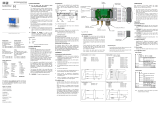
Fig. 3 service foil
The display owns to the displaying of the active switch
output for switch output 1 a green LED and for switch
output 2 (optional) a yellow LED. If someone of these
LED's shines, the respective switch point is reached
and the switch output is active.
The displaying of the measuring value as well as con-
figuring the single parameters occurs menu-driven by
a 4-figure seven segment display. The single functions
are regulated on the basis of two-front-sided arranged
miniature push buttons:
- "▲" – button: with this button you move in the
menu system forward or you raise the display
value
- "▼" – button: with this button you move in the
menu system backward or you reduce display
value.
- both buttons at the same time: if you press both
buttons at the same time, you can change
between display mode and configuration mode
and confirm a menu point or an adjusted value.
With the adjusting of the values you can raise the
countable speed, while you low-spiritedly hold the
respective button ("▲" or "▼") longer than 5 sec-
onds.
6.2 Configuration
The menu system is closed in itself, so that someone can
turn the leaves forward as well as backward by the single
setting menus to reach to the desired setting point. All
settings are stored permanently in an EEPROM and are
available therefore also after separation of the supply
again. The menu system and the menu points were
formed so simply as possible. In the following every single
menu point is described in detail by which an easy and a
quick configuration of your device are possible. The con-
struction of the menu systems differs by the fact, that the
grey deposited menus are available only with two switch
outputs or analog output.
Please keep exactly to the descriptions and note
that changes become effective in the adjustable
parametres (switch on point, switch off point etc.)
only after activity of both buttons and after
abandonment of the menu point.
6.3 Password system
The terminal box is provided with an access protection,
so that the menu system can be served only by the
authorized person.
- If you activate the password, the complete menu sys-
tem is closed.
- If the access protection is lifted by the password, the
complete menu is released.
You can activate the password about menu "PAon"
or "PAof" and deactivate.
You can change the password about the special
menu 4.
For the case that the password has got lost there is
a possibility, to put this back. This is possible, while
you restore the work settings with the help of the spe-
cial menu 3.
6.4 Unit
The unity of the shown measuring value is already fixed
at the time of the order by the desired measuring area.
6.5 Configuration example of analogue output (op-
tional)
With the help of the menus ZP and EP the analog output
can be configured (if available). In the following, the func-
tion of these menus should be made clear at an example:
Accepted someone has a differential pressure transmit-
ter with a nominal pressure range 0... 6 bar, which is con-
nected to P1. The analogous signal amounts to 4 ... 20
mA / 3-wire and were configured in the menu 26 "SiAn"
on "P1".
Factory-sided, the following signal behavior is put:
0 bar = 4.00 mA 3 bar = 12.00 mA 6bar= 20 mA
If someone changes the value in the menu ZP from 0 to
1 and the value in the menu EP from 6 to 5, the following
signal behavior will appear:
1 bar = 4.00 mA 3 bar = 12.00 mA 5bar= 20 mA
The values of the menus ZP and EP are adjusta-
ble up to the relation 1:10 of the nominal pressure
range.
6.6 Hysteresis and comparing mode
To invert the respective modes, you have to exchange
the values for the switch-on and switch-off points.
Fig. 4 compare mode Fig. 5 compare mode
inverted
Fig. 6 hysteresis mode Fig. 7 hysteresis mode
inverted
V
S
input "p-" input "p+"
type - ordering serial-
code number
nominal
range
differential
pressure
range
signal
and
supply

BA_DMD831_E_sro_18.09.2018
6.6. Structure of the menu system 6.7 Menu list 7. Placing out of service
WARNING!
When dismantling the device, it must
always be done in the depressurized and currentless
condition! Check also if the medium has to be
drained off before dismantling!
WARNING!
Depending on the medium, it may
cause danger for the user. Comply therefore with ad-
equate precautions for purification.
8. Correction of defects
9. Recalibration
During the life span of the device it can seem that the off-
set moves. This can lead to the fact that a divergent signal
value covered to the opposed measuring area beginning
is given.
It is also possible that the span value (Full-Scale) moves.
This would lead to the fact that one signal value divergent
from the opposed measuring area end is given.
Should one of these both phenomena appear, after longer
use, a recalibration is recommended to be able to guar-
antee and furthermore high exactness.
For the recalibration, please send your device to BD SEN-
SORS.
10. Maintenance
In principle, this device is maintenance-free. If desired,
the housing of the device can be cleaned when switched
of using a damp cloth and non-aggressive cleaning solu-
tions.
11. Return
Before every return of your device, whether for
recalibration, decalcification, modifications or repair, it
has to be cleaned carefully and packed shatter-proofed.
You have to enclose a notice of return with detailed defect
description when sending the device. If your device came
in contact with harmful substances, a declaration of
decontamination is additionally required. Appropriate
forms can be downloaded from our homepage
www.bdsensors.com. Should you dispatch a device
without a declaration of decontamination and if there are
any doubts in our service department regarding the used
medium, repair will not be started until an acceptable
declaration is sent.
If the device came in contact with hazardous
substances, certain precautions have to be
complied with for purification!
12. Disposal
The device must be disposed according to the
European Directives 2002/96/EG and
2003/108/EG (on waste electrical and elec-
tronic equipment). Waste of electrical and
electronic equipment may not be disposed by
domestic refuse!
WARNING! Depending on the measuring medium,
deposit on the device may cause danger for the user
and the environment. Comply with adequate precau-
tions for purification and dispose of it properly.
13. Warranty conditions
The warranty conditions are subject to the legal warranty
period of 24 months from the date of delivery. In case of
improper use, modifications of or damages to the device,
we do not accept warranty claims. Damaged diaphragms
will also not be accepted. Furthermore, defects due to
normal wear are not subject to warranty services.
14. Declaration of conformity / CE
The delivered device fulfils all legal requirements.
The applied directives, harmonised standards and docu-
ments are listed in the EC declaration of conformity, which
is available online at http://www.bdsensors.com.
Additionally, the operational safety is confirmed by the CE
sign on the manufacturing label.
menu 1
–
access protection
PAon password active to deactivate: set password
PAof password inactive to activate: set password
default setting for the password is „0005“; modification of the password is described in special menu 2
menu 2
–
displaying of measuring range start
defined by order; no input option
m
enu 3
–
displaying of measuring range end
defined by order; no input option
menu 4 and 5
–
set zero point / end point
The configuration of the zero point causes a changing of the analogue output, whereas the display value remains
unchanged. (zero and end point can be configured within the limits of the nominal pressure range, according to the
manufacturing label)
menu 6
–
setting of damping (f
ilter)
this function allows getting a constant display value although the measuring values may vary considerably; the
time constant for a simulated low-pass filter can be set (0.3 up to 30 sec permissible)
menu 7
–
activation of overstepping report
set "on" or "off"
menu 8
–
signal choosing of switch output 1
P1", "P2" (the switch point reacts to the static pressure at the suitable input) or "DIFF" (difference pressure
between P1 and P2)
menu 9
–
setting
of switch
-
on point (switch output 1)
set value for activation of contact 1 (S1on)
menu
10
–
set
ting of switch
-
off point
(switch output 2)
set value for deactivation of contact 1 (S1oF)
menu 11
–
signal choosing of switch output 2
P1", "P2" or "DIFF"
menu 12
–
setting of switch
-
on point (switch output 2
)
set value for activation of contact 2 (S2on)
menu 13
–
setting of switch
-
off point (switch output 2)
set value for deactivation of contact 2 (S2oF)
menu 14
–
selecting hysteresis or comparing mode
(switch output 1)
for switch output set 1 hysteresis mode (HY 1) or comparing mode (CP 1)
compare "6.6 hysteresis and comparing mode"
menu 15
–
selecting hysteresis or comparing mode (switch output
2)
for switch output set 2 hysteresis mode (HY 2) or comparing mode (CP 2)
compare "6.6 hysteresis and comparing mode"
menu
16
–
setting of switch on
delay (switch point 1
)
set the value of switch on delay after reaching contact 1 (d1on); (0 up to 100 sec permissible)
menu 17
–
setting of switch off delay (switch point 1)
set the value of switch off delay after reaching contact 1 (d1oF); (0 up to 100 sec permissible)
menu 18
–
setting of switch on delay (switch point 2)
set the value of switch on delay after reaching contact 2 (d2on); (0 up to 100 sec permissible)
menu 19
–
setting of switch off delay (switch point 2
)
set the value of switch off delay after reaching contact 2 (d2on); (0 up to 100 sec permissible)
menu 20 and 21
–
maximum / minimum value display
view high pressure (HiPr) or low pressure (LoPr) during the measurement process (the value will not remain stored
if the power supply is interrupted)
to erase: push both buttons again within one second
menu 22
–
measured value actualization (display)
set the length of the update cycles for the display (0.0 up to 10sec permissible)
menu 23
–
simulation switch output 1
state of the switch point 1 can be simulated; with the buttons "▲" and "▼", the switch output 1 can be activated or
be deactivated
menu 24
–
simulation switch output 2
state of the switch point 2 can be simulated; with the buttons "▲" and "▼", the switch output 2 can be activated or
be deactivated
menu 25
–
simulation analog output
signal value of the analog output can be simulated; choice between "oi 4" (4 mA or 2 V), "oi12" (12 mA or 6 V) and
"oi20" (20 mA or 10 V)
menu 26
–
signal
choosing analog output
assignment to the analog output the desired input signal; if "P1" or "P2" is put, the analog output follows the static
pressure at the suitable input. With the setting "DIFA", "DIFB" and “DIFC” the analog output follows the calculated
difference pressure from P1 and P2. With "DIFB" a movement of the analogous signal occurs, in addition, about
50% FSO upwards, with “DIFC” a differential signal with square-root extraction occurs
menu 27
–
error signal definition
fixing the mistake signal, which is given with a device defect; choice between "0FF" (no mistake signal call sign),
"C 0" (0 mA or 0 V), "C L0" (3.5 mA or 1.75 V) and "C HI" (23 mA or 11.5 V)
an issue of the mistake signal only occurs if the menu 6 "HILo" on "on" was put
menu 28
–
position correction / offset
adjustment
A position correction or an offset's comparison can be carried out only with availability of suitable reference
source,
in so far as the measuring value deviation lies within certain borders; confirm the menu point "P0SI" by pressing
both buttons. If the offset deviates from the environment pressure, it is necessary to connect the pressure refer-
ence, which corresponds to the measuring start value in P1. P2 must stay open! If you press afterwards again both
buttons, the signal topically spent by the differential pressure transmitter, will be stored as an offset. Now in the
display appears the adjusted measuring start value (Zero Point), although the sensor signal is shifted in the offset.
Note that with available analog output, this remains untouched of the carried out change.
Furthermore a movement of the span value (Full Scale) is also carried out at the same time, with the move-
ment of the offset.
menu 29
–
load of factory default setting
With this menu carried out changes can be cancelled before. Please note that also the password will be put back.
menu 30
–
display mode
assigning to the display value the desired input signal (P1", "P2" or "DIFF")
menu 31
–
configuration load
loading of stored device configurations (choice between number 1 to 5)
menu 32
–
configuration store
storing of device configurations (number 1 to 5 is available)
Special menu
(to access a special menu, select the menu item „PAof“ with the ▲- or ▼-button an confirm it; “1” appears in display)
s
pecial menu 1
–
span
adjustment
The menu serves for the correction of the display with divergent span. Necessarily, this comparison becomes, if
the displayed measuring value differs from the enclosed pressure value. A span comparison can be carried out
only with availability of suitable reference sources, provided that the measuring value divergence lies within certain
borders. To the display correction with divergent span, you should put with the button "▲" or "▼" the number
"0238". To confirm the setting, press both buttons at the same time. "FS S" appears in the display. Now it is
necessary to connect the pressure reference, which corresponds to the measuring range end value, to P1. P2
must stay open! If you press afterwards again both buttons, the signal topically spent by the differential pressure
transmitter will be stored as a span signal. In the display the adjusted measuring range end value (End Point)
appears from this time, although the sensor signal is shifted
in the span signal.
Please note that the analogous output signal (with available analog output) remains untouched from this
change.
special menu 2
–
password setting
set "0835"; confirm by pressing both buttons, "SEtP" appears in display; put now with "▲" or "▼" - button your
password. You can choose this freely (0... 9999; excluded are the code numbers 0238, 0247, 0729 and 0835). At
last you should confirm your password by
concurrent pressure of both buttons.
failure
possible cause
error detection / redress
no source signal - wrong connected
- wire break
- defective measuring
instrument (signal input)
- check the connections
- check all wire connections which are ne-
cessary to the supplying of the device
(including the plugs)
- check the ammeter (fine protection) or
the analogous entrance of your signal
processing unity
analog output signal too
small - load resister too high
- the supply too low
- defective energy supply
- check the value of load resister
- check the exit tension of power supply
- check the power supply unit and the
supply tension on input
movement of the output
signal - the membrane of the measuring cell
has got dirty or damaged - the device should be sent for repair to
BD SENSORS
wrong or no output signal - damaged electric connection
- wrong polarity of the enclosed pres-
sures
- check the connection
- check whether the higher pressure is
connected in "+"
If you ascertain a mistake, you should try to repair this with the help of the above table, or send in the device to the repair
to our
service address.
Repair in the device may be carried out only by the
manufacturer!
/
