Mitsubishi Electric XD3500U User manual
- Category
- Data projectors
- Type
- User manual
This manual is also suitable for


EN-2
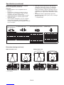
CAUTION
RISK OF ELECTRIC SHOCK
DO NOT OPEN
CAUTION: TO REDUCE THE RISK OF ELECTRIC
SHOCK, DO NOT REMOVE COVER (OR BACK)
NO USER-SERVICEABLE PARTS INSIDE
REFER SERVICING TO QUALIFIED SERVICE
PERSONNEL.
The lightning fl ash with arrowhead symbol within an equilateral triangle is intended to alert
the user to the presence of uninsulated “dangerous voltage” within the product’s enclosure
that may be of suffi cient magnitude to constitute a risk of electric shock.
The exclamation point within an equilateral triangle is intended to alert the user to the
presence of important operating and maintenance (servicing) instructions in the literature
accompanying the appliance.
WARNING:
TO PREVENT FIRE OR SHOCK HAZARD, DO NOT EXPOSE THIS APPLIANCE TO RAIN OR MOISTURE.
CAUTION:
TO PREVENT ELECTRIC SHOCK, DO NOT USE THIS (POLARIZED) PLUG WITH AN EXTENSION CORD,
RECEPTACLE OR OTHER OUTLET UNLESS THE BLADES CAN BE FULLY INSERTED TO PREVENT BLADE
EXPOSURE.
NOTE:
SINCE THIS PROJECTOR IS PLUGGABLE EQUIPMENT, THE SOCKET-OUTLET SHALL BE INSTALLED NEAR
THE EQUIPMENT AND SHALL BE EASILY ACCESSIBLE.
WARNING
Use the attached specifi ed power supply cord. If
you use another power supply cord, it may cause
interference with radio and television reception.
This apparatus must be grounded.
DO NOT LOOK DIRECTLY INTO THE LENS WHEN
THE PROJECTOR IS IN THE POWER ON MODE.
CAUTION
Not for use in a computer room as defi ned in the
Standard for the Protection of Electronic Computer/
Data Processing Equipment, ANSI/NFPA 75.

EN-3
Contents
Important safeguards ........................................................................................................................4
Preparing your projector ....................................................................................................................6
Using the remote control ...................................................................................................................9
Setting up your projector .................................................................................................................10
Viewing computer images ...............................................................................................................13
Viewing video images ......................................................................................................................19
Menu operation ...............................................................................................................................25
Adjusting projected images .............................................................................................................33
Advanced features ..........................................................................................................................37
Indicators .........................................................................................................................................42
Replacing the lamp .........................................................................................................................43
Maintenance ....................................................................................................................................45
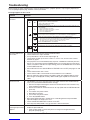
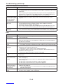
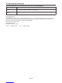
Troubleshooting ...............................................................................................................................46
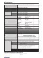
Specifi cations ..................................................................................................................................50
Trademark, Registered trademark
• DLP™, Digital Micromirror Device, DMD and BrilliantColor™ are all trademarks of Texas Instruments.
• HDMI, the HDMI logo and High-Defi nition Multimedia Interface are trademarks or registered trademarks of HDMI
Licensing LLC.
• Macintosh is registered trademark of Apple Computer Inc.
• The trademark of PJLink is trademark applied for registration or registered trademark in Japan, the United States,
and other countries and areas.
• Other brand or product names are trademarks or registered trademarks of their respective holders.

EN-4
Important safeguards
Please read all these instructions regarding your
projector and retain them for future reference. Follow
all warnings and instructions marked on the projector.
1. Read instructions
All the safety and operating instructions should be
read before the appliance is operated.
2. Retain instructions
The safety and operating instructions should be
retained for future reference.
3. Warnings
All warnings on the appliance and in the operating
instructions should be adhered to.
4. Instructions
All operating instructions must be followed.
5. Cleaning
Unplug this projector from the wall outlet before
cleaning it. Do not use liquid aerosol cleaners. Use
a damp soft cloth for cleaning.
6. Attachments and equipment
Never add any attachments and/or equipment
without the approval of the manufacturer as such
additions may result in the risk of fi re, electric
shock or other personal injury.
7. Water and moisture
Do not use this projector near water or in contact
with water.
8. Accessories
Do not place this projector on an unstable cart,
stand, tripod, bracket or table. Use only with a
cart, stand, tripod bracket, or table recommended
by the manufacturer or sold with the projector.
Any mounting of the appliance should follow
the manufacturer’s instructions and should use
a mounting accessory recommended by the
manufacturer.
10. Power sources
This projector should be operated only from the
type of power source indicated on the marking
label. If you are not sure of the type of power,
please consult your appliance dealer or local
power company.
11. Power-cord protection
Power-supply cords should be routed so that
they are not likely to be walked on or pinched
by items placed upon or against them. Pay
particular attention to cords at plugs, convenience
receptacles, and points where they exit from the
appliance. Do not put the power cord under a
carpet.
12. Overloading
Do not overload wall outlets and extension cords
as this can result in a fi re or electric shock.
13. Objects and liquids
Never push objects of any kind through openings
of this projector as they may touch dangerous
voltage points or short-out parts that could result
in a fi re or electric shock. Never spill liquid of any
kind on the projector.
14. Servicing
Do not attempt to service this projector by yourself.
Refer all servicing to qualifi ed service personnel.
15. Damage requiring service
Unplug this projector from the wall outlet and refer
servicing to qualifi ed service personnel under the
following conditions:
(a) If the power-supply cord or plug is damaged.
(b) If liquid has been spilled, or objects have fallen
into the projector.
(c) If the projector does not operate normally after
you follow the operating instructions. Adjust
only those controls that are covered by the
operating instructions. An improper adjustment
of other controls may result in damage and
may often require extensive work by a qualifi ed
technician to restore the projector to its normal
operation.
(d) If the projector has been exposed to rain or
water.
(e) If the projector has been dropped or the
cabinet has been damaged.
(f)
If the projector exhibits a distinct change in
performance - this indicates a need for service.
16. Replacement parts
When replacement parts are required, be sure
that the service technician has used replacement
parts specifi ed by the manufacturer or parts
having the same characteristics as the original
part. Unauthorized substitutions may result in fi re,
electric shock or other hazards.
17. Safety check
Upon completion of any service or repair to this
projector, ask the service technician to perform
safety checks determining that the projector is in a
safe operating condition.
An appliance and cart combination should be
moved with care. Quick stops, excessive force and
uneven surfaces may cause the appliance and cart
combination to overturn.
9. Ventilation
Slots and openings in the cabinet are provided
for ventilation, ensuring reliable operation of the
projector and to protect it from overheating. Do
not block these openings or allow them to be
blocked by placing the projector on a bed, sofa,
rug, or bookcase. Ensure that there is adequate
ventilation and that the manufacturer’s instructions
have been adhered to.

EN-5
Important safeguards (continued)
WARNING:
Unplug immediately if there is something
wrong with your projector.
Do not operate if smoke, strange noise or odor comes
out of your projector. It might cause fi re or electric
shock. In this case, unplug immediately and contact
your dealer.
Never remove the cabinet.
This projector contains high voltage circuitry. An
inadvertent contact may result in an electric shock.
Except as specifi cally explained in the User Manual do
not attempt to service this product by yourself. Please
contact your dealer when you want to fi x, adjust or
inspect the projector.
Do not modify this equipment.
It can lead to fi re or electric shock.
Do not keep using the damaged projector.
If the projector is dropped and the cabinet is
damaged, unplug the projector and contact your
dealer for inspection. It may lead to fi re if you keep
using the damaged projector.
Do not face the projector lens to the sun.
It can lead to fi re.
Use correct voltage.
If you use incorrect voltage, it can lead to fi re.
Do not place the projector on uneven surface.
Place the projection on a leveled and stable surface
only. Please do not place equipment on unstable
surfaces.
Do not look into the lens when it is operating.
It may hurt your eyes. Never let children look into the
lens when it is on.
Do not touch the air outlet grille and bottom
plate, which become hot.
Do not touch them or put other equipment in front
of the air outlet grille. The air outlet grille and bottom
plate, when heated, may cause injury or damage to
other equipment. Also, do not set the projector on the
desk which is easily affected by heat.
Do not look into the air outlet grille when
projector is operating.
Heat, dust, etc. may blow out of it and hurt your eyes.
Do not insert your fi ngers in the space
between the lens and the cabinet.
The lens may shift causing injury or damage to the
projector.
Do not block the air inlet and outlet grilles.
If they are blocked, heat may be generated inside the
projector, causing deterioration in the projector quality
and fi re.
Do not use fl ammable solvents (benzene,
thinner, etc.) and fl ammable aerosols near the
projector.
Flammable substances may ignite causing fi re or
breakdown because the temperature inside the
projector rises very high while the lamp is illuminating.
Do not use the projector with condensation on it.
It can lead to breakdown or other failure.
Place of installation
For safety’s sake, refrain from setting the projector
at any place subjected to high temperature and high
humidity. Please maintain an operating temperature,
humidity, and altitude as specifi ed below.
• Operating temperature: between +41°F (+5°C) and
+95°F (+35°C)
• Operating humidity: between 30% and 90%
• Never put any heat-producing device under the
projector so that the projector does not overheat.
• Do not attach the projector to a place that is
unstable or subjected to vibration.
• Do not install the projector near any equipment that
produces a strong magnetic fi eld. Also refrain from
installing near the projector any cable carrying a
large current.
• Place the projector on a solid, vibration free
surface; otherwise it may fall, causing serious injury
to a child or adult, and serious damage to the
product.
• Do not stand the projector; it may fall, causing
serious injury and damage to the projector.
• Slanting the projector more than ±10° (right and
left) or ±15° (front and rear) may cause trouble or
explosion of the lamp.
• Do not place the projector near air-conditioning
unit, heater, or humidifi er to avoid hot or moist air
to the exhaust and ventilation hole of the projector.
Upon Continuous Operation
Please ensure to power off at least for 1 hour once
every 7 days of continuous use.

EN-6
Preparing your projector
1
2
3
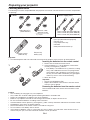
Checking accessories
The following accessories are provided with this projector. Check to be sure that all of the accessories are packed in
the package.
Cables
Remote control parts
Remote control
(290P176-10)
R6 (size-AA)
battery (two)
Others
• Lens cap (attached to the projector)
• Terminal cover
• Lamp replacement tray
• CD-ROM
• Safety Manual/Quick Start up
Power supply parts
RS-232C cable
(J2552-0114-00)
RGB cable for PC
(J2552-0072-03)
Mini D-SUB
15-pin
Mini D-SUB
15-pin D-SUB
9-pin
• Used for projector control
by computer.
D-SUB
9-pin
Power cord for US (J2552-0063-00)
Power cord for EU (J2552-0066-00)
Power cord for UK (J2552-0065-00)
Important:
• The attached power cords are to be used exclusively for this product. Never use them for other products.
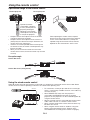
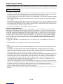
Inserting the batteries into the remote control
1. Remove the rear lid of the remote control.
2. Check the polarity (+), (-) of the batteries, and set them
correctly, inserting their (-) side fi rst.
• If the battery is inserted from the (+) side fi rst, inserting
the (-) side is diffi cult because the coil spring end hits
on the battery side. If the battery is forced to insert in
this way, the outer label of the battery may get ripped
and it may cause a short-circuit and heating.
3. Attach the rear lid.
Important:
• Use two size-AA batteries (R6).
• Replace the 2 batteries with new ones when the remote
control is slow to operate.
Removing the batteries from the remote control
Remove the back lid of the remote control and take out the
batteries.
Caution:
• Use of a battery of wrong type may cause explosion.
• Only Carbon-Zinc or Alkaline-Manganese Dioxide type batteries should be used.
• Dispose of used batteries according to your local regulations.
• Batteries may explode if misused. Do not recharge, disassemble, or dispose of them in fi re.
• Be sure to handle the batteries according to the instructions.
• Load the batteries with its positive (+) and negative (-) sides correctly oriented as indicated on the remote control.
• Keep batteries out of reach of children and pets.
• Remove the batteries, if the remote control is not used for a long time.
• Do not combine a new battery with an old one.
• If the solution of batteries comes in contact with your skin or clothes, rinse with water. If the solution comes in
contact with your eyes, rinse them with water and then consult your doctor.

EN-7
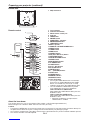
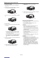
Overview
5 63 4
1 2
9 10
7 8
5
4
7
10
6
9
11
8
1
2
3
1 Control area
2 Speaker
3 Air outlet grille
4 Lens
5 Remote control sensor (front)
6 Air inlet grille
7 Remote control sensor (rear)
8 Lamp cover
9 Terminal panel
10 Air outlet grille
Caution:
Do not replace the lamp immediately after
using the projector because the lamp would
be extremely hot and it may cause burns.
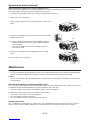
Control area
1 POWER indicator
2 COMPUTER/DVI-D/W button
3 ZOOM/FOCUS button
4 STATUS indicator
5 POWER button
6 AUTO POSITION/S button
7 ENTER/KEYSTONE button
8 VIDEO/HDMI/X button
9 VOLUME/T button
10 MENU button
11 LENS SHIFT button
12 3 4 6
16
75 8
1112 13 14 15 18 19 20109 17
1 Power jack
2 Main power switch
O: OFF I: ON
3 HDMI IN terminal (HDMI 19-pin)
4 COMPUTER/COMPONENT VIDEO DVI-D
IN (HDCP) terminal (DVI-D 24-pin)
5 AUDIO IN-1 terminal (mini jack)
6 AUDIO DVI-D terminal (mini jack)
7 DC OUT terminal (5V 1.5A MAX)
8 LAN terminal
Terminal panel
Preparing your projector (continued)
9 Kensington Security Lock Standard connector
10 Lock bar (SECURITY ANCHOR)
• Attach a chain, etc. to this lock bar to anchor the projector.
11 COMPUTER/COMPONENT VIDEO IN-1 terminal (mini D-SUB 15-pin)
12 COMPUTER/COMPONENT VIDEO IN-2 terminals (R/PR, G/Y, B/PB, H/HV, V) (BNC)
13 MONITOR OUT terminal (mini D-SUB 15-pin)
14 AUDIO OUT terminal (mini jack)
15 AUDIO IN-2 terminal (mini jack)
16 VIDEO IN and audio input terminals
17 S-VIDEO IN and audio input terminals
18 USB (COMPUTER) terminal
19 REMOTE IN and OUT terminals
20 SERIAL terminal (D-SUB 9-pin)

EN-8
1
Preparing your projector (continued)
Bottom side
1 Adjustment feet
31
COMPUTER
HDMI VIDEO
KEYSTONE AUTO POSITION
DVI-D(HDCP) S-VIDEO
FREEZE
MAGNIFY
AV MUTE
PAG E U PHOME
PAG E D OW NEND
1
2
P in P
VOLUME
4
7
8
10
11
12
13
18
19
22
23
24
25
26
27
28
6
9
14
15
517
16
29
30
CE
ASPECT
MENU ENTER
ZOOM/FOCUS LENS SHIFT LASER 21
20
R-CLICK
1
23
Remote control 1 Laser aperture
2 Transmission window
3 Wired remote control jack
4 Indicator
5 HDMI button
6 POWER button
7 COMPUTER 1, 2 buttons
8 ZOOM/FOCUS button
9 LENS SHIFT button
10 Mouse pointer
11 PAGE UP and PAGE DOWN buttons
12 MENU button
13 HOME button
14 END button
15 ASPECT button
16 CE (Color Enhancer) button
17 KEYSTONE button
18 AUTO POSITION button
19 VIDEO button
20 DVI-D(HDCP) button
21 S-VIDEO button
22 LASER button
23 S, T, W, X buttons
24 R-CLICK button
25 ENTER button
26 + , - (VOLUME) buttons
27 PinP button
28 FREEZE button
29 MAGNIFY button
30 AV MUTE button
31 Left click button
• Pressing the LASER button emits a laser beam.
Even when you keep holding down the LASER
button, it is emitted only one minute. To keep
emitting it longer, press the LASER button again.
• You can disable the LASER button to prevent
laser radiation due to misuse of the button.
How to disable the LASER button
While holding the LASER button down, press the
T button 3 times.
How to enable the LASER button
While holding the LASER button down, press the
S button 3 times.
• Whenever the batteries are replaced, the
LASER button is enabled.
About the laser beam
This remote control is a Class 2 laser product. (Max. output: 1 mW, Wavelength: 620-640 nm)
Beam Divergence: 6 m distance about 10.0 mm x 10.0 mm (±6.0 mm)
Caution:
• Pressing the LASER button on the remote control emits a laser beam. Do not look into the laser beam directly. Do
not point the laser beam at anyone. Looking at the laser beam directly may damage eyesight.
•
Use of controls or adjustments or procedures other than those specifi ed herein may result in hazardous radiation exposure.
• This remote controller cannot be repaired.

EN-9
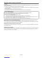
Using the remote control
30°30° 30°30°
20°
10°
20°
10°
20°
20°
Operational range of the remote control
• Keep the remote control photo-sensor out of direct
sunlight or fl uorescent lamp light.
• Keep the remote control photo-sensor at least 2 m
(6 feet) away from fl uorescent lamps. Otherwise, the
remote control may malfunction.
• If there is an inverter-operated fl uorescent lamp near
the remote control, the remote control operation may
become unstable.
• When you use the remote control too close to the
remote control sensor, the remote control may not work
correctly.
Reception angle
Vertical directions
Vertical directions (ceiling mount)
Front of projector Rear of projector
Operate the remote
control within a distance
of 10 m (30 feet) from the
projector, pointing the
light beam at the remote
control photo-sensor (front
or rear) of the projector.
When operating the remote control, keep the
distance from the remote control to the projector
via the screen within about 5 m (15 feet). The
operable range of the remote control, however,
depends on the characteristics of the screen.
Using the wired remote control
Attached remote control for this projector can be used as a wired remote control with remote control cable. Wired
remote control is useful for operating in a distance or outside of the operating area.
• For connection, use the pin-pin cable of ø3.5 stereo type,
which is commercially available. However, some cable may
not work correctly.
• When REMOTE OUT terminal on this projector is
connected to the REMOTE IN terminal on the other
projector, the two projectors can be controlled together by
using the remote control.
• When the remote control is connected with remote control
cable, it does not work as a wireless remote control.
• When using the wired remote control, the laser beam may
be darker. It is normal.
• When using the remote control as wired for a long time
period, remove the batteries from it. (Dispose of the
removed batteries according to the cautions on page 6.)
REMOTE IN
REMOTE OUT
REMOTE IN

EN-10
Setting up your projector
Setting up the screen
Install the screen perpendicularly to the projector. If the screen can not be installed in such a way, adjust the
projection angle of the projector. (See page 11.)
• Install the screen and projector so that the projector’s lens is placed at the same height and horizontal position of
the screen center.
• Do not install the screen where it is exposed to direct sunlight or lighting. Light directly refl ecting on the screen
makes the projected images whitish and hard to view.
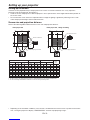
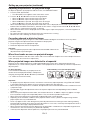
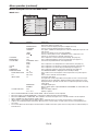
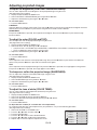
Screen size and projection distance
Refer to the following table to determine the screen size and projection distance.
L
L
W1W1
H1 H2
H
W
L
L
W1W1
H1H2 H
W
Center of the lens
Center of the lens
Maximum projection area Maximum projection area
Front projection Front projection, ceiling mounting
• Depending on the installation conditions, warm air that is emitted from the exhaust vents may fl ow into the intake
vent, causing the projector to display “TEMPERATURE!!” and then stop projecting images.
Screen size Projection distance (L) Lens shift height Lens shift
width
(W1)
Diagonal size Width
(W)
Height
(H)
Shortest
(Wide)
Longest
(Tele)
H1 H2
inch cm inch cm inch cm inch m inch m inch cm inch cm inch cm
40 102 32 81 24 61 54 1.4 74 1.9 12 30 2 6 3 8
60 152 48 122 36 91 82 2.1 112 2.8 18 46 3 9 5 12
80 203 64 163 48 122 110 2.8 150 3.8 24 61 4 11 6 16
100 254 80 203 60 152 138 3.5 189 4.8 30 76 6 14 8 20
150 381 120 305 90 229 208 5.3 284 7.2 45 114 8 21 12 30
200 508 160 406 120 305 279 7.1 380 9.7 60 152 11 28 16 41
250 635 200 508 150 381 349 8.9 - - 75 191 14 36 20 51
300 762 240 610 180 457 419 10.6 - - 90 229 17 43 24 61
• The above fi gures are approximate and may be slightly different from the actual measurements.
• The lens shift height and width show distances from the factory default position.

EN-11
Setting up your projector (continued)
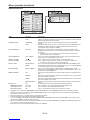
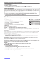
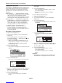
Adjusting the position of the projected image
To adjust the positions of the projector and the screen, use LENS SHIFT button.
1. Press the LENS SHIFT button.
• The LENS SHIFT menu appears at the center of the screen.
2. Press the S, T, W or X button to move the image position.
• When the T button is pressed, the image moves down.
• When the S button is pressed, the image moves up.
• When the X button is pressed, the image moves to the right.
• When the W button is pressed, the image moves to the left.
• When the ENTER button is pressed while the LENS SHIFT menu is displayed, the shift mode can be switched
between FAST and STEP. When FAST is selected, the lens shifts in a large amount with the S, T, W or X button,
and it shifts in a small amount when STEP is selected.
• When the LENS SHIFT menu is displayed while no video signal is input to the projector, a crosshatch appears on
the entire screen.
• Be careful not to be caught in the opening in the lens while the lens is moving.
• While the lens shift is working, the screen may fl icker.
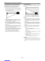
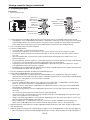
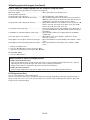
Correcting skewed or distorted image
For the best projection, project images on a fl at screen installed at 90 degrees to the fl oor. If necessary, tilt the
projector using the two adjustment feet on the bottom of the projector.
1. Tilt up the projector to the appropriate angle.
2. Rotate the adjustment feet for fi ne adjustment.
Important:
• Don’t transport the projector with its adjustment feet extended. Otherwise the
adjustment feet may be damaged.
When fi ne streaks are seen on projected images
This is due to interference with the screen surface and is not a malfunction. Replace the screen or displace the focus
a little. (See page 16 or 22 for focus adjustment.)
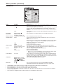
When projected images are distorted to a trapezoid
When the screen and the projector are not placed perpendicularly to each other, projected images become
trapezoidal. If you cannot make the projector and the screen perpendicular to each other by mechanical adjustments,
adjust keystone.
To adjust keystone:
Press the KEYSTONE button on the projector or the
remote control to display KEYSTONE, and adjust the
image by pressing the X, W, S or T button (or VOLUME
+ or - button on the remote control).
LENS
SHIFT
FAST
SELECT:ENTER
Adjustment feet
Screen
In the following cases (for front projection):
Press the T
(or -) button. Press the S
(or +) button.
Press the X
button. Press the W
button.
Important:
• For proper keystone adjustment results, reset the lens to the factory-adjusted position using LENS SHIFT RESET
in the INSTALLATION menu before carrying out keystone adjustment. (See page 30.)
• When the keystone adjustment is carried out, the adjustment value is indicated. Note that this value doesn’t mean
a projection angle.
• The allowable range of the adjustment value in the keystone adjustment varies depending on the installation
conditions.
• When the keystone adjustment takes effect, the resolution decreases. In addition, stripes may appear or straight
lines may bend in images with complicated patterns. They are not due to product malfunctions.
• When the keystone adjustment is performed, the displayed image may be distorted.
• Depending on the installation conditions of the projector and the screen, a perfect rectangular image and the
proper aspect ratio may not be obtained.
• Noise may appear on the screen during the keystone adjustment because of the type of the video signal being
projected and the setting values of the keystone adjustment. In such cases, set the keystone adjustment values in
the range where the image is displayed without noise.
• When horizontal and vertical keystone adjustments are performed in combination, the adjustable range becomes
narrower than in the case when they are performed separately.
• In the keystone adjustment with the option lens, the proper aspect ratio may not be obtained.

EN-12
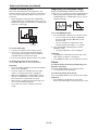
Setting up your projector (continued)
Front projection, ceiling mounting
For ceiling mounting, you need the ceiling mount
kit designed for this projector. Ask a specialist for
installation. For details, consult your dealer.
• The warranty on this projector does not cover any
damage caused by use of any non-recommended
ceiling mount kit or installation of the ceiling mount
kit in an improper location.
• When using the projector mounted on the ceiling,
set IMAGE REVERSE in the INSTALLATION menu
to MIRROR INVERT. See page 30.
• When the projector is mounted on the ceiling,
images may appear darker than those projected in
the case of tabletop mounting. This isn’t a product
malfunction.
• Ask your installation specialist to provide a breaker.
When you do not use the projector, be sure to shut
down the main power by the breaker.
• Do not install the projector where the exhaust vents
are exposed to air emitted by an air conditioning.
Such installation may cause a breakdown.
• Do not install the projector near a fi re alarm
because it emits hot air from its exhaust vents.
Rear projection
Ask a specialist for installation. For details, consult
your dealer.
• For rear projection, set IMAGE REVERSE in the
INSTALLATION menu to MIRROR. See page 30.
Caution:
• Placing the projector directly on a carpet impairs
ventilation by the fans, causing damage or failure.
Put a hard board under the projector to facilitate
ventilation.
• Place the projector at least 50 cm (or 20 inches)
away from the wall to prevent the air inlet grille and
the air outlet grilles that emit hot air from being
blocked.
• Do not use the projector in the following locations
and manners, which may cause fi re or electric
shock.
• In a dusty or humid place.
• In a sideways position, or with the lens facing
down.
• Near a heater.
• In an oily, smoky, or damp place such as a kitchen.
• In direct sunlight.
• Where the temperature rises high, such as in a
closed car.
• Where the temperature is lower than +41ºF (or
+5ºC) or higher than +95ºF (or +35ºC).
Important:
• We don’t recommend using the projector at an
altitude of 1500 meters or higher. Use at an altitude
of 1500 meters or higher may affect the projector’s
life.

EN-13
2
1
Viewing computer images
2
1
AUDIO OUT
AUDIO IN-1/2
2
1
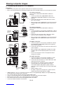
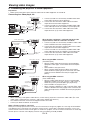
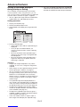
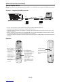
A. Connecting the projector to a computer
Preparation:
• Make sure that the power of the projector and that of the computer are turned off.
• When connecting the projector to a desktop computer, disconnect the RGB cable that is connected to the monitor.
For analog connection:
(For using the COMPUTER/COMPONENT VIDEO IN-1
terminal.)
1. Connect one end of the supplied RGB cable to the
COMPUTER/COMPONENT VIDEO IN-1 terminal of the
projector.
2. Connect the other end of the RGB cable to the monitor
port of the computer.
• When viewing images supplied from an analog-connected
computer, press the COMPUTER 1 button on the remote
control.
For analog connection:
(For using the COMPUTER/COMPONENT VIDEO IN-2
terminal.)
1. Connect one end of a commercially available BNC cable to
the COMPUTER/COMPONENT VIDEO IN-2 terminal of the
projector.
2. Connect the other end of the BNC cable to the 5 BNC
terminals of the monitor port of the computer.
• When viewing images supplied from an analog-connected
computer, press the COMPUTER 2 button on the remote
control.
For digital connection:
1. Connect one end of a commercially available DVI cable to
the COMPUTER/COMPONENT VIDEO DVI-D IN (HDCP)
terminal of the projector.
2. Connect the other end of the DVI cable to the DVI terminal
of the computer.
• When viewing images supplied from a digital-connected
computer, press the DVI-D(HDCP) button on the remote
control.
• Turn on the main power switch of the projector before
starting the computer.
For audio connection:
1. Connect one end of a commercially available PC audio
cable to the AUDIO IN-1/2 terminal of the projector.
2. Connect the other end of the PC audio cable to the audio
output terminal of the computer.
• This projector uses stereo pin jack for its audio input.
Check the type of the audio output terminal of the
connected computer and prepare a proper cable for
connection. Some computers don’t have the audio output
terminal.
• Speaker output is mono.
• No audio is output from the projector’s speaker and the
AUDIO OUT terminal during power standby.
COMPUTER/
COMPONENT
VIDEO IN-1
COMPUTER/
COMPONENT
VIDEO DVI-D IN
(HDCP)
To monitor port
RGB cable
DVI cable (option)
To DVI
Computer
PC audio cable
(option) To audio output
terminal
2
1
R/PRG/Y B/PBH/HV V
V H/HV B/PBG/Y R/PR
COMPUTER/
COMPONENT
VIDEO IN-2
• Additional devices, such as a conversion connector and an analog RGB output adapter, are required depending
on the type of the computer to be connected.
• Use of a long cable may decrease the quality of projected images.
• Images may not be projected correctly, depending on the type of the connected computer.
• When DVI-D signal is input, some signal setting menus are unavailable.
• Also read the instruction manual of the equipment to be connected.
• Contact your dealer for details of connection.
To monitor
port (5 BNC)
Computer
Computer
Computer
BNC cable (option)

EN-14
Viewing computer images (continued)
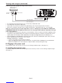
1. Plug the attached power cord into the power cord inlet of
this projector.
2. Plug the other end of the power cord into a power outlet.
• One of power cords for the U.S., Europe and U.K. is provided appropriately.
• This projector uses the power plug of 3-pin grounding type. Do not remove the grounding pin from the power
plug. If the power plug doesn’t fi t your wall outlet, ask an electrician to change the wall outlet.
• In case that the power cord for the U.S. is provided with this projector, never connect this cord to any outlet
or power supply using other voltages or frequencies than rated. If you want to use a power supply using other
voltage than rated, prepare an appropriate power cord separately.
• Use 100-240 V AC 50/60 Hz to prevent fi re or electric shock.
• Do not place any objects on the power cord or do not place the projector near heat sources to prevent damage to
the power cord. If the power cord should be damaged, contact your dealer for replacement because it may cause
fi re or electric shock.
• Do not modify or alter the power cord. If the power cord is modifi ed or altered, it may cause fi re or electric shock.
Caution:
• Plug in the power cord fi rmly. When unplugging, hold and pull the power plug, not the power cord.
• Do not plug in or out the power cord with your hand wet. It may cause electric shock.
2
1
Earthing
terminal
Power cord (example)
About DDC
The COMPUTER/COMPONENT VIDEO IN-1 terminal of this projector complies with the DDC1/2B standard and the
COMPUTER/COMPONENT VIDEO DVI-D IN (HDCP) terminal complies with the DDC2B standard. When a computer
supporting this standard is connected to this terminal, the computer will automatically load the information from this
projector and prepare for output of appropriate images.
• When connecting a DDC-supporting computer to the projector, turn on the main power switch of the projector
before starting the computer.
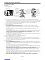
1
Monitor
For monitor connection:
1. Connect the RGB cable from the monitor to the MONITOR
OUT terminal of the projector.
• No video signal is output from the MONITOR OUT terminal
during power standby.
For audio output connection:
1. Connect one end of a commercially available audio cable
to the AUDIO OUT terminal of the projector.
2. Connect the other end (white and red) of the audio cable to
the audio input terminals (L, R) of the audio equipment.
• When the audio cable is connected to the AUDIO OUT
terminal, the speaker output is muted.
AUDIO OUT 2
1
Audio cable (option)
To audio input
terminals
MONITOR OUT
RGB cable
B. Plugging the power cord
• In order to ensure the safety in case of trouble with the projector, use an electrical outlet having an earth leakage
breaker to supply the power to the projector. If you do not have such outlet, ask your dealer to install it.

EN-15
C. Installing the terminal cover
This projector includes a terminal cover. If necessary, install the terminal cover to the projector.
1. Fit two hooks of the terminal cover into the projector.
2. Tighten the attachment screws (a) fi rmly.
Important:
• Don’t carry the projector by the terminal cover.
(a)
Viewing computer images (continued)

EN-16
Viewing computer images (continued)
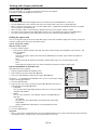
D. Projecting images
Preparation:
• Remove the lens cap.
POWER button
COMPUTER/
DVI-D button
COMPUTER 1, 2 buttons
LENS SHIFT button
POWER button
ZOOM/FOCUS button
LENS SHIFT button
Main power switch
ZOOM/FOCUS button
DVI-D(HDCP)
button
POWER indicator
STATUS indicator
ENTER button
S, T, W, X buttons
ENTER button
S, T, W, X
buttons
1. Put the projector into standby mode by pressing the main power switch. The POWER indicator lights up red.
• If the projector was turned off before the lamp was cooled down suffi ciently last time, the fan may start rotating
and the POWER button may not work after the main power switch is turned ON. (The STATUS indicator blinks
green.) After the fan stops rotating, press the POWER button to turn back on the POWER indicator.
2. Turn on the power of the connected computer.
3. Press the POWER button.
• It may take about 1 minute for the lamp to light up.
• The lamp fails to light up on rare occasions. In such a case, wait for a few minutes and then try again.
• Do not cover the lens with the lens cap while the lamp is on. Do not strip off the aluminium sheet inside the
lens cap.
• After the POWER button is pressed, the image may fl icker before the lamp becomes stable. This is not a
product malfunction.
• The lamp operation becomes stable in 1 minute after the power is turned on and then the lamp mode selected
in the menu is activated. During the activation, displayed images may be disturbed.
• The projector starts warming up when the POWER button is pressed. During the warm-up process, images
may appear dark and no commands are accepted.
• By blinking red, the STATUS indicator indicates that the lamp should be replaced soon. Replace the lamp when
the STATUS indicator blinks red. (See page 42.)
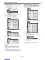
4. Press the ZOOM/FOCUS button to display the ZOOM/FOCUS menu.
5. Adjust with the W or X button to get a fi ne picture.
• When the ENTER button is pressed while the ZOOM/FOCUS menu is displayed, the adjustment mode is
switched between FAST and STEP. When FAST is selected, the speed of focus controlled by the W or X button
becomes fast, and it becomes slow when STEP is selected.
6. Select an input source.
• Press the COMPUTER/DVI-D button on the projector or the COMPUTER 1, COMPUTER 2 or DVI-D(HDCP)
button on the remote control that is corresponding to the terminal in use.
• The input source is switched from COMPUTER 1 to COMPUTER 2 to DVI at every press of the COMPUTER/
DVI-D button on the projector.
• The projector automatically selects the appropriate signal format. The selected signal format is displayed on
the screen.
• You cannot change the input source while the menu is being displayed.
• Though it may take some time before an image is displayed on the screen depending on the type of the input
signal, such symptom is not a malfunction.
• Images may not be projected in the correct position, depending on the type of the input signal. In such a case,
press the AUTO POSITION button. (See page 18.)
• When COMPUTER 1 or COMPUTER 2 is chosen as the source, images supplied from the computer may
fl icker. Press the W or X button on the remote control to reduce fl icker, if it occurs. (Fine adjustment)
7. Adjust the position of the projector to keep an appropriate projection distance with which images are projected in
their specifi ed sizes.
8.
Adjust the position of the projector so that the projector and the screen are perpendicular to each other. (See page 10.)
•
When the projector cannot be positioned perpendicularly to the screen, adjust the projection angle. (See page 11.)

EN-17
Viewing computer images (continued)
9. Press the ZOOM/FOCUS button to display the ZOOM/FOCUS menu.
10. Adjust with the S or T button to get an approximate size.
• When the ENTER button is pressed while the ZOOM/FOCUS menu is displayed, the adjustment mode is
switched between FAST and STEP. When FAST is selected, the speed of zoom controlled by the S or T
button becomes fast, and it becomes slow when STEP is selected.
11. Press the LENS SHIFT button. The LENS SHIFT menu appears at the center of the screen.
12.Press the S or T button to adjust the vertical position and W or X button to adjust the horizontal position of the
displayed image.
• When the image is not displayed within the screen, adjust the projection angle. In addition, perform the
keystone adjustment, if necessary. (See page 11.)
Repeat steps 4, 5 and 9 to 12, if necessary.
Important:
• Focus, zoom and lens shift adjustment is possible in the normal picture mode only.
• When a 16:9 image is kept displayed for a long time before displaying 4:3 image, the afterimages of the black bars
may appear on the 4:3 image screen. Consult your dealer in this case.
To stop projecting:
13. Press the POWER button.
• A confi rmation message is displayed.
• To cancel the procedure, leave the projector for a while or press any button except the POWER button.
14. Press the POWER button again.
• The lamp goes out and the projector goes into a standby mode. In this standby mode, the STATUS indicator
blinks green.
15. Wait about 2 minutes for the STATUS indicator to be turned off.
• During this period of 2 minutes in the standby mode, the intake fan and exhaust fan rotate to cool the lamp.
• The air outlet fans rotate faster as the temperature around the projector rises.
• Though the fans make loud sounds during cooling, such symptom is not a malfunction.
16. Turn off the main power switch.
• The POWER indicator will go out.
• If the main power switch should be turned off or the power cord should be unplugged accidentally while either
the air inlet fan or the air outlet fans are operating or the lamp is on, allow the projector to cool down for 10
minutes with the power off. To light the lamp again, press the POWER button. If the lamp doesn’t light up
immediately, repeat pressing the POWER button 2 or 3 times. If it should still fail to light up, replace the lamp.
• Cover the lens with the lens cap to protect it from dust.
• For safety’s sake, unplug the power cord from the outlet.
• When you repeat turning off the main switch within 30 minutes from the lamp illumination, an error may occur
in the clock function of this product.
Direct Power OFF
You can turn off this projector just by turning off the power switch or unplugging the power cord without pressing the
POWER button.
• Don’t shut down the projector while the STATUS indicator is blinking after the lamp lights up because the lamp’s
life may be shortened.
• Don’t turn the projector back on right after shutting it down because the lamp's life may be shortened. (Wait about
10 minutes before turning the projector back on.)
• Before shutting down the projector, be sure to close the menu screen. If you shut down the projector without
closing the menu, the setting data of the menu may not be saved.
• If you shut down the projector while controlling the projector using the network function, the application software
such as ProjectorView may fail. For details, see “User Guide of LAN Control Utility” contained in the CD-ROM.

EN-18
AV mute
The video and audio signals are temporarily muted when the AV MUTE button is pressed. To cancel muting, press the
AV MUTE button again.
• It takes several seconds before muting is completely canceled.
• If AV MUTE MODE in the INSTALLATION menu is set to IMAGE, the splash screen will appear when the AV MUTE
button is pressed.
• You can alter the splash screen optionally. See page 37.
• The audio from the AUDIO OUT terminal is also muted by pressing the AV MUTE button.
AUTO POSITION button
When the image supplied from the computer is displaced, carry out the following procedure.
1. Project a bright image containing as many texts and characters as possible.
2. When the screen saver has been enabled, disable it.
3. Press the AUTO POSITION button.
The projector automatically makes optimum positional settings for the input signal.
• If the projected image is still displaced even after pressing the AUTO POSITION button several times, refer to
the procedure to adjust computer images. (See pages 35 and 36.)
• When you carry out this procedure with a dark image, the image may be displaced.
When connecting to a notebook computer:
When the projector is connected to a notebook computer, images may not be projected in some cases. In such
cases, set the computer so that it can output signals externally. The setting procedure varies depending on the type
of the computer. See the instruction manual of your computer.
Example of the setting procedure for external output
Press the [Fn] key and any of the keys [F1] to [F12] at the same time. (The key to be pressed depends on the type of
the computer you use.)
Setting of the resolution
If the resolution of the computer doesn’t match with that of the projector, projected images may be obscured. Ensure
that their resolutions are the same (see page 51). For the method to change the output resolution of the computer,
contact the manufacturer of the computer.
Viewing computer images (continued)

EN-19
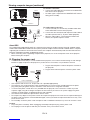
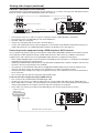
Viewing video images
Connecting to a video player, etc.
1. Connect one end of a commercially available video cable
to the VIDEO IN terminal of the projector.
2. Connect the other end of the video cable to the video
output terminal of the video equipment.
3. Connect one end of a commercially available audio cable
to the audio input terminals (L/MONO, R) of the projector.
4. Connect the other end of the audio cable to the audio
output terminals (L, R) of the video equipment.
When the video equipment is equipped with the S-video
output terminal, make the connection as follows:
1. Connect one end of a commercially available S-video cable
to the S-VIDEO IN terminal of the projector.
2. Connect the other end of the S-video cable to the S-video
output terminal of the video equipment.
3. Connect one end of a commercially available audio cable
to the audio input terminals (L/MONO, R) of the projector.
4. Connect the other end of the audio cable to the audio
output terminals (L, R) of the video equipment.
When using the BNC connector:
(For VIDEO input)
• When the video output terminal of the connected video
equipment is BNC type, use the VIDEO IN terminal (BNC
type).
• Select VIDEO as the input source.
• When using the VIDEO IN terminal (BNC type) and the
VIDEO IN terminal (RCA type) at the same time, the video
signal input to the VIDEO IN terminal (RCA type) takes
priority.
When using the BNC connector:
(For S-VIDEO input)
• When the video output terminals of the connected video
equipment are BNC (Y/C) type, connect Y and C to the S-
VIDEO IN (Y and C) terminals (BNC type) respectively.
• Select S-VIDEO as the input source.
• When using the S-VIDEO IN (Y and C) terminals (BNC type)
and the S-VIDEO IN terminal (S type) at the same time, the
video signal input to the S-VIDEO IN terminal (S type) takes
priority.
• When connecting a monophonic video device, use the white (L) terminal to connect the audio cable. (The same
audio signal is output from the channels L and R of the AUDIO OUT terminal.)
• Also read the instruction manual of the equipment to be connected.
• Contact your dealer for details of connection.
When a TV tuner or VCR is connected:
When you use this projector with a TV tuner or VCR connected, no image may appear or a message of “NO SIGNAL”
may appear on the screen when you change the channel via any channel that is not being received. In such a case,
set the channels of the TV tuner or VCR again. To avoid such symptom, use the TV tuner or VCR with its channel skip
function (that is a function not to display channels that are not being received) enabled.
A. Connecting the projector to video equipment
Preparation:
• Make sure that the power of the projector and that of the video equipment are turned off.
3
4
12
14
2
3
To VIDEO
IN terminal
To video
output
terminal
Video player, or the like
To S-VIDEO
IN terminal
S-video cable (option)
To S-video
output
terminal
Video player, or the like
Audio cable
(option)
To audio
input
terminals
To audio
output
terminals
To audio
input
terminals Audio cable
(option)
To audio
output
terminals
To VIDEO
IN terminal
(BNC)
BNC cable (option)
To video
output
terminal
Video player, or the like
To S-VIDEO IN
(Y and C) terminals
(BNC)
BNC cable (option)
To S-video (Y/C)
output terminals
Video player, or the like
Video cable
(option)

EN-20
Viewing video images (continued)
Projector + DVD player or HDTV decoder
Some DVD players have an output connector for 3-line fi tting (Y, CB, CR). When connecting such DVD player with this
projector, use the COMPUTER/COMPONENT VIDEO IN-2 terminals.
CB(PB)Y CR(PR)
B G R
AUDIO IN-2
BNC cable (option)
DVD player or HDTV decoder
BNC-RCA connector (option)
COMPUTER/COMPONENT
VIDEO IN-2
Audio cable (option)
To audio output terminals
• The terminal’s names Y, PB, and PR are given as examples of when a HDTV decoder is connected.
• The terminal’s names vary depending on the connected devices.
• Use BNC cables for connection.
• Image may not be projected correctly with some DVD players.
• If colors aren’t displayed correctly when the projector is connected to a high-defi nition video device having R, G,
and B output terminals, set COMPUTER INPUT to RGB in the SIGNAL menu. (See page 32.)
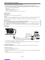
Connecting to video equipment having a HDMI terminal or DVI-D terminal
You can project high-quality images by connecting the COMPUTER/COMPONENT VIDEO DVI-D IN (HDCP) terminal
of this projector to video equipment having a HDMI output terminal or DVI-D terminal. In addition, this projector
supports HDCP and is able to receive encrypted digital video data that are output from DVD players.
• HDCP (High-bandwidth Digital Content Protection), developed by Intel Corporation, is a method to encrypt digital
video data for the purpose of copy protection.
• HDMI (High-Defi nition Multimedia Interface) is fully backward compatible with computers, displays and consumer
electronics devices incorporating the DVI standards.
• This projector can be linked with video devices equipped with HDMI output terminal or DVI-D output terminal.
However, with some of them, this projector may not display any image or not operate correctly.
• If this projector doesn’t display any image or not operate correctly, see the operation manual of the video device
for its connection.
• Use of a long cable may decrease the quality of projected images.
Connection (for video equipment having an HDMI terminal)
• Use a commercially available HDMI (with HDMI logo) cable.
• You don’t have to connect any cable for audio input. You can input video and audio using an HDMI cable only.
• When HDMI audio isn’t output, it may be output by turning off the power of the video equipment with the projector
and the video equipment connected to each other and then turning back on the power.
• Some cables may not be connected correctly depending on the size and shape of their connectors.
Equipment having an
HDMI terminal
To HDMI terminal
HDMI IN
HDMI (with HDMI logo) cable (option)
Page is loading ...
Page is loading ...
Page is loading ...
Page is loading ...
Page is loading ...
Page is loading ...
Page is loading ...
Page is loading ...
Page is loading ...
Page is loading ...
Page is loading ...
Page is loading ...
Page is loading ...
Page is loading ...
Page is loading ...
Page is loading ...
Page is loading ...
Page is loading ...
Page is loading ...
Page is loading ...
Page is loading ...
Page is loading ...
Page is loading ...
Page is loading ...
Page is loading ...
Page is loading ...
Page is loading ...
Page is loading ...
Page is loading ...
Page is loading ...
Page is loading ...
Page is loading ...
Page is loading ...
-
 1
1
-
 2
2
-
 3
3
-
 4
4
-
 5
5
-
 6
6
-
 7
7
-
 8
8
-
 9
9
-
 10
10
-
 11
11
-
 12
12
-
 13
13
-
 14
14
-
 15
15
-
 16
16
-
 17
17
-
 18
18
-
 19
19
-
 20
20
-
 21
21
-
 22
22
-
 23
23
-
 24
24
-
 25
25
-
 26
26
-
 27
27
-
 28
28
-
 29
29
-
 30
30
-
 31
31
-
 32
32
-
 33
33
-
 34
34
-
 35
35
-
 36
36
-
 37
37
-
 38
38
-
 39
39
-
 40
40
-
 41
41
-
 42
42
-
 43
43
-
 44
44
-
 45
45
-
 46
46
-
 47
47
-
 48
48
-
 49
49
-
 50
50
-
 51
51
-
 52
52
-
 53
53


Mitsubishi Electric XD3500U User manual
- Category
- Data projectors
- Type
- User manual
- This manual is also suitable for
Ask a question and I''ll find the answer in the document
Finding information in a document is now easier with AI
Related papers
-
Mitsubishi XL6500LU User manual
-
Mitsubishi FL6900 User manual
-
Mitsubishi Electric XD2000 User manual
-
Mitsubishi WL7050U User manual
-
Mitsubishi UL7400U User manual
-
Mitsubishi XL7100U User manual
-
Mitsubishi HC7800D User manual
-
Mitsubishi HL2750U User manual
-
-
Other documents
-
Eiki LC-WIP3000 User manual
-
-
-
-
 Saville PowerLite PX-3100L User manual
-
-
Hitachi CP-X705 User manual
-
Hitachi Projector CP-X809 User manual
-
Mitsubishi HC1500 User manual
-
