
GS-R12PE
GS-R12PE1
Dual LGA2011 socket motherboard for Intel® Xeon® series processors
Service Guide
Rev. 1.0

Copyright
© 2012 GIGA-BYTE TECHNOLOGY CO., LTD. All rights reserved.
The trademarks mentioned in this manual are legally registered to their respective owners.
Disclaimer
Information in this manual is protected by copyright laws and is the property of GIGABYTE.
Changes to the specifications and features in this manual may be made by GIGABYTE
without prior notice. No part of this manual may be reproduced, copied, translated, transmitted, or
published in any form or by any means without GIGABYTE's prior written permission.
Documentation Classications
In order to assist in the use of this product, GIGABYTE provides the following types of documentations:
For detailed product information, carefully read the Serice Guide.
For product-related information, check on our website at:
http://www.gigabyte.com

Preface
Before using this information and the product it supports, please read the following general infor-
mation.
1. This Service Guide provides you with all technical information relating to the BASIC CON-
FIGURATION decided for GIGABYTE’s “global” product offering. To better t local market-
requirements and enhance product competitiveness, your regional ofce MAY have decided
toextend the functionality of a machine (e.g. add-on card, modem, or extra memory capabil-
ity).These LOCALIZED FEATURES will NOT be covered in this generic service guide. In
suchcases, please contact your regional ofces or the responsible personnel/channel to
provide youwith further technical details.
2. Please note WHEN ORDERING SPARE PARTS, you should check the most up-to-date
informationavailable on your regional web or channel. For whatever reason, if a part num-
ber change is made,it will not be noted in the printed Service Guide. For GIGABYTE-AU-
THORIZED SERVICEPROVIDERS, your GIGABYTE ofce may have a DIFFERENT part
number code to thosegiven in the FRU list of this printed Service Guide. You MUST use the
list provided by yourregional GIGABYTE ofce to order FRU parts for repair and service of
customer machines.

- 4 -
Table of Contents
Box Contents ...................................................................................................................6
Safety, Care and Regulatory Information ........................................................................7
Chapter 1 Hardware Installation ...................................................................................10
1-1 Installation Precautions .................................................................................. 10
1-2 Product Specications .................................................................................... 11
Chapter 2 System Hardware Installation ......................................................................13
2-1 Removing System Cover ............................................................................... 14
2-2 Removing and Installing the Fan Duct ........................................................... 15
2-3 Installing the CPU ......................................................................................... 16
2-4 Installing the Heat Sink ................................................................................. 17
2-5 Installing the Memory ..................................................................................... 18
2-5-1 Four Channel Memory Conguration .....................................................................18
2-4-2 Installing a Memory ...............................................................................................19
2-4-3 DIMM Population Table .........................................................................................20
2-6 Installing the PCI Expansion Card ................................................................. 21
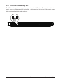
2-7 Installing the Hard Disk Drive ........................................................................ 22
2-7-1 Hard Disk Drive Security Lock ................................................................................23
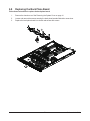
2-8 Replacing the Back Plane Board ................................................................... 24
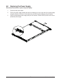
2-9 Replacing the Power Supply .......................................................................... 25
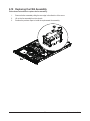
2-10 Replacing the FAN Assemblly ........................................................................ 26
Chapter 3 System Appearance .....................................................................................27
3-1 Front View ..................................................................................................... 27
3-2 Rear View ....................................................................................................... 28
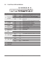
3-3 Front Panel LED and Buttons ........................................................................ 29
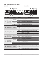
3-4 Rear System LAN LEDs ................................................................................. 30
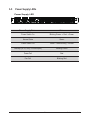
3-5 Power Supply LEDs ....................................................................................... 31
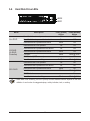
3-6 Hard Disk Drive LEDs .................................................................................... 32
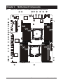
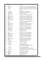
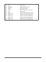
Chapter 4 Motherboard Components ...........................................................................33
4-1 GA-7PPSH/GA-7PPSH2 Motherboard Components ..................................... 33
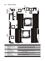
4-2 Jumper Setting ............................................................................................... 36
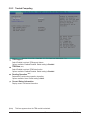
Chapter 5 BIOS Setup ..................................................................................................38
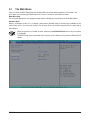
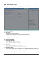
5-1 The Main Menu .............................................................................................. 40

- 5 -
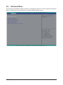
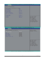
5-2 Advanced Menu ............................................................................................. 42
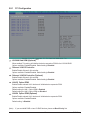
5-2-1 PCI Conguration ...................................................................................................43
5-2-2 Trusted Computing .................................................................................................45
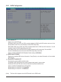
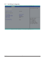
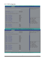
5-2-3 CPU Conguration ..................................................................................................46
5-2-4 Runtime Error Logging ...........................................................................................50
5-2-5 SATA Conguration.................................................................................................51
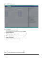
5-2-6 SAS Conguration ..................................................................................................52
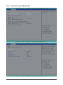
5-2-6 Serial Port Console Redirection .............................................................................53
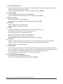
5-3 Chipset Menu ................................................................................................. 55
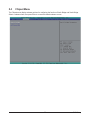
5-3-1 North Bridge Conguration .....................................................................................56
5-3-1-1 IOH Conguration ...................................................................................................57
5-3-1-2 DIMM Information ...................................................................................................60
5-3-2 South Bridge Conguration ....................................................................................62
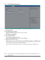
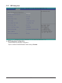
5-3-3 ME Subsystem .......................................................................................................63
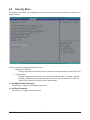
5-4 Security Menu ................................................................................................ 64
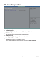
5-5 Server Management Menu ............................................................................. 65
5-5-1 System Information .................................................................................................66
5-5-2 BMC LAN Conguration .........................................................................................67
5-5-3 System Event Log ..................................................................................................68
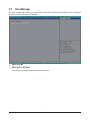
5-6 Boot Option Menu .......................................................................................... 69
5-7 Boot Manager ................................................................................................. 70
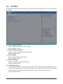
5-8 Exit Menu ....................................................................................................... 71
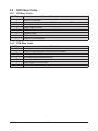
5-9 BIOS Beep Codes .......................................................................................... 72
5-9-1 PEI Beep Codes .....................................................................................................72
5-9-2 DXE Beep Codes ...................................................................................................72
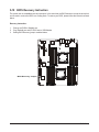
5-10 BIOS Recovery Instruction ............................................................................. 73

- 6 -
Box Contents
GS-R12PE/GS-R12PE1
Driver CD
• The box contents above are for reference only and the actual items shall depend on the product package you obtain.
The box contents are subject to change without notice.
• The motherboard image is for reference only.

- 7 -
Safety, Care and Regulatory Information
Important safety information
Read and follow all instructions marked on the product and in the documentation before you operateyour sys-
tem. Retain all safety and operating instructions for future use.
• The product should be operated only from the type of power source indicated on the rating label.* If your
computer has a voltage selector switch, make sure that the switch is in the proper position foryour area.
The voltage selector switch is set at the factory to the correct voltage.
• The plug-socket combination must be accessible at all times because it serves as the main disconnect-
ing device.
• All product shipped with a three-wire electrical grounding-type plug only fits into a grounding-type
poweroutlet. This is a safety feature. The equipment grounding should be in accordance with local and
nationalelectrical codes. The equipment operates safely when it is used in accordance with its marked
electricalratings and product usage instructions
• Do not use this product near water or a heat source.* Set up the product on a stable work surface or so
as to ensure stability of the system.
• Openings in the case are provided for ventilation. Do not block or cover these openings. Make sure
youprovide adequate space around the system for ventilation when you set up your work area. Never
insertobjects of any kind into the ventilation openings.
• To avoid electrical shock, always unplug all power cables and modem cables from the wall outletsbefore
removing covers.
• Allow the product to cool before removing covers or touching internal components.
Precaution for Product with Laser Devices
Observe the following precautions for laser devices:
• Do not open the CD-ROM drive, make adjustments, or perform procedures on a laser device other than
those specied in the product's documentation.
• Only authorized service technicians should repair laser devices.
Precaution for Product with Modems, Telecommunications, ot Local AreaNetwork Options
Observe the following precautions for laser devices:
• Do not connect or use a modem or telephone during a lightning storm. There may be a risk of electri-
calshock from lightning.
• To reduce the risk of re, use only No. 26 AWG or larger telecommunications line cord.
• Do not plug a modem or telephone cable into the network interface controller (NIC) receptacle.
• Disconnect the modem cable before opening a product enclosure, touching or installing internalcompo-
nents, or touching an uninsulated modem cable or jack.
• Do not use a telephone line to report a gas leak while you are in the vicinity of the leak.

- 8 -
Federal Communications Commission (FCC) Statement
Warning
This is a class A product. In a domestic environment this product may cause radiointerfer-
enceIn which case the user may be required to take adequate measures.
This equipment has been tested and found to comply with the limits for a Class A digital device,pursuant to
Part 15 of the FCC Rules. These limits are designed to provide reasonable protection againstharmful interfer-
ence when the equipment is operated in a commercial environment. This equipmentgenerates, uses, and can
radiate radio frequency energy and, if not installed and used in accordance withthe instruction manual, may
cause harmful interference to radio communications. Operation of thisequipment in a residential area is likely
to cause harmful interference in which case the user will berequired to correct the interference at his own ex-
pense.Properly shielded and grounded cables and connectors must be used in order to meet FCC emission-
limits. Neither the provider nor the manufacturer are responsible for any radio or television interferencecaused
by using other than recommended cables and connectors or by unauthorized changes ormodications to this
equipment. Unauthorized changes or modications could void the user's authority tooperate the equipment.
This device complies with Part 15 of the FCC Rules. Operation is subject to the following two conditions:
(1) this device may not cause harmful interference, and
(2) this device must accept any interference received, including interference that may cause undesired opera-
tion.
Canadian Department of Communications Compliance Statement
This digital apparatus does not exceed the Class A limits for radio noise emissions from digitalapparatus as
set out in the radio interference regulations of Industry Canada.Le present appareil numerique n'emet pas
de bruits radioelectriques depassant les limites applicables auxappareils numeriques de Classe A prescrites
dans le reglement sur le brouillage radioelectrique edicte parIndustrie Canada.
Class A equipment
This device has been tested and found to comply with the limits for a class A digital device pursuant Part 15
of the FCC Rules. These limits are designed to provide reasonable protection againstharmful interference
when the equipment is operated in a commercial environment. This equipmentgenerate, uses, and can radi-
ate radio frequency energy, and if not installed and used in accordancewith the instructions, may cause harm-
ful interference to radio communication. Operation of thisequipment in a residential area is likely to cause
harmful interference, in which case the user will berequired to correct the interference at personal expence.
However, there is no guarantee that interference will not occur in a particular installation. If thisdevice does
cause harmful interference to radio or television reception, which can be determined bytuning the device off
and on, the user is encouraged to try to correct the interference by on or more ofthe following measures:
• Reorient or relocate the receiving antenna
• Increase the separation between the device and receiver
• Connect the device into an outlet on a circuit different from that to which the receiver isconnected'Consult
the dealer or an experienced radio/television technician for help.

- 9 -
Battery Warning: Incorrectly installing a battery or using incompatible battery may increase
the risk of ifre explosion. Replace the battery only with the same or equivalent type.
• Do not disassemble, crush, punchture batteries.
• Do not store or place your battery pack next to or in a heat source such as a re, heatgenerating
appliance, can or exhaust vent. Heating battery cells to temperatures above 65oC (149oF) can
cause explosion or re.
• Do not attempt to open or service batteries. Do not dispose of batteries in a re or with house-
hold waste.
WEEE Symbol Statement
The symbol shown below is on the product or on its packaging, which indicates that this product
must not be disposed of with other waste. Instead, the device should be taken to the waste
collection centers for activation of the treatment, collection, recycling and disposal procedure.
The separate collection and recycling of your waste equipment at the time of disposal will help to
conserve natural resources and ensure that it is recycled in a manner that protects human health
and the environment. For more information about where you can drop off your waste equipment for recycling,
please contact your local government ofce, your household waste disposal service or where you purchased
the product for details of environmentally safe recycling.
w When your electrical or electronic equipment is no longer useful to you, "take it back" to your local or
regional waste collection administration for recycling.
w If you need further assistance in recycling, reusing in your "end of life" product, you may contact us at the
Customer Care number listed in your product's user's manual and we will be glad to help you with your
effort.

Hardware Installation - 10 -
1-1 Installation Precautions
The motherboard/system contain numerous delicate electronic circuits and components which
can become damaged as a result of electrostatic discharge (ESD). Prior to installation, carefully
read the service guide and follow these procedures:
• Prior to installation, do not remove or break motherboard S/N (Serial Number) sticker or
warranty sticker provided by your dealer. These stickers are required for warranty validation.
• Always remove the AC power by unplugging the power cord from the power outlet before
installing or removing the motherboard or other hardware components.
• When connecting hardware components to the internal connectors on the motherboard,
make sure they are connected tightly and securely.
• When handling the motherboard, avoid touching any metal leads or connectors.
• It is best to wear an electrostatic discharge (ESD) wrist strap when handling electronic com-
ponents such as a motherboard, CPU or memory. If you do not have an ESD wrist strap,
keep your hands dry and rst touch a metal object to eliminate static electricity.
•
Prior to installing the motherboard, please have it on top of an antistatic pad or within an
electrostatic shielding container.
• Before unplugging the power supply cable from the motherboard, make sure the power sup-
ply has been turned off.
• Before turning on the power, make sure the power supply voltage has been set according to
the local voltage standard.
• Before using the product, please verify that all cables and power connectors of your hard-
ware components are connected.
• To prevent damage to the motherboard, do not allow screws to come in contact with the
motherboard circuit or its components.
• Make sure there are no leftover screws or metal components placed on the motherboard or
within the computer casing.
• Do not place the computer system on an uneven surface
.
• Do not place the computer system in a high-temperature environment.
• Turning on the computer power during the installation process can lead to damage to sys-
tem components as well as physical harm to the user.
• If you are uncertain about any installation steps or have a problem related to the use of the
product, please consult a certied computer technician.
Chapter 1 Hardware Installation

- 11 - Hardware Installation
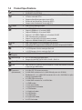
1-2 ProductSpecications
Motherboard wGS-R12PE: GA-7PPSH
wGS-R12PE1: GA-7PPSH2
CPU wSupport for Intel® Xeon® E5-2600 series processors in the LGA2011 package
wL3 cache varies with CPU
wSupports QuickPath Interconnect up to 8GT/s
wEnhanced Intel SpeedStep Technology (EIST)
wSupport Intel Virtualization Technology (VT)
Chipset wIntel® C602 (Patsburg) Chipset
Memory w24 x DDR3 DIMM sockets
wSupport UDIMM up to 16 scokets/128GB
wSupport RDIMM up to 24 sockets/768GB
wSupports 1.35V DDR3L DIMM up to 16 sockets/128 GB
wFour channel memory architecture
wSupport for 800/1066/1333/1600 memory modules
wSupport for RDIMM/UDIMM (ECC) memory modules
LAN wIntel® I350 supports 10/100/1000 Mbps (GS-R12PE1)
wIntel® X540-AT2 supports dual 10G Base-T ethernet LAN ports (GS-R12PE)
Expansion Slot wLow-Prole:
w 1 x PCI Express x16 slot, running at Gen3 x16
w 1 x PCI Express x16 slot, running at Gen3 x8
Onboard
Graphics
wASPEED® AST2300 supports 64MB VRAM
Mass Storage w4 x 3.5” Hot-Swap SATA/SAS HDDs
wSupport for Intel IRST SATA RAID 0, RAID 1, RAID 10
System Fans w6 x 40x40x56mm 16000rpm
USB wUp to 4 USB 2.0/1.1 ports (2 on the back panel, 2 via the USB brackets connected
to the internal USB headers)
Internal
Connectors
(Motherboard)
w1 x 24-pin ATX power connector
w2 x 8-pin ATX 12V power connectors
w2 x Mini-SAS connectors for 8 x SAS 6Gb/s (8 ports via LSI 2008)
wEnablement of 1 or 2 x Mini-SAS connectors for 4 or 8 x SAS 3Gb/s in option
through upgradable ROM
w2 x SATA 6Gb/s connectors
w1 x Mini-SAS connector for 4 x SATA 3Gb/s
w1 x IPMB header
w1 x front panel header
w1 x back plane board header
w1 x TPM headers
w1 x Serial port header
w2 x USB headers
w1 x PSMI header
w2 x System fan header
w2 x CPU fan header

Hardware Installation - 12 -
Internal
Connectors
(Back Plane
Board)
w12 x SATA/SAS 6Gb/s connectors
w2 x 7-pin power connectors
w2 x 4-pin power connectors (For optional inter HDDs)
w1 x back plane board header
w3 x SGPIO connectors
w8 x Systen fan connectors
Rear Panel I/O w2 x USB 2.0/1.1 ports
w4 x RJ-45 ports (GA-R12PE)
w2 x RJ-45 ports (GA-R12PE1)
w1 x Server Management LAN port
w1 x COM port
w1 x VGA port
w1 x ID button/LED
Front Panel
LED/Buttons
w1 x Power button/LED
w1 x ID button/LED
w1 x System status LED
w1 x HDD Status LED
w2 x LAN LEDs
w1 x Reset button
w1 x NMI button
BMC Controller wASPEED® AST2300
Hardware
Monitor
wSystem voltage detection
wCPU/System temperature detection
wCPU/System fan speed detection
wCPU/System fan speed control
* Whether the CPU/system fan speed control function is supported will depend on
the CPU/system cooler you install.
BIOS w1 x 64 Mbit ash
wAMI BIOS
Environment
Ambient
Temperature
Relative
Humidity
wOperating Temperature: 5oC to 35oC
wNon-operating Temperature: 0oC to 40oC
w10-80% operating Humidity at 30oC
System
Dimension
w429.8Wx43.5Hx709D (mm)
Electrical
Power Supply
wHot-swap 1+1 Redundant 650W 380VDC at 80 plus platnium (GS-R12PE)
wHot-swap 1+1 Redundant 650W 110~220VAC at 80 plus gold (GS-R12PE1)
* GIGABYTE reserves the right to make any changes to the product specications and product-related information
without prior notice.

- 13 - Hardware Installation
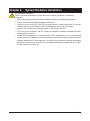
Chapter 2 System Hardware Installation
Pre-installation Instructions
Perform the steps below before you open the server or before you remove or replaceany
component.
• Back up all important system and data les before performing any hardwareconguration.
• Turn off the system and all the peripherals connected to it.
• Locate the pin one of the CPU. The CPU cannot be inserted if oriented incorrectly. (Or you may
locate the notches on both sides of the CPU and alignment keys on the CPU socket.)
• Apply an even and thin layer of thermal grease on the surface of the CPU.
• Do not turn on the computer if the CPU cooler is not installed, otherwise overheating and dam-
age of the CPU may occur.
• Set the CPU host frequency in accordance with the CPU specications. It is not recommended
that the system bus frequency be set beyond hardware specications since it does not meet the
standard requirements for the peripherals. If you wish to set the frequency beyond the standard
specications, please do so according to your hardware specications including the CPU, graph-
ics card, memory, hard drive, etc.

Hardware Installation - 14 -
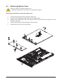
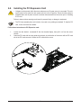
2-1 Removing System Cover
Before you remove or install the system cover
• Make sure the system is not turned on or connected to AC power.
Follow these instructions to remove the system cover:
1. Loosen and remove the screws securing the back cover.
2. Push down the indentation located at the side of the back chassis
3. Slide the cover horizontally to the back using the traction pad and remove the back cover in the
direction of the arrow.
4. Loosen and remove the screws securing the front top cover.
5. Remove the front top cover from the system.
1
4
2
1
3
5

- 15 - Hardware Installation
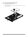
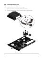
2-2 Removing and Installing the Fan Duct
Follow these instructions to remove/install the fan duct:
1. Lift up to remove the fan duct
2. To install the fan duct, align the fan duct with the guiding groove. Push down the fan duct into
chassis until its rmly seats

Hardware Installation - 16 -
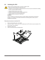
2-3 Installing the CPU
Follow these instructions to install the CPU:
1. Raise the metal locking lever on the socket.
2. Remove the plastic covering on the CPU socket.Insert the CPU with the correct orientation. The
CPU only ts in one orientation.
3. Replace the metal cover.
4. Push the metal lever back into locked position.
1
2
3
4
Read the following guidelines before you begin to install the CPU:
• Make sure that the motherboard supports the CPU.
• Always turn off the computer and unplug the power cord from the power outlet before installing
the CPU to prevent hardware damage.
• Unplug all cables from the power outlets.
• Disconnect all telecommunication cables from their ports.
• Place the system unit on a at and stable surface.
• Open the system according to the instructions.
WARNING!
Failure to properly turn off the server before you start installing componentsmay causeserious
damage. Do not attempt the procedures described in the following sections unless youare a
qualied servicetechnician.

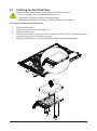
- 17 - Hardware Installation
Follow these instructions to install the heat sinks:
1. Apply thermal compound evenly on the top of the CPU.
Remove the protective cover from the underside of the heat sink.
2. Place the heat sink(s) on top of the CPU and tighten the four positioning screws.
1
2
2-4 Installing the Heat Sink

Hardware Installation - 18 -
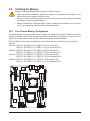
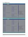
2-5-1 FourChannelMemoryConguration
This motherboard provides eight DDR3 memory sockets and supports Four Channel Technology. After the
memory is installed, the BIOS will automatically detect the specications and capacity of the memory. En-
abling Four Channel memory mode will be four times of the original memory bandwidth.
The four DDR3 memory sockets are divided into four channels each channel has two memory sockets as
following:
Channel 1: DDR3_P0_A0, DDR3_P0_A1, DDR3_P0_A2 (For pimary CPU)
DDR3_P1_E0, DDR3_P1_E1, DDR3_P1_E2 (For secondary CPU)
Channel 2: DDR3_P0_B0, DDR3_P0_B1, DDR3_P0_B2 (For pimary CPU)
DDR3_P1_F0, DDR3_P1_F1, DDR3_P1_F2 (For secondary CPU)
Channel 3: DDR3_P0_C0, DDR3_P0_C1, DDR3_P0_C2 (For pimary CPU)
DDR3_P1_G0, DDR3_P1_G1, DDR3_P1_G2 (For secondary CPU)
Channel 4: DDR3_P0_D0, DDR3_P0_D1, DDR3_P0_D2 (For pimary CPU)
DDR3_P1_H0, DDR3_P1_H1, DDR3_P1_H2 (For secondary CPU)
2-5 Installing the Memory
Read the following guidelines before you begin to install the memory:
• Make sure that the motherboard supports the memory. It is recommended that memory of the
same capacity, brand, speed, and chips be used.
• Always turn off the computer and unplug the power cord from the power outlet before installing
the memory to prevent hardware damage.
• Memory modules have a foolproof design. A memory module can be installed in only one direc-
tion. If you are unable to insert the memory, switch the direction.
DDR3_P0_A0
DDR3_P0_D2
DDR3_P1_F2
DDR3_P1_G0
DDR3_P0_B0
DDR3_P0_C2
DDR3_P1_E2
DDR3_P1_H0
DDR3_P0_B2
DDR3_P0_C0
DDR3_P1_E0
DDR3_P1_H2
DDR3_P0_A1
DDR3_P0_D1
DDR3_P1_F1
DDR3_P1_G1
DDR3_P0_A2
DDR3_P0_D0
DDR3_P1_F0
DDR3_P1_G2
DDR3_P0_B1
DDR3_P0_C1
DDR3_P1_E1
DDR3_P1_H1

- 19 - Hardware Installation
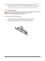
2-4-2 Installing a Memory
Before installing a memory module, make sure to turn off the computer and unplug the power
cord from the power outlet to prevent damage to the memory module.
Be sure to install DDR3 DIMMs on this motherboard.
Follow these instructions to install the Memory:
1. Insert the DIMM memory module vertically into the DIMM slot, and push it down.
2. Close the plastic clip at both edges of the DIMM slots to lock the DIMM module.
3. Reverse the installation steps when you wish to remove the DIMM module.
2
2
1
Due to CPU limitations, read the following guidelines before installing the memory in Four Channel mode.
1. Four Channel mode cannot be enabled if only one DDR3 memory module is installed.
2. When enabling Four Channel mode with two or four memory modules, it is recommended that
memory of the same capacity, brand, speed, and chips be used for optimum performance.

- 20 - Hardware Installation
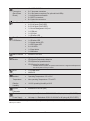
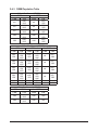
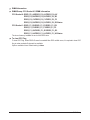
3 Slots Per Channel (RDIMM)
1DPC 2DPC 3DPC
1.35V 1.5V 1.35V 1.5V 1.35V 1.5V
1066,
1333
1066,
1333,
1600
1066,
1333
1066,
1333,
1600
n/a 800,
1066
1066,
1333
1066,
1333,
1600
1066,
1333
1066,
1333,
1600
n/a 800,
1066
1066,
1333
1066,
1333,
1600
1066,
1333
1066,
1333,
1600
n/a 800,
1066
1066,
1333
1066,
1333,
1600
1066,
1333
1066,
1333,
1600
n/a 800,
1066
800 1066 800 800 n/a n/a
800 1066 800 800 n/a n/a
2-4-3 DIMM Population Table
3 Slots Per Channel (UDIMM)
1DPC 2DPC
1.35V 1.5V 1.35V 1.5V
n/a 1066,
1333 n/a 1066,
1333
n/a 1066,
1333 n/a 1066,
1333
n/a 1066,
1333 n/a 1066,
1333
1066 1066,
1333 1066 1066,
1333
1066 1066,
1333 1066 1066,
1333
3 Slots Per Channel (LRDIMM)
1DPC and 2DPC 3DPC
1.35V 1.5V 1.35V 1.5V
1066 1066,
1333 1066 1066
1066 1066,
1333 1066 1066
Page is loading ...
Page is loading ...
Page is loading ...
Page is loading ...
Page is loading ...
Page is loading ...
Page is loading ...
Page is loading ...
Page is loading ...
Page is loading ...
Page is loading ...
Page is loading ...
Page is loading ...
Page is loading ...
Page is loading ...
Page is loading ...
Page is loading ...
Page is loading ...
Page is loading ...
Page is loading ...
Page is loading ...
Page is loading ...
Page is loading ...
Page is loading ...
Page is loading ...
Page is loading ...
Page is loading ...
Page is loading ...
Page is loading ...
Page is loading ...
Page is loading ...
Page is loading ...
Page is loading ...
Page is loading ...
Page is loading ...
Page is loading ...
Page is loading ...
Page is loading ...
Page is loading ...
Page is loading ...
Page is loading ...
Page is loading ...
Page is loading ...
Page is loading ...
Page is loading ...
Page is loading ...
Page is loading ...
Page is loading ...
Page is loading ...
Page is loading ...
Page is loading ...
Page is loading ...
Page is loading ...
Page is loading ...
-
 1
1
-
 2
2
-
 3
3
-
 4
4
-
 5
5
-
 6
6
-
 7
7
-
 8
8
-
 9
9
-
 10
10
-
 11
11
-
 12
12
-
 13
13
-
 14
14
-
 15
15
-
 16
16
-
 17
17
-
 18
18
-
 19
19
-
 20
20
-
 21
21
-
 22
22
-
 23
23
-
 24
24
-
 25
25
-
 26
26
-
 27
27
-
 28
28
-
 29
29
-
 30
30
-
 31
31
-
 32
32
-
 33
33
-
 34
34
-
 35
35
-
 36
36
-
 37
37
-
 38
38
-
 39
39
-
 40
40
-
 41
41
-
 42
42
-
 43
43
-
 44
44
-
 45
45
-
 46
46
-
 47
47
-
 48
48
-
 49
49
-
 50
50
-
 51
51
-
 52
52
-
 53
53
-
 54
54
-
 55
55
-
 56
56
-
 57
57
-
 58
58
-
 59
59
-
 60
60
-
 61
61
-
 62
62
-
 63
63
-
 64
64
-
 65
65
-
 66
66
-
 67
67
-
 68
68
-
 69
69
-
 70
70
-
 71
71
-
 72
72
-
 73
73
-
 74
74


Gigabyte GS-R12PE1 Owner's manual
- Type
- Owner's manual
- This manual is also suitable for
Ask a question and I''ll find the answer in the document
Finding information in a document is now easier with AI
Related papers
-
Gigabyte GA-7PPSH2 Owner's manual
-
-
-
Gigabyte GS-R22PHE User manual
-
-
-
Gigabyte GA-7PESH2 User manual
-
Gigabyte GS-R12P8G Owner's manual
-
-
Other documents
-
Tyan S7056 User Giude
-
Supermicro X9DAE User manual
-
Supermicro X9DRW-CF31 User manual
-
-
-
-
-
-
-