Page is loading ...

OWNER'S MANUAL
LONWORKS GATEWAY
GW-LON(A) - (K05-LON A)
Thank you very much for purchasing our product.
Before using your product, please read this manual carefully and keep it for future
reference.

Contents
I. Installation Diagram ............................................................................. 1
1. Product Dimensions ........................................................................ 1
2. Installation Diagram ......................................................................... 1
II. Specications ..................................................................................... 2
III. LonWorks Gateway Wiring ................................................................ 2
IV. Functions of LonWorks Gateway....................................................... 3
V. LonWorks Communication Objects of LonWorks Gateway ................ 3
1. Communication Objects .................................................................. 3
2. IDU LonWorks Objects .................................................................... 3
2.1 Output Class Variable (Readable) ............................................. 3
2.2 Input Class Variable (Writable) .................................................. 6
2.3 IDU Information Output Class Variable (Readable) of Bus ........ 9
2.4 IDU Group Input Class Variable (Writeable) .............................. 9
3. ODU LonWorks Objects ................................................................. 10
3.1 Output Class Variable (Readable) ............................................ 10
3.2 ODU Information Output Class Variable of Bus ........................ 10
4. Other LonWorks Objects ................................................................ 12
4.1 Version Information Output Class Variable ............................... 12
4.2 Gateway ID Output Class Variable ........................................... 12

1
I. Installation Diagram
1. Product Dimensions
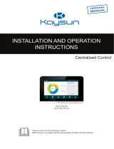
2. Installation Diagram
The product uses the rail-type installation method: rst secure the rail in the packing carton to the
position where the product will be installed, and then fasten the spring of the gateway on the rail.
170 mm
67 mm
34 mm
116 mm
Accessory rail
Sprin
Spring

2
II. Specications
III. LonWorks Gateway Wiring
Input power voltage: 24 V AC;
Operating ambient temperature of modules: 0°C to 50°C;
Operating ambient humidity of modules: RH 25% to RH 90%.
The LonWorks gateway has one set of XYE communication ports, which can be connected to one
XYE bus: up to 32 IDUs (address range: 0-31), and 32 ODUs (8 refrigeration systems, address
range: 00-31).
The LonWorks gateway has one LON bus port, with the channel type TP/FT-10, and it is connected
to the LonWorks BAS network using a free topology twisted pair.
The communication distance of the LON bus and the XYE bus is 800 meters in theory, but this
is affected by the actual installation environment and other factors, so the actual communication
distance may vary according to circumstances.
II. Specifications
III. LonWorks Gateway Wiring
Input power voltage: 24 V AC;
Operating ambient temperature of modules: 0°C to 50°C;
Operating ambient humidity of modules: RH 25% to RH 90%.
The LonWorks gateway has one set of XYE communication ports, which can be connected to one
XYE bus: up to 32 IDUs (address range: 0-31), and 32 ODUs (8 refrigeration systems, address
range: 00-31).
The LonWorks gateway has one LON bus port, with the channel type TP/FT-10, and it is connected
to the LonWorks BAS network using a free topology twisted pair.
The communication distance of the LON bus and the XYE bus is 800 meters in theory, but this is
affected by the actual installation environment and other factors, so the actual communication
distance may vary according to circumstances.
2
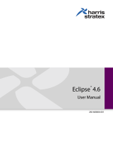
Reserved C R
X Y E
Lon+ Lon- Reserved
1
2
3
POWER
XYE
No. Name Remarks
24VAC, 50/60Hz, 200mA
To ODU XYE port
LON+ LON-
SVC1 SVC2
LON bus port to BMS
Service indicator light
RST1 RST2 Reset indicator light
4
5
No. Name Remarks
1POWER 24VAC, 50/60Hz, 200mA
2XYE To ODU XYE port
3LON+ LON- LON bus port to BMS
4SVC1 SVC2 Service indicator light
5RST1 RST2 Reset indicator light

3
IV. Functions of LonWorks Gateway
V. LonWorks Communication Objects of LonWorks
Gateway
The LonWorks gateway is embedded with a LonWorks function module that supports the LonTalk
protocol. The LonWorks gateway can transform 485 communication protocol into a standard
LonTalk protocol, thus achieving integration between the central air conditioning system and
LonWorks' BAS.
The new LonWorks gateway supports a total of 512 objects which can be connected to 32 IDUs
and 32 ODUs. The specic parameters are shown in the following table.
Output class variables are readable variables read by the LonWorks gateway from an IDU.
1) Operating mode
Variable name: nvo_Op_Mode
Parameter denition
Variable format:
1. Communication Objects
2. IDU LonWorks Objects
2.1 Output Class Variable (Readable)
Mode
0Off
1 Fan
2 Cooling
3 Heating
4 Reserved
5 Water heating
6 Dry
18 Automatic cooling
19 Automatic heating
30 Auto

4
In the variable format, values other than the mode are not dened, and 0 is always displayed.
When the IDU is ofine, the value of the variable is 0.
Note: M represents the IDU address, nvo_Op_Mode_1 represents the operating mode of IDU #0,
and so on. Of these, nvo_Op_Mode _1 to nvo_Op_Mode _16 of the sub0 main board represent the
operating modes of IDUs #0-15, and nvo_Op_Mode _17 to nvo_Op_Mode _32 of the sub1 main
board represent the operating modes of IDUs #16-31.
2) Operating fan speed
Variable name: nvo_Fan_Speed
Parameter denition:
When the IDU is ofine, the value of the variable is 0.
Note: M represents the IDU address, nvo_Fan_Speed _1 represents the operating fan speed of
IDU #0, and so on. Of these, nvo_Fan_Speed _1 to nvo_Fan_Speed _16 of the sub0 main board
represent the operating fan speeds of IDUs #0-15, and nvo_Fan_Speed _17 to nvo_Fan_Speed _32
of the sub1 main board represent the operating fan speeds of IDUs #16-31.
3) Set temperature
Variable name: nvo_Temp_Set
Parameter denition: indicates the set temperature/automatic mode cooling set temperature/hydraulic
module heating water temperature. For example, 17-80 indicates 17ºC to 80ºC.
When the IDU is ofine, the value of the variable is 0.
4) Heating temperature
Variable name: nvo_Heating_Set
Parameter denition: indicates the automatic heating temperature/hydraulic module heating
temperature. For example, 17-80 indicates 17°C to 80°C.
When the IDU is ofine, the value of the variable is 0.
Fan speed
0 Fan off
1 Fan speed 1
2 Fan speed 2
3 Fan speed 3
4 Fan speed 4
5 Fan speed 5
6 Fan speed 6
7 Fan speed 7
20 Low
21 Medium
22 High
30 Automatic

5
5) Room temperature (hydraulic module water tank temperature)
Variable name: nvo_Room_Set
Parameter denition: indicates the room temperature/hydraulic module water tank temperature. For
example, -25-105°C indicates -25°C to +105°C.
When the IDU is ofine, the value of the variable is 0.
6) Water outlet temperature (hydraulic module)
Variable name: nvo_Water_Set
Parameter denition: indicates the water outlet temperature (hydraulic module). For example, -25-
105°C indicates -25°C to +105°C.
When the IDU is ofine, the value of the variable is 0.
7) IDU error
Variable name: nvo_Fault_Code
Parameter denition: indicates the high/low byte of an error code.
When the IDU is ofine, the value of the variable is 0.
Refer to the following list for error codes:
0: No error
1-20: A0-AF, AH, AL, AP, AU
21-40: b0-bF, bH, bL, bP, bU
41-60: C0-CF, CH, CL, CP, CU
61-80: E0-EF, EH, EL, EP, EU
81-100: F0-FF, FH, FL, FP, FU
101-120: H0-HF, HH, HL, HP, HU
121-140: L0-LF, LH, LL, LP, LU
141-160: J0-JF, JH, JL, JP, JU
161-180: n0-nF, nH, nL, nP, nU
181-200: P0-PF, PH, PL, PP, PU
201-220: r0-rF, rH, rL, rP, rU
221-240: t0-tF, tH, tL, tP, Tu
241-260: U0-UF, UH, UL, UP, UU
Others: reserved
The error displayed on certain models may not be consistent with the unit's actual error. In these
cases, refer to the error on the unit. For the meaning of a specic error code, see the explanation
provided in the service manual.
Error codes 121-140 are only used for the debugging function. Codes 141-240 indicate a reserved
error, and 241-255 indicate reserved byte.

6
There are four kinds of LonWorks objects in the IDU, which can be used by the host of the
LonWorks BAS.
1) Setting the mode
Variable name: nvi_Op_Mode
Parameter denition:
Note: M represents the IDU address, nvi_Op_Mode _1 represents the mode setting of IDU #0,
and so on. Of these, nvi_Op_Mode _1 to nvi_Op_Mode _16 of the main board represent the
mode settings of IDUs #0-15, and nvi_Op_Mode _17 to nvi_Op_Mode _32 of the sub main board
represent the mode settings of IDUs #16-32.
By default, the mode setting is processed as mode + boot. If the upper computer sends a value that
is not dened, mode setting is not performed by default.
2) Setting the fan speed
Variable name: nvi_Fan_Speed
Parameter denition:
2.2 Input Class Variable (Writable)
Mode
0Off (Heating/water heating off for
European three-pipe models)
1 Fan on
2 Cooling on
3 Heating on
4 Reservation on
5 Heating water on
6 Dry on
7 Heating/heating water on
8 Heating off
8 Heating water off
30 Auto

7
Fan
speed
0 Fan off
1 Fan speed 1
2 Fan speed 2
3 Fan speed 3
4 Fan speed 4
5 Fan speed 5
6 Fan speed 6
7 Fan speed 7
20 Low
21 Medium
22 High
30 Automatic
Note: M represents the IDU address, nvi_Fan_Speed_1 represents the fan speed setting of IDU #0,
and so on. Of these, nvi_Fan_Speed _1 to nvi_Fan_Speed_16 of the sub0 main board represent
the fan speed settings of IDUs #0-15 IDUs, and nvi_Fan_Speed _16 to nvi_Fan_Speed_32 of the
sub1 main board represent the fan speed settings of IDUs #16-31.
If the upper computer sends a value that is not dened, the fan speed setting is not performed by
default.
If nvi_Op_Mode_M selects the Off or Dry mode, the set values of nvi_Fan_Speed_M are invalid.
If nvi_Op_Mode_M selects the Heating mode, the IDU may not be able to respond to medium/high
speed commands due to the cold air protection function.
3) Setting the temperature
Set temperature/automatic mode cooling set temperature/hydraulic module heating water
temperature(Common IDU: 17°C to 30°C; high-temperature hydraulic module: 25°C to 80°C)
Variable name: nvi_TempSet_M
Parameter denition:
Note: M represents the IDU address, nvi_TempSet _1 represents the temperature setting of IDU
#0, and so on. Of these, nvi_TempSet _1 to nvi_TempSet _16 of the sub0 main board represent the
temperature settings of IDUs #0-15, and nvi_TempSet _16 to nvi_TempSet _32 of the sub1 main
board represent the temperature settings of IDUs #16-31.
When the upper computer sends a value other than the dened values, the minimum temperature
is implemented if the value is below the minimum value, while the maximum temperature is
implemented if the value is higher than the maximum temperature.
If the upper computer sends a temperature value with decimal places, only the integer is used. For
example, 67.68°C is sent as 67°C.
If nvi_TempSet _M selects the Off or Fan mode, the set values of nvi_TempSet _M are invalid.

8
4) Setting the heating temperature
Automatic heating temperature/hydraulic module heating temperature (Common IDU: 17°C to 30°C;
high-temperature hydraulic module: 25°C to 80°C)
Variable name: nvi_Heating_Set_M
Parameter denition:
Note: M represents the IDU address, nvi_Heating_Set _1 represents the temperature setting of
IDU #0, and so on. Of these, nvi_Heating_Set _1 to nvi_Heating_Set _16 of the sub0 main board
represent the temperature settings of IDUs #0-15, and nvi_Heating_Set _16 to nvi_Heating_Set
_32 of the sub1 main board represent the temperature settings of IDUs #16-31.
When the upper computer sends a value other than the dened values, the minimum temperature
is implemented if the value is below the minimum value, while the maximum temperature is
implemented if the value is higher than the maximum temperature.
If the upper computer sends a temperature value with decimal places, only the integer is used. For
example, 67.68°C is sent as 67°C.
If nvi_TempSet _M selects the Off or Fan mode, the set values of nvi_TempSet _M are invalid.
Temperature
(Celsius) Value - LonMaker Temperature
(Celsius) Value - LonMaker
17 17 25 25
18 18 26 26
19 19 27 27
20 20 28 28
21 21 29 29
22 22 30 30
23 23 ... ...
24 24 80 80

9
1) Online status
Variable name: nvo_Online_Stat
Parameter denition: Each bit represents one IDU where "0" means the unit is ofine, and "1"
means the unit is online.
Notes: nvo_Online_Stat of the sub0 main board represents the online status of IDUs #0-15, and
nvo_Online_Stat of the sub1 main board represents the online status of IDUs #16-31.
2) Operating status
Variable name: nvo_Op_Stat
Parameter denition: Each bit represents one IDU where "0" means the unit is OFF, and "1" means
the unit is ON.
Notes: nvo_Op_Stat of the sub0 main board represents the operating status of IDUs #0-15, and
nvo_Op_Stat of the sub1 main board represents the operating status of IDUs #16-31.
3) Error status
Variable name: nvo_Fault_Stat
Parameter denition: Each bit represents one IDU where "0" means the unit has no error, and "1"
means the unit has an error.
Notes: nvo_Fault_Stat of the sub0 main board represents the error status of IDUs #0-15, and nvo_
Fault_Stat of the sub1 main board represents the error status of IDUs #16-31.
1) Setting group control power-off
Variable name: nvi_GroupControl
Parameter denition:
If the upper computer sends other values, the LonWorks gateway will not process them.
If the upper computer sends the variables of the sub0 main board, it will only send the group control
power-off command to the IDU connected to the main board. If the upper computer sends the
variables of the sub1 main board, it will only send the group control power-off command to the IDU
connected to the sub main board.
2.3 IDU Information Output Class Variable (Readable) of Bus
2.4 IDU Group Input Class Variable (Writeable)
Status Value
Off 100.00

10
There is only one LonWorks object in the ODU, which can be used by the host of the LonWorks BAS.
1) ODU error codes
Variable name: nvo_Fault_Code1
Parameter denition:
0: no error
1–20: A0–AF, AH, AL, AP, AU
21–40: b0–bF, bH, bL, bP, bU
41–60: C0–CF, CH, CL, CP, CU
61–80: E0–EF, EH, EL, EP, EU
81–100: F0–FF, FH, FL, FP, FU
101–120: H0–HF, HH, HL, HP, HU
121–140: L0–LF, LH, LL, LP, LU
141–160: J0–JF, JH, JL, JP, JU
161–180: n0–nF, nH, nL, nP, nU
181–200: P0–PF, PH, PL, PP, PU
201–220: r0–rF, rH, rL, rP, rU
221–240: t0–tF, tH, tL, tP, tU
241–260: U0–UF, UH, UL, UP, UU
Others: reserved
For the meaning of a specic error code, see the explanation provided in the service manual.
When the ODU is ofine, the value of the variable is 0.
Note: M represents the ODU address, nvo_Fault_Code1_1 represents the error code of ODU #0, and
so on. Of these, nvo_Fault_Code1_1 to nvo_Fault_Code1_16 of the sub0 main board represent the
error codes of ODUs #0-15, and nvo_Fault_Code1_1 to nvo_Fault_Code1_32 of the sub1 main board
represent the error codes of ODUs #16-31.
1) Online status
Variable name: nvo_Online_Stat1
Parameter denition: Each bit represents one ODU where "0" means the unit is ofine, and "1" means
the unit is online.
Notes: nvo_Online_Stat1 of the sub0 main board represents the online status of ODUs #0-15, and
nvo_Online_Stat1 of the sub1 main board represents the online status of ODUs #16-31.
3. ODU LonWorks Objects
3.1 Output Class Variable (Readable)
3.2 ODU Information Output Class Variable of Bus

11
2) Operating status
Variable name: nvo_Op_Stat1
Parameter denition: Each bit represents one ODU where "0" means the unit is OFF, and "1" means
the unit is ON.
Notes: nvo_Op_Stat1 of the sub0 main board represents the operating status of ODUs #0-15, and
nvo_Op_Stat1 of the sub1 main board represents the operating status of ODUs #16-31.
3) Error status
Variable name: nvo_Fault_Stat1
Parameter denition: Each bit represents one ODU where "0" means the unit has no error, and "1"
means the unit has an error.
Notes: nvo_Fault_Stat1 of the sub0 main board represents the error status of ODUs #0-15, and nvo_
Fault_Stat1 of the sub1 main board represents the error status of ODUs #16-31.

Variable name: nvo_Version
Parameter denition: displays the version of the current LON module.
Variable name: nvo_Gateway_Id
Parameter denition: outputs the network variable nvo_Gateway_Id to display the ID (1 or 2) of the
current gateway.
ID 1: manages IDU/ODU #0-15.
ID 2: manages IDU/ODU #16-31.
4. Other LonWorks Objects
4.1 Version Information Output Class Variable
4.2 Gateway ID Output Class Variable
12

WP-MD20U-037A-EN
16110800000508 V.A

/