Page is loading ...

1
- Do not store or use gasoline or other flam-
mable vapors and liquids in the vicinity of this
or any other appliance.
-What to do if you smell gas
Do not try to light any appliance.
Do not touch any electrical switch.
Do not use any phone in your building.
Immediately call your gas supplier from a
neighbor's phone. Follow the gas supplier's
instructions.
If you cannot reach your gas supplier, call
the fire department.
- Installation and service must be performed by a
qualified installer, service agency, or the gas
supplier.
Models:
7000TV
6000TVB
Installers Guide
WARNING: IMPROPER INSTALLA-
TION, ADJUSTMENT, ALTERATION,
SERVICE OR MAINTENANCE CAN
CAUSE INJURY OR PROPERTY DAM-
AGE. REFER TO THIS MANUAL. FOR
ASSISTANCE OR ADDITIONAL INFOR-
MATION CONSULT A QUALIFIED IN-
STALLER, SERVICE AGENCY, OR THE
GAS SUPPLIER.
Underwriters
Laboratories Listed
522-902F 9/00
READ THIS MANUAL BEFORE INSTALLING OR
OPERATING THIS APPLIANCE. THIS INSTALLERS
GUIDE MUST BE LEFT WITH APPLIANCE FOR
FUTURE REFERENCE.
Please contact your Heat-N-Glo dealer for any
questions or concerns. For the number of your
nearest Heat-N-Glo dealer, please call 952-985-6000.
Printed in U.S.A. Copyright 2000,
Heat-N-Glo, a division of Hearth Technologies Inc.
20802 Kensington Boulevard, Lakeville, MN 55044
WARNING: IF THE INFORMATION
IN THESE INSTRUCTIONS IS NOT
FOLLOWED EXACTLY, A FIRE OR
EXPLOSION MAY RESULT CAUS-
ING PROPERTY DAMAGE, PER-
SONAL INJURY, OR DEATH.
This product is covered by one or more of the following patents: (United States) 4,112,913; 4,408,594; 4,422,426; 4,424,792; 4,520,791; 4,793,322;
4,852,548; 4,875,464; 5,000,162; 5,016,609; 5,076,254 5,191,877; 5,218,953; 5,328,356; 5,429,495; 5,452,708; 5,542,407; 5,613,487; (Australia)
543790; 586383; (Canada) 1,123,296; 1,297,746; 2,195,264; (Mexico) 97-0457; (New Zealand) 200265; or other U.S. and foreign patents pending.

2
These units MUST use one of the vent systems
described in the Installing the Fireplace section of
the Installers Guide. NO OTHER vent systems or
components MAY BE USED.
This gas fireplace and vent assembly MUST be
vented directly to the outside and MUST NEVER be
attached to a chimney serving a separate solid fuel
burning appliance. Each gas appliance MUST USE
a separate vent system. Common vent systems are
PROHIBITED.
INSPECT the external vent cap on a regular basis to
make sure that no debris is interfering with the air
flow.
The glass door assembly MUST be in place and
sealed, and the trim door assembly MUST be in
place on the fireplace before the unit can be placed
into safe operation.
DO NOT OPERATE this appliance with the glass
door removed, cracked, or broken. Replacement of
the glass door should be performed by a licensed
or qualified service person. DO NOT strike or slam
the glass door.
The glass door assembly SHALL ONLY be
replaced as a complete unit, as supplied by the gas
fireplace manufacturer. NO SUBSTITUTE material
may be used.
DO NOT USE abrasive cleaners on the glass door
assembly. DO NOT ATTEMPT to clean the glass
door when it is hot.
Turn off the gas before servicing this appliance. It is
recommended that a qualified service technician
perform an appliance check-up at the beginning of
each heating season.
Any safety screen or guard removed for servicing
must be replaced before operating this appliance.
READ and UNDERSTAND all instructions carefully
before starting the installation. FAILURE TO
FOLLOW these installation instructions may result
in a possible fire hazard and will void the warranty.
Prior to the first firing of the fireplace, READ the
Using Your Fireplace section of the Owners Guide.
DO NOT USE this appliance if any part has been
under water. Immediately CALL a qualified service
technician to inspect the unit and to replace any part
of the control system and any gas control which has
been under water.
THIS UNIT IS NOT FOR USE WITH SOLID FUEL.
Installation and repair should be PERFORMED by a
qualified service person. The appliance and venting
system should be INSPECTED before initial use
and at least annually by a professional service
person. More frequent cleaning may be required
due to excessive lint from carpeting, bedding
material, etc. It is IMPERATIVE that the units
control compartment, burners, and circulating air
passageways BE KEPT CLEAN to provide for
adequate combustion and ventilation air.
Always KEEP the appliance clear and free from
combustible materials, gasoline, and other
flammable vapors and liquids.
NEVER OBSTRUCT the flow of combustion and
ventilation air. Keep the front of the appliance
CLEAR of all obstacles and materials for servicing
and proper operations.
Due to the high temperature, the appliance should
be LOCATED out of traffic areas and away from
furniture and draperies. Clothing or flammable
material SHOULD NOT BE PLACED on or near the
appliance.
Children and adults should be ALERTED to the
hazards of high surface temperature and should
STAY AWAY to avoid burns or clothing ignition.
Young children should be CAREFULLY SUPERVISED
when they are in the same room as the appliance.
!
!
!
!
!
!
!
!!
!
!
!
!
!
!
!
!
SAFETY AND WARNING INFORMATION
!

3
TABLE OF CONTENTS
Safety and Warning Information. ............................................... 2
Service Parts Lists. .................................................................... 4
Section 1: Approvals and Codes. .............................................. 8
Approval Listings and Codes ........................................................ 8
Appliance Certification................................................................... 8
Installation Codes .......................................................................... 8
High Altitude Installations ............................................................... 8
Section 2: Getting Started ......................................................... 9
Introducing the Heat-N-Glo Gas Fireplaces .................................. 9
Pre-installation Preparation ........................................................... 9
Section 3: Installing the Fireplace. .......................................... 11
Step 1 Locating the Fireplace .................................................. 11
Step 2 Framing the Fireplace ................................................... 11
Step 3 Negative Pressure Make-up Air ................................... 12
Step 4 Installing the Vent System ............................................ 13
A. Vent System Approvals ........................................... 13
B. System Components ............................................. 13
C. Bedroom Installation in Canada ............................. 14
D. Vent Termination .................................................... 14
Step 5 Positioning, Leveling, and
Securing the Fireplace................................................. 14
Step 6 The Gas Control Systems ........................................... 14
Step 7 The Gas Supply Line ................................................... 15
Step 8 Gas Pressure Requirements ...................................... 15
Step 9 Wiring the Fireplace .................................................... 16
Step 10 Finishing ...................................................................... 18
Step 11 Installing Trim, Logs, and Ember Material.................... 18
Installing the Trim ......................................................... 18
Positioning the Logs .................................................... 18
Placing the Ember Material .......................................... 18
Step 12 Before Lighting the Fireplace ....................................... 19
Step 13 Lighting the Fireplace .................................................. 19
After the Installation ..................................................................... 19
Section 4: Maintaining and Servicing Your Fireplace. ........ 20
u = Contains updated information.
u

8
Appliance Certification
The Heat-N-Glo fireplace models discussed in this Installers
Guide have been tested to certification standards and listed
by the applicable laboratories.
Certification
MODELS: 7000TV, 6000TVB
LABORATORY: Underwriters Laboratories
TYPE: Direct Vent Gas Fireplace
STANDARD: ANSI Z21.50CGA2.2
Installation Codes
The fireplace installation must conform to local codes. Before
installing the fireplace, consult the local building code
agency to ensure that you are in compliance with all
applicable codes, including permits and inspections.
In the absence of local codes, the fireplace installation must
conform to the National Fuel Gas Code ANSI Z223.1 (in
the United States) or the CAN/CGA-B149 Installation Codes
(in Canada). The appliance must be electrically grounded
in accordance with local codes or, in the absence of local
codes with the National Electric Code ANSI/NFPA No. 70
(in the United States), or to the CSA C22.1 Canadian Electric
Code (in Canada).
These models (natural gas and propane) can be installed in
a bedroom (in the United States) which has a total volume
of unconfined space appropriate to the particular installation.
Refer to the National Fuel Gas Code ANSI Z223.1/NFPA54
1Approvals and
Codes
(current edition). The Uniform Mechanical Code - (current
edition), and local Building Officials for the options allowed
in obtaining an effective bedroom volume of unconfined
space.
These models (natural gas and propane) can be installed in
a bedroom (in Canada) if a thermostat (Model WH-STAT) is
installed with the unit. Consult local code authorities.
Detailed installation instructions for Model WH-STAT are
included with the kit.
High Altitude Installations
U.L. Listed gas fireplaces are tested and approved for
elevations from 0 to 2,000 feet in the U.S.A. and from 0 to
4,500 feet in Canada.
When installing this fireplace at an elevation above 2,000
feet (in the United States), it may be necessary to decrease
the input rating by changing the existing burner orifice to a
smaller size. Input should be reduced four percent (4%) for
each 1,000 feet above sea level, unless the heating value of
the gas has been reduced, in which case this general rule
will not apply. To identify the proper orifice size, check with
the local gas utility.
When installing this fireplace at an elevation between 2,000
and 4,500 feet (in Canada), the input rating must be reduced
by ten percent (10%).
When installing this fireplace at an elevation above 4,500
feet (in Canada), check with local authorities.
Consult your local gas utility for assistance in determining
the proper orifice for your location.
Heat-N-Glo Quality
Systems registered
by SGS ICS

9
2Getting Started
Introducing the Heat-N-Glo Gas Fireplaces
Heat-N-Glo B-type vent gas fireplaces are designed to op-
erate with all exhaust gases expelled to the outside of the
building.
The information contained in this Installers Guide, unless
noted otherwise, applies to all models and gas control
systems. Gas fireplace diagrams, including the dimensions,
are shown in this section.
Pre-install Preparation
This gas fireplace and its components are tested and safe
when installed in accordance with this Installers Guide.
Report to your dealer any parts damaged in shipment,
particularly the condition of the glass. Do not install any
unit with damaged, incomplete, or substitute parts.
The vent system components, gas logs and trim doors are
shipped in separate packages. Log installation instructions
are provided in the manual bag assembly shipped with the
unit.
Read all of the instructions before starting the
installation. Follow these instructions carefully during
the installation to ensure maximum safety and benefit.
Failure to follow these instructions will void the
owners warranty and may present a fire hazard.
The Heat-N-Glo Warranty will be voided by, and Heat-N-Glo
disclaims any responsibility for, the following actions:
Installation of any damaged fireplace or vent system
component.
Modification of the fireplace or direct vent system.
Installation other than as instructed by Heat-N-Glo.
Improper positioning of the gas logs or the glass door.
Installation and/or use of any component part not manu-
factured and approved by Heat-N-Glo, not withstanding
any independent testing laboratory or other party approval
of such component part or accessory.
ANY SUCH ACTION MAY POSSIBLY CAUSE A FIRE
HAZARD.
When planning a fireplace installation, its necessary to
determine:
Where the unit is to be installed.
The vent system configuration to be used.
Gas supply piping.
Electrical wiring.
Framing and finishing details.
Whether optional accessoriesdevices such as a fan,
wall switch, or remote controlare desired.
If the fireplace is to be installed on carpeting or tile, or on
any combustible material other than wood flooring, the
fireplace should be installed on a metal or wood panel that
extends the full width and depth of the fireplace.


11
3Installing the Fireplace
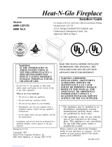
Step 1. Locating the Fireplace
The diagram below shows space and clearance require-
ments for locating a fireplace within a room.
ABCD E
42 22 36 51 72
Minimum Clearances
from the Fireplace to Combustible Materials
Inches mm
Glass Front ........................ 36 .................... 914
Floor ................................... 0 ....................... 0
Rear ...................................1/2 ..................... 13
Sides .................................1/2 ..................... 13
Top ................................... 3 1/2 ................... 89
Ceiling* .............................. 31 .................... 787
Figure 2. Fireplace Dimensions, Locations,
and Space Requirements
Clearance Requirements
The top, back, and sides of the fireplace are defined by
stand-offs. The minimum clearance to a perpendicular wall
extending past the face of the fireplace is one inch (25
mm). The back of the fireplace may be recessed 21 1/2
inches (546 mm) into combustible construction.
The minimum clearance from the top face of the fireplace to
combustible finishing materials such as drywall, is one inch
(25mm).
The distance from the unit to combustible construction
is to be measured from the unit outer wrap surface to
the combustible construction, NOT from the screw
heads that secure the unit together. A. 42 B. 38 1/2 C. 22
Figure 3. Framing Dimensions
Minimum Clearances from the B-Type Vent Pipe to
Combustible Materials is 1 inch (25mm) all around the
pipe.
Step 2. Framing the Fireplace
Fireplace framing can be built before or after the fireplace is
set in place. Framing should be positioned to accommo-
date wall coverings and fireplace facing material. The dia-
gram below shows framing reference dimensions.
CAUTION: MEASURE FIREPLACE DIMENSIONS AND
VERIFY FRAMING METHODS AND WALL COVERING
DETAILS BEFORE FRAMING.
* The clearance to the ceiling is measured from the top
of the unit, excluding the standoffs (see Figure 13).
Framing should be constructed of 2 X 4 lumber or heavier.
WARNING:
To ensure proper clearances
the front framing header
must be installed on its
narrow edge and to the front
of the frame.

12
Step 3. Negative Pressure Make-up Air
Negative Pressure warning: When negative pressure is
present, an atmospherically vented fireplace (with a draft
hood) may not function properly and it may down draft. In
the case of a gas appliance, spillage of the combustion
gases may occur. This may create a dangerous carbon
monoxide situation in the house.
The causes of negative pressure to a house can include
the following:
Stack effect in the building.
Exhaust only appliances (mechanically and
atmospherically vented).
Inadequate make-up air (which is increasingly
more prevalent in new construction).
NOTE: This fireplace will operate correctly only if adequate
ventilation is provided to allow proper draft to the fireplace
system. Heat-N-Glo assumes no responsibility for the
improper performance of the fireplace system caused by
inadequate draft due to environmental conditions, down
drafts, tight sealing construction of the structure, or
mechanical exhausting devices which create a negative air
pressure within the structure where the fireplace is located.
It is recommended that all natural venting non-air tight gas
fireplaces have outside air connected to them. It is also
recommended that the building be mechanically or passively
balanced to allow atmospherically vented appliances, such
as top vented gas fireplaces with draft hoods, to draft
properly. If the home experiences negative pressure or is
likely to experience negative pressure, connection to an
outside air source is mandatory.
Installing Optional Outside Make-up Air:
This unit is equipped to accept outside air. By using outside
make-up air, the amount of room air used for combustion
will be reduced. It is recommended that an AK-TV air kit be
used with this appliance.
WARNING: IN A NEGATIVE PRESSURE CON-
DITION (LIKELY TO OCCUR IN NEW HOMES
THAT DO NOT HAVE ADEQUATE MAKE-UP
AIR) THE OUTSIDE AIR KIT MUST BE IN-
STALLED TO OBTAIN PROPER PERFOR-
MANCE AND TO HELP PREVENT SPILLAGE
OF COMBUSTION GASES.
Air Damper
Before lighting the burner, open the damper. Close the
damper when the burner is off.
Detailed installation instructions for Model AK-TV Outside
Air kit are found in the kit.
Figure 4. Make-up Air
!
A 4-inch side collar/damper (found in AK-TV Kit) must be
installed on the fireplace by attaching the side collar to the
outer wrap of the fireplace at the right-hand rear corner using
sheetmetal screws. See Figure 4. Attach one end of a 4-
inch flexible air duct (not provided in the AK-TV Kit) to the
side collar and the other end of the duct to the make-up air
termination cap. Use plastic tie straps to secure the ends
of the flex duct to each collar.

13
!
!
Step 4. Installing the Vent System
A. Vent System Approvals
Models 7000TV and 6000TVB are approved to use 6-inch
(152mm) diameter B-type vent. B-type vent must be used
when the vent system is within combustible construction.
These models may also use single wall rigid or flexible gas
vent IF and ONLY IF the vent system is installed within
non-combustible construction such as a masonry chimney.
The same diameter noted above for B-type vent must be
used for single-wall vent. See Figure 5.
For B-type vent the clearance to combustibles is 1-inch.
Follow vent manufacturers REQUIRED clearances.
The flame and ember appearance may vary based on the
type of fuel burned and the venting configuration used.
B. System Components.
Vent System Configuration
RISE TO RUN RATIO = 2:1
MAXIMUM TOTAL HORIZONTAL RUN = 15 FT.
MINIMUM TOTAL VERTICAL RISE = 9 FT.
MAXIMUM NO. Of ELBOWS: 2 - 90o or 4 - 45o
Plan and install the vent system using the parameters shown
above.
WARNING: YOU MUST NOT EXCEED THESE
PARAMETERS.
Connect a B-Type vent component to the flue outlet collar.
Look at the vent pipe through the holes in the 10 5/8 ring to
check that the vent pipe is attached.
NOTE: It is always better to first attach a straight section
of vent to the unit before attaching an elbow. Avoid
using elbows in the vent system if possible.
A 90-degree elbow can be attached directly to the unit. If it
is, it can be followed by a MAXIMUM 15-feet horizontal
run, a second 90-degree elbow ending in a minimum 30
foot vertical.
A minimum of 9 foot vertical rise ending in a listed termination
cap is required for the unit.
Continue to add vent components, until the vent run is
completed.
WARNING: YOU MUST NOT EXCEED A TOTAL
MAXIMUM HORIZONTAL RUN OF 15 FEET FOR
THE ENTIRE VENT SYSTEM.
LISTED
TERMINATION CAP
LISTED
TERMINATION CAP
LISTED SINGLE-WALL
GAS VENT
LISTED SINGLE-WALL
GAS VENT
NON-COMBUSTIBLE
CONSTRUCTION
NON-COMBUSTIBLE
CONSTRUCTION
B-TYPE
VENT
B-TYPE
VENT
Figure 5. Vent System Attachment
MINIMUM VERTICAL RISE = 9FT
MAXIMUM HORIZONTAL RUN = 15FT
V:H = 2:1
!
NOTE: The vent termination must be in a vertical posi-
tion and the termination cap must be listed for the
vent pipe used.
Consult Local Building Code Officials and Codes for proper
vent system installations.
WARNING: THIS GAS FIREPLACE MUST NEV-
ER BE VENTED BY CONNECTING TO A CHIM-
NEY FLUE SERVING A SEPARATE SOLID FUEL
BURNING APPLIANCE.

14
!
C. Bedroom Installation in Canada
This model MUST NOT be vented into a vent system in-
stalled exterior to a building. The part of the vent system
above the roof line can be exterior to the building.
D. Vent Termination
WARNING: MAJOR U.S. BUILDING CODES
SPECIFY MINIMUM CHIMNEY AND/OR VENT
HEIGHT ABOVE THE ROOF TOP. THESE MIN-
IMUM HEIGHTS ARE NECESSARY IN THE IN-
TEREST OF SAFETY. FIGURE 6 AND TABLE
SHOW MINIMUM HEIGHTS, PROVIDED THE
TERMINATION CAP IS AT LEAST 8-FEET
FROM A VERTICAL WALL.
!
ROOF PITCH H (MIN.) FT.
FLAT TO 6/12 1.0
6/12 TO 7/12 1.25
OVER 7/12 TO 8/12 1.5
OVER 8/12 TO 9/12 2.0
OVER 9/12 TO 10/12 2.5
OVER 10/12 TO 11/12 3.25
OVER 11/12 TO 12/12 4.0
OVER 12/12 TO 14/12 5.0
OVER 14/12 TO 16/12 6.0
OVER 16/12 TO 18/12 7.0
OVER 18/12 TO 20/12 7.5
OVER 20/12 TO 21/12 8.0
Figure 6. Vent Termination
TERMINATION
CAP
12 X
ROOF PITCH
IS X/ 12
LOWEST
DISCHARGE
OPENING
H (MIN.) - MINIMUM HEIGHT FROM ROOF
TO LOWEST DISCHARGE OPENING
Step 5. Positioning, Leveling, and
Securing the Fireplace
To properly position, level, and secure the fireplace:
Place the fireplace into position (see Figure 7).
Level the fireplace from side to side and from front to
back.
Shim the fireplace with non-combustible material, such
as sheet metal, as necessary.
Secure the fireplace to the framing by nailing or screwing.
!
!
Figure 7. Proper Positioning, Leveling,
and Securing of a Fireplace
Step 6. The Gas Control Systems
WARNING: THIS UNIT IS NOT FOR USE WITH
SOLID FUEL.
Two types of gas control systems are used with these mod-
els: Standing Pilot Ignition and Direct Spark Ignition (DSI).
Standing Pilot Ignition System
This system includes millivolt control valve, standing pilot,
thermopile/thermocouple flame sensor, and piezo ignitor.
WARNING: 110-120 VAC MUST NEVER BE
CONNECTED TO A CONTROL VALVE IN A
MILLIVOLT SYSTEM.
Direct Spark Ignition (DSI) System
The DSI system includes a 120V control valve, electronic
module, and spark ignitor/flame sensor.
WARNING: CONTINUOUS 110-120 VAC SER-
VICE MUST BE WIRED TO THE FIREPLACE
JUNCTION BOX IN A DSI SYSTEM.
WARNING:
To ensure proper clearances
the front framing header
must be installed on its
narrow edge and to the
front of the frame.

15
Figure 9. Gas Supply Line
Insert insulation from the outside of the fireplace and
pack the insulation tightly to totally seal between the
pipe and the outer casing.
At the gas line access hole the gap between the supply
piping and gas access hole can be plugged with non-
combustible insulation to prevent cold air infiltration.
Step 7. The Gas Supply Line
NOTE: Have the gas supply line installed in accordance
with local building codes by a qualified installer
approved and/or licensed as required by the locality.
NOTE: Before the first firing of the fireplace, the gas
supply line should be purged of any trapped air.
NOTE: Consult local building codes to properly size
the gas supply line leading to the 1/2 inch
(13 mm) hook-up at the unit.
This gas fireplace is designed to accept a 1/2 inch
(13 mm) gas supply line.
To install the gas supply line:
A listed (and State of Massachusetts approved) 1/2 inch
(13mm) tee-handle manual shut-off valve and a listed flex-
ible gas connector are connected to the 1/2 inch (13mm)
inlet of the control valve. NOTE: If substituting for these
components, please consult local codes for compliance.
Locate the gas line access hole in the outer casing of
the fireplace.
The gas line may be run from either side of the fireplace
provided the hole in the outer wrap does not exceed 2 in
diameter and it does not penetrate the actual firebox.
!
Step 8. Gas Pressure Requirements
Pressure requirements for Heat-N-Glo gas fireplaces
are shown in the table below.
Pressure Natural Gas Propane
Minimum 5.0 inches 11.0 inches
Inlet Pressure w.c. w.c.
Maximum Inlet 14.0 inches 14.0 inches
Gas Pressure w.c. w.c.
Manifold 3.5 inches 10.0 inches
Pressure w.c. w.c.
A one-eighth (1/8) inch (3 mm) N.P.T. plugged tapping is
provided on the inlet and outlet side of the gas control for a
test gauge connection to measure the manifold pressure.
The fireplace and its individual shut-off valve must be
disconnected from the gas supply piping system during
any pressure testing of the system at test pressures in
excess of one-half (1/2) psig (3.5 kPa).
The fireplace must be isolated from the gas supply piping
system by closing its individual shut-off valve during any
pressure testing of the gas supply piping system at test
pressures equal to or less than one-half (1/2) psig (3.5 kPa).
USE A WRENCH ON
SHUT-OFF VALVE WHEN
TIGHTENING GAS LINE
GAS VALVE
FLEX
CONNECTOR
MANUAL
SHUT-OFF VALVE
Open the fireplace lower grille, insert the gas supply line
through the gas line hole, and connect it to the shut-off valve.
When attaching the pipe, support the control so that the
lines are not bent or torn.
After the gas line installation is complete, use a soap
solution to carefully check all gas connections for leaks.
WARNING: DO NOT USE AN OPEN FLAME
TO CHECK FOR GAS LEAKS.
STANDING PILOT
Figure 8. Gas Control Systems
NOTE: FLAMES TOO CLOSE
TO THE CERAMIC
INSULATORS CAN CAUSE
NUISANCE LOCKOUTS AND
ELECTRODE FAILURE.
DSI IGNITION
1/4" (6mm)
IGNITOR
3/8” (10mm)
CERAMIC
INSULATOR
6000TVB
7000TV
IGNITOR
1/4” (6.4mm)

16
Step 9. Wiring the Fireplace
NOTE: Electrical wiring must be installed by a licensed
electrician.
CAUTION: DISCONNECT REMOTE CONTROLS IF AB-
SENT FOR EXTENDED TIME PERIODS. THIS WILL PRE-
VENT ACCIDENTAL FIREPLACE OPERATION.
For Standing Pilot Ignition Wiring
Appliance Requirements
This appliance DOES NOT require 110-120 VAC to operate.
WARNING: DO NOT CONNECT 110-120 VAC
TO THE GAS CONTROL VALVE OR THE AP-
PLIANCE WILL MALFUNCTION AND THE
VALVE WILL BE DESTROYED.
Optional Accessories
Optional fan and remote control kits require that 110-120
VAC be wired to the factory installed junction box before
the fireplace is permanently installed.
!
!
Figure 10. Standing Pilot Ignition Wiring Diagram
Figure 11. Fan Wiring Diagram
NOTE: When installing a blower, remove the glass and
remove the two screws holding the air chute in place. Remove
the air chute and install the blower. YOU MUST REPLACE
THE AIR CHUTE AFTER INSTALLATION!
Remote Wall Switch
Position the remote wall switch in the desired position on a
wall. Run a maximum of 25 feet (7.8 m) or less length of 18
A.W.G. minimum wire and connect it to the fireplace ON/
OFF switch pigtails.
WARNING: DO NOT CONNECT 110-120 VAC
TO THE REMOTE WALL SWITCH OR THE
CONTROL VALVE WILL BE DESTROYED.
CAUTION: LABEL ALL WIRES PRIOR TO DISCONNEC-
TION WHEN SERVICING CONTROLS. WIRING ERRORS
CAN CAUSE IMPROPER AND DANGEROUS OPERATION.
VERIFY PROPER OPERATION AFTER SERVICING.
NOTE: IF ANY OF THE ORIGINAL WIRE
AS SUPPLIED WITH THE APPLIANCE
MUST BE REPLACED, IT MUST BE
REPLACED WITH TYPE 105 DEGREE C
RATED WIRE.
NOTE: IF ANY OF THE ORIGINAL WIRE
AS SUPPLIED WITH THE APPLIANCE
MUST BE REPLACED, IT MUST BE
REPLACED WITH TYPE 105 DEGREE C
RATED WIRE.
BLOWER
BLOWER RECEPTACLE
JUNCTION BOX
VARIABLE SPEED CONTROL
TEMPERATURE
SENSOR SWITCH
TEMPERATURE
SENSOR SWITCH
GROUND
WHT
BLK
BLK
GRN
WHT
BLK
BLK
BLK
BLK
BLK
BLK
BLK
110-120 VAC
BLK
WHT
FAN WIRING DIAGRAM

17
For Direct Spark Ignition (DSI) Wiring
Appliance Requirements
This appliance requires that 110-120 VAC be wired to the
junction box included in the manual bag assembly. Maintain
correct polarity when wiring the junction box.
The junction box is installed by sliding one tab of the box
through the slot on the lower right side of the outer wrap
and driving a screw through the other tab into the pilot hole
on the outer wrap.
Optional Accessories
Optional fan and remote control kits require that 110-120
VAC be wired to the fireplace junction box.
Figure 12. Direct Spark Ignition (DSI) Wiring Diagram
Remote Wall Switch
Position the remote wall switch in the desired position on a
wall. Run a maximum of 25 feet (7.8 m) or less of 16 A.W.G.
minimum wire and connect it to the fireplace ON/OFF switch
pigtails.
CAUTION: LABEL ALL WIRES PRIOR TO DISCONNEC-
TION WHEN SERVICING CONTROLS. WIRING ERRORS
CAN CAUSE IMPROPER AND DANGEROUS OPERA-
TION. VERIFY PROPER OPERATION AFTER SERVICING.

18
Step 10. Finishing
Figure 13 shows the minimum vertical and corresponding
maximum horizontal dimensions of fireplace mantels or other
combustible projections above the top front edge of the
fireplace. See Figures 2 and 3 for other fireplace clearances.
Only non-combustible materials may be used to cover the
black fireplace front.
WARNING: WHEN FINISHING THE FIREPLACE,
NEVER OBSTRUCT OR MODIFY THE AIR IN-
LET/OUTLET GRILLES IN ANY MANNER.
!
Figure 13.
Minimum Vertical and Maximum Horizontal
Dimensions of Combustibles above Fireplace
CAUTION: IF JOINTS BETWEEN THE FINISHED WALLS
AND THE FIREPLACE SURROUND (TOP AND SIDES)
ARE SEALED, A 300° F. MINIMUM SEALANT MATE-
RIAL MUST BE USED. THESE JOINTS ARE NOT RE-
QUIRED TO BE SEALED. ONLY NON-COMBUSTIBLE
MATERIAL (USING 300° F. MINIMUM ADHESIVE, IF
NEEDED) CAN BE APPLIED AS FACING TO THE FIRE-
PLACE SURROUND. SEE THE DIAGRAM BELOW.
Hearth Extensions
A hearth extension may be desirable for aesthetic reasons.
However, ANSI or CAN/CGA testing standards do not require
hearth extensions for gas fireplace appliances.
Figure 14. Sealant Material
Installing the Trim
Combustible materials may be brought up to the specified
clearances on the side and top front edges of the fireplace,
but MUST NEVER overlap onto the front face. The joints
between the finished wall and the fireplace top and sides
can only be sealed with a 300° F (149° C) minimum sealant.
WARNING: WHEN FINISHING THE FIREPLACE,
NEVER OBSTRUCT OR MODIFY THE AIR INLET/
OUTLET GRILLES IN ANY MANNER.
Install optional marble and brass trim surround kits as
desired. Marble, brass, brick, tile, or other non-combustible
materials can be used to cover up the gap between the
sheet rock and the fireplace.
Do not obstruct or modify the air inlet/outlet grilles. When
overlapping on both sides, leave enough space so that the
bottom grille can be lowered and the trim door removed.
Positioning the Logs
If the gas logs have been factory installed they should not
need to be positioned. If the logs have been packaged
separately, refer to the instructions that accompany the
logs. Save the log instructions with this manual.
If sooting occurs, the logs might need to be repositioned
slightly to avoid excessive flame impingement.
!
Step 11. Installing Trim, Logs,
and Ember Material
Placing the Ember Material
Ember material is shipped with this gas fireplace. The bag
labeled Glowing Ember (050-721) is standard glowing ember
material.
To place the ember material:
Pull the four glass latches out of the groove on the glass
frame. Remove glass door from the unit (see Figure 30).
Place dime size pieces of ember material about 1/2 inch
apart near port holes in burner top. Do NOT press em-
bers into burner ports. Cover the top of the burner with a
single layer of ember material. For best performance do
NOT place embers on the ports at the rear of the burner.
Save the remaining ember materials for use during fire-
place servicing. The bag of embers provided is sufficient
for 3 to 5 applications.
Replace the glass door and a front trim door on the unit.
Pull out and latch the glass clips into the groove on the
glass frame.
12”
12"
TOP FRONT EDGE
OF FIREPLACE
31”
CEILING

19
Glass Specifications: 24 1/2 X 35 1/2 TEMPERED
CAUTION: IT IS STRONGLY RECOMMENDED THAT
TRIM DOORS WITH OPTIONAL MESH SCREENS BE IN-
STALLED ON PROPANE MODELS.
Figure 16. Placement of the Ember Material
Figure 15. Glass Assembly
7000TV
6000TVB
Step 12. Before Lighting the Fireplace
Before lighting the fireplace, be sure to do the following:
Remove all paperwork from underneath the fireplace.
Review safety warnings and cautions
Read the Safety and Warning Information section at
the beginning of this Installers Guide.
Double-check for gas leaks
Before lighting the fireplace, double-check the unit for
possible gas leaks.
Double-check vent terminations and front grilles for
obstructions.
Before lighting the fireplace, double-check the unit for
possible obstructions that could be blocking the vent ter-
minations or the front grilles.
Double-check for faulty components
Any component that is found to be faulty MUST BE re-
placed with an approved component. Tampering with the
fireplace components is DANGEROUS and voids all war-
ranties.
A small amount of air will be in the gas supply lines. When
first lighting the fireplace, it will take a few minutes for the
lines to purge themselves of this air. Once the purging is
complete, the fireplace will light and will operate normally.
Subsequent lightings of the fireplace will not require this
purging of air from the gas supply lines, unless the gas
valve has been turned to the OFF position, in which
case the air would have to be purged.
NOTE: The fireplace should be run for 8 hours on the initial
start-up. This will help to cure the chemicals used in the
paint and logs.
!
!
Step 13. Lighting the Fireplace
Youve reviewed all safety warnings, youve checked the
fireplace for gas leaks, you know the vent system is
unobstructed, and youve checked for faulty components.
Now youre ready to light the fireplace.
WARNING: PLEASE REFER TO THE USERS
MANUAL FOR ALL CAUTIONS, SAFETY, AND
WARNING INFORMATION PERTAINING TO THE
LIGHTING AND OPERATION OF THE FIREPLACE.
After the Installation
LEAVE THIS INSTALLATION MANUAL WITH
THE APPLIANCE FOR FUTURE REFERENCE.

20
4Maintaining and Servicing Your Fireplace
Fireplace Maintenance
Although the frequency of your fireplace servicing and main-
tenance will depend on use and the type of installation, you
should have a qualified service technician perform an appli-
ance check-up at the beginning of each heating season.
See the table below for specific guidelines regarding each
fireplace maintenance task.
IMPORTANT: TURN OFF THE GAS BEFORE SERVICING
YOUR FIREPLACE.
Replacing old ember material
Frequency: Once annually, during the checkup.
By: Qualified service technician.
Task: Brush away loose ember material near the burner.
Replace old ember material with new dime-size and shape
pieces of Golden Ember (DE-93) and Glowing Ember (050-
721). New ember material should be placed alternately on
top of the burner - a layer of Golden Ember, a layer of
Glowing Ember, and so on. Save the remaining ember
material and repeat this procedure at your next servicing.
For more information, see Placing Ember Material.
Cleaning Burner and Controls
Frequency: Once annually.
By: Qualified service technician.
Task: Brush or vacuum the control compartment, fireplace
logs and burner areas surrounding the logs.
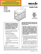
Checking Flame Patterns, Flame Height
Frequency: Periodically.
By: Qualified service technician/Home owner.
Task: Make a visual check of your fireplaces flame patterns.
Make sure the flames are steady - not lifting or floating.
See Figure 17. The flame sensor (DSI) or thermopile/
thermocouple (standing pilot) tips should be covered with
flame. See Figure 8.
Checking Vent System
Frequency: Before initial use and at least annually
thereafter, more frequently if possible.
By: Qualified service technician/Home owner.
Task: Inspect the external vent cap on a regular basis to
ensure that no debris is interfering with the flow of air. Inspect
entire vent system for proper function.
Cleaning Glass Door
Frequency: As necessary
By: Home owner.
Task: Clean as necessary, particularly after adding new ember
(flame colorant) material. Film deposits on the inside of the
glass door should be cleaned off using a household glass
cleaner. NOTE: DO NOT handle or attempt to clean the
door when it is hot and DO NOT use abrasive cleaners.
Figure 17.
Burner Flame Patterns
MAKE SURE THE FLAMES
ARE STEADYNOT
LIFTING OR FLOATING.
6000TVB
7000TV
/