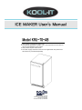
MVP KRU-70-AB User manual
- Category
- Ice cube makers
- Type
- User manual
This manual is also suitable for

Model KRU-70-AB
● This product is designed for indoor use.
● The external appearance, design, color, and components of this machine
may be changed without prior notice.
● This product requires a floor drain.
● The water supply and drain hoses are not supplied with the product and
will need to be purchased separately.
ICE MAKER User's Manual
Toll Free: (888) 275-4538
international: (514) 737-9701
Fax: (514) 342-3854
Toll Free Fax: (877) 453-8832

2
Contents
3~5
4
5
6
7~10
9
10
11
12~13
14
15~17
18~23
24
25
26~27
1. Safety Precautions
- Power supply related items
- Installation related items
2. Part names
3. Installation specifications
- Gravity Drain
4. What to check prior to installation
5. Installation of the Ice Maker
6. Specific Features
7. Guide to Operating the Ice Maker
8. Cleaning the Ice Maker
9. Maintenance of the Ice Maker
10. Specifications
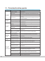
11. Troubleshooting Guide
12. Manufacturer's Warranty

3
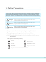
1. Safety Precautions
To prevent any safety-related accidents and to ensure a long and trouble free usage of this
product with better understanding, cautions and warnings are accompanied by symbols
and figures. Make sure you understand the symbols and figures below before proceeding.
※ Injury includes wound or burn that requires l
ong-term outpatient treatment.
※ Property damage means damage or loss of one's house or furniture.
※ Label: If the caution label is damaged, or its text is not legible, contact the customer
service center.
Using the product without taking careful note of this symbol
may cause death or serious injury or fire.
Using the product without taking careful note of this symbol
may cause death or serious injury or fire.
Using the product without taking careful note of this symbol
may cause injury or property damage.
Danger
Warning
Caution
Each figure has the following meaning:
Prohibited
Do not touch!
The power cord must be disconnected from the outlet.
Must be grounded
Disassembly not allowed
Danger of electric shock
Important

4
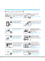
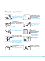
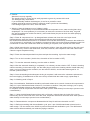
■ Power supply related items ■
Oh! NO
Oh! NO
Avoid putting any object on the
power cord and make sure that
the cord does not get tangled
or tied.
It may cause fire or electric
shock.
Do not touch any electrical
component or the power
cord with wet hands.
It may cause electric shock.
Do not pull the power cord.
Failure to do so may cause
electric shock or fire.
Do not touch the power
cord with wet hands.
Failure to do so may cause
electric shock or fire.
Close the water supply valve
and unplug the product if it is
not going to be used for an
extended period of time.
It may cause electric shock or
fire.
Clean the prongs of the power
plug to remove all substances
including water or dust.
Failure to do so may cause fire
or electric shock.
Stop using the product
if the power cord is
damaged.
It may cause fire or electric
shock.
Do not alter the power cord
or modify it to connect to an
unauthorized power source.
May cause electric shock or
fire.
Do not plug too many
appliances into one
outlet; only one appliance
per outlet is
recommended.
Otherwise, there is danger
of fire.
To replace or repair the
power cord, contact a
professional technician or
our customer service center.
If water has come into
contact with the power
components, immediately
unplug the cord and
completely dry the product
before using it.
Failure to do so may cause
electric shock or fire.
If the power plug or cord
is damaged, do not try to
replace. Contact the
customer service center.
Failure to do so may cause
fire or electric shock.
A/S

5
■ Installation related items ■
THINNER
GAS
GA
SOL
LIN
Keep any heating appliance
away from the power cord.
It may melt the coating of the
cord, causing fire or electric
shock.
Combustible gas or
flammable material (benzene,
gasoline, thinners, LP gas,
etc.) must never be used on
the product.
It may explode or cause fire
or injury.
Do not apply excessive force or
shock to the product.
It may damage the product.
Make sure no water comes
into contact with any electric
part.
If the product has been
immersed in water due to
causes such as flood, be
sure to contact the customer
service center. Otherwise,
the product may short circuit
and cause fire or electric
shock.
Do not disassemble or modify
the product.
It may cause electric shock,
fire, or injury.
Do not install the product
at a place where moisture or
dust gathers easily or where
rain or water splatters.
It may cause electric shock
or fire.
Do not install the product on
an uneven surface.
It may cause injury to the
user or damage to the
product.
The ice maker will operate
efficiently at a room
temperature of
50~100℉ and supplied
water temperature of
between 50℉-90F.
Temperatures outside
these parameters may
damage the product.
Do not store or use
combustible gas or
flammable material near
the product.
It may cause electric shock
or fire.
Contact a professional
service provider to repair
the product.
Incomplete repair may
cause electric shock, fire,
or injury.

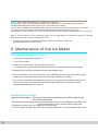
6
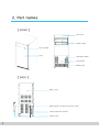
Door handle
Door
Back cover
【 FRONT 】
【 BACK 】
2. Part names
Top cover
Water trough
Operation switch
Front panel
Bottom grill
Water supply connector 3/8" FPT (Inlet)
Drain connector 3/4"FPT
Power cord

7
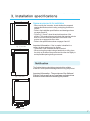
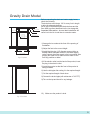
3. Installation specifications
Fig. 1 Front View
Fig. 2 Side View
Fig. 3 Top View
Space requirements for installation
- When moving the ice maker, check whether the prepared
opening dimensions,electric rating, and piping position are
correct.
- Refer to the installation specifications and drawings shown
on pages 9 and 10.
- Figures 4, 5, 6 and 7 show the entire dimensions of the
product. This product has a gravity drain that requires a drain
hose to run from the drain connector at the back of the
product to an appropriate floor drain.
- Refer to the specifications shown on pages 9 and 10.
Important Information :
If the ice maker is installed in
a
corner, the door opening may be limited.
- The bottom of the ice maker should be leveled.
- When moving the product using a hand truck or dolly, place
the dolly on the side of the product and shut the door tightly to
avoid possible opening during movement.
The finished bottom should be protected with a suitable
material to avoid possible damage when moving the product.
Important Information : The provisions of the National
Electric Code as well as any local laws and instructions
should be observed when installing the product.
Notification
857
380
752
850
376
538
98
625
538
37
27.8

8
Requirements for plumbing
The water supply system needs to be installed as follows:
Connect the ice machine to the cold potable water supply using a 1/4" water supply hose with a
3/8"MPT connector. A shut off valve is recommended between the water supply and the ice
maker. If the tap water has a high mineral content(hard water) a water filter is highly
recommended.
The pressure of the tap water should be maintained at a level between 20psi (1.0bar) and 80psi
(4.9bar). The tap water and drain hose should be planned and prepared at the place of installation.
If an electric outlet is available just at the back of the ice maker, installation may be easier.
The electric power, tap water and drain hoses should satisfy all the provisions under the local laws
and regulations. For the position of the tap water, refer to the installation specifications and
drawings on pages 7 and 8.
Important Information :
The product is designed for use in a fixed position. Do not
enclose the
product so that it cannot be moved for service and/or maintenance. When preparing the bottom
after installing the ice maker, place shims equivalent to the thickness of the bottom under the
product to keep the ice maker and bottom horizontal. The lateral side should have at least 1/6" (4)
of space for projection of the screw head.
Important Information :
Piping should be carried out in accordance with all the
provisions
laid out
under the local laws and regulations.

9
Fig. 4 Top View
Fig. 5 Front View
Before connecting the drain and water supply hoses,
check the following:
The drain hose must drop a 1/4" for every foot in length
to allow for adequate draining.
An air gap is required between the drain hose and the
floor drain to prevent backflow into the ice storage bin.
Important Information : Incorect drain installation will
cause ice in the bin to melt due to excessive water.
1)Arrange the ice maker at the front of the opening of
installation.
2)Adjust the feet to the correct height.
3)Install the inlet pipe (1/4" diameter copper tubing or
flexible rubber hose)and connect to the water supply
valve.Connect the water supply to the ice machine after
purging the water line to make sure the water is free
from any particles or debri.
4)If the electric outlet is at the back of the product, insert
the plug in the electric outlet.
5)Install the product so that the front of the product is
facing forwards.
6)Use the inlet pipe after cutting it to the required length.
7)Cut the required length of drain hose.
8)Connect the drain nipple (with a diameter of 3/4” FPT)
9)Turn on the tap and check for any leakage.
10) Make sure the product is level.
Gravity Drain Model
Water Filter
Shut-Off Valve
MIN. 15¼"(387)
24"(610)
0.16(4) 0.16(4)
Drain Tube
Water Inlet Tube
Locate drain
within 2" DIA.
Area 23" back from
front of unit
MIN (857)

10
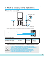
4. What to check prior to installation
■ Follow this process! ■
115V, 60Hz
For your
information
- The water supply valve may have different shapes depending on the installation condition.
- The filter may be located close to the water source or back of the product depending on the situation.
- Be sure to connect the water supply adaptor to the cold water supply.
- The ice maker provides optimal functionality at room temperature of
50~100℉ and supplied water temperature between 50 - 90
o
F.
Water source valve
Water source tube
Drain hose
Connecting water piping
-
Too high temperature of the ice-making water will decrease the amount of ice produced;
too low pressure will prevent ice from being made at all. Install an auxiliary pressure pump
in this case.
- In order to guarantee optimal operation of the product, consult with our
technician on how to install the product. (Contact our authorized technician in
case of moving the product after the initial installation.)
Appropriate water temperature Water pressure
Appropriate
piping / hose size
Ice making water supply 50 ~ 90 ℉
20 ~ 80 psig
3/8" FPT
Ice making water drain - - 3/4" FPT
Avoid uneven surface or any place with too much moisture,direct
sunlight, too much dust, or water splatter.
Water inlet: Ice making water supply 3/8”FPT
Drain connect: 3/4”FPT

11
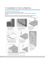
① Loosen the anchor
screws on the lower
hinge of the door
and separate the door.
④ After removing the fixture top
hinge on the right, move it to
the left and fasten the screws
as shown in the above figure.
⑦ After moving the upper door hinge to the left and inserting
it into the hole on the front door, fix it in the hole on the upper
cover and fasten the screws(two parts).
⑧ Check the movement of the door by opening and closing it.
② Loosen the anchor screws
on the lower hinge and
insert the hinge into the hole
on the left.
⑤ Place the upper cover
again and fasten the
screws. (three parts on
the back panel)
③ Release the screws
to remove the upper
door hinge and
upper cover.
⑥ Move the “L” shaped
door hinges of the
upper and lower
parts of the door
to the left.
5. Installation of the Ice Machine
Changing Door-opening Method
The direction in which the door opens can be changed.
The hinges are attached to the right-hand side of the door when the product is shipped from
the factory.
However, the ice maker is designed so that the hinges may be installed on either side. If the
hinges are moved to the holes on the left-hand side, the door will open to the left.
Upper door hinge
Upper door hinge
TOP COVER

12
Installation Checklist
Important Information : The installation technician should check whether any installation
part has been omitted and follow the check list below to ensure safe and proper installation.
If you have any questions or problems regarding installation, address your queries to the
distributor or dealer. You may also seek information on the company’s website.
■ Does the ice maker work properly?
If the ice maker does not work, check whether the plug has been inserted properly.
■ Did you remove all the packing materials and tapes from the inside of the ice maker?
■ Did you observe the instructions on installation?
■ Did you level the unit?
■ Is the front of the kick plate/grill adequately ventilated?
■ Do you sufficiently understand the operation of the ice maker?
■ Be sure to follow any safety instructions for storing or disposing of an old ice maker.
Remove the door or fix the door firmly if the door is closed. If a child gets inside the ice
maker, and the door is closed, they may get injured.
■ Be sure to observe the following:
Since the product makes use of water, proper water supply and draining are required.
■ Be sure to use the product with a properly functioning floor drain to prevent water leaks.
Leaks may cause electric shock due to m oisture, so make sure that the following a re
always observed:
1. When installing the product indoors, be sure to have a floor drain and make the floor
waterproof, especially if the floor can be damaged due to water leaks.
2. A floor drain must be available at the installation site; be sure to connect the drain hose.
3. Make sure that the floor is sloped so that the leaking water drains away even if the drain
hose gets dislodged or damaged. Install a water overflow prevention wall to prevent
damage.
※ The manufacturer will not be liable for any issue arising from failure to comply with the
above mentioned warnings, dislodged / damaged water supply hose, or inappropriate
drainage.
Notification

13
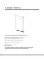
■ The gravity drain naturally drains water and requires a floor drain.
■ A perfect and unified design system with 24.6" of depth.
■ The product supplies good-quality transparent ice.
■ The maximum capacity of the ice container is 26 lb.
■ Automatic ice-removal detection function.
■ Left/Right opening door system.
■ Front ventilation.
■ The product incorporates a magnetic door attachment / detachment structure and
gasket, and an insulator foam system is used for insulating the door.
Fig. 9 Solid figure
6. Specific Features

14
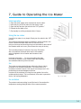
7. Guide to Operating the Ice Maker
Fig. 10 Switch
Fig. 11 Ice cube
Initial operation
① Open the water supply valve connected to the ice maker.
② Insert the plug of the ice maker into the electric outlet.
③ Open the door and turn the switch to the “ICE” position.”
④ Discard the first batch of ice.
⑤ Good quality ice will be produced within1-2 hours.
Using the ice maker
Use of the ice maker is very simple. Simply turn the switch to the “ICE”
position.
The product automatically starts ice production, which continues until
the ice container has been filled with ice. Remove the ice
using an ice scoop and insert the scoop into the holder on the inside of
the container when not in use. (Do not leave the scoop in the ice).
The ice maker produces 24 pieces of ice every 30 minutes.
Also, the produced ice drops down into the ice container;
water is supplied to the ice maker and the water is also
drained.
Important Information : Do not put anything other than
ice in the ice container. Wine or beer bottles are unsanitary
and a detached label may block the drain.
Ice
The ice has a rectangular bell shape (refer to the figure). Newly
produced ice is clear and transparent. The inside of the ice is
sometimes cracked; however, such cracks commonly occur in the
production process and disappear with time.
Ice stored in the container for a long time may gather frost on the
outside and look cloudy. This is normal and, once water is poured on
the ice, the frosting disappears.
Ice container
The product continues making ice until the level of ice reaches the
temperature sensing tube(right side). It then ceases operation.

15
Operation time
It takes about 20-35 minutes to produce a set of 24 ice cubes. The length of one cycle of the ice
maker (ice production and ice harvest) differs depending upon the cleanliness of the ice maker,
the ambient temperature, and the temperature of the water supplied to the ice maker. It takes
about 8-10 hours to fill the empty ice container with ice.
Ice production
The ice production process largely consists of two cycles, ice production and ice harvest. 24
pieces of ice are produced with each cycle of ice production and ice harvest.
When water is sprayed on to the surface of the frozen evaporator, the ice production cycle starts.
Once the ice has formed, the ice harvest cycle starts. The time taken for both cycles together is
about 20-35 minutes.
Ice production cycle
As the ice production cycle progresses, the compressor cycles the refrigerant, the fan motor
circulates the air, and the pump motor circulates water. Once the surface of the evaporator
absorbs the heat from the water, the heat moves to the condenser and with the help of the fan,
the heat is removed . The heat is transferred to the air and the heated air is removed from the ice
maker. At the same time, ice is produced on the surface of the evaporator (at the top of the ice
maker). When the surface of the evaporator has sufficiently cooled, the ice production cycle stops
and ice harvest is started using the program installed in the ice maker.
Ice harvest cycle
The compressor works during the progress of the ice harvest cycle, but the pump and fan
motors are shut off. The hot gas and water supply valves open. When the two valves are
opened and the frozen surfaces are heated, ice drops down into the container.The ice
harvest cycle is now complete and the ice production cycle starts again using the program
installed in the ice maker.
How water is used for ice making
The ice maker starts its work with a fixed quantity of water that has been fed into the water
trough. When water is sprayed onto the surface of the evaporator, the water not containing
mineral impurities freezes and attaches to the evaporator. The water containing impurities drops
down into the water container. During the progress of the ice production cycle, the
mineral impurity level in the water container rises.
During the progress of the ice harvest cycle, water is fed to the ice maker, thereby diluting
the water in the container, and washes a part of the concentrated minerals through the
drain hose.

16
[ Cautions for cleaning the external panels (stainless steel) ]
※ How to remove rust How to clean rusted parts
1. Rust spots in early stage
- Rust spots in early stage mean that the stainless steel itself is not severely affected,
so a mild detergent or any commercially available cleaning agent will restore the original
state. Rust will be removed with ease and at low cost if regular cleaning is done at
appropriate intervals.
2. Red rust
- Rust spots that are not removed after a short period of time will turn into thick reddish
brown rust and will damage the surface of the stainless steel. These are much harder to
remove and the surface will not be fully restored; thus, it is important to remove rust spots
early on.
If commercially available cleaning agents do not work, use sandpaper or a stainless steel
brush to remove the rust before applying the agent for easier removal.
This process requires treatment, such as refurbishment after cleaning.
3. Rust from iron
- Rust from coming into contact with welding spatter, rust from the metal bar above
the stainless steel part, or contact between the stainless steel parts and general metal
parts cause galvanic corrosion. This causes the metal to rust first, and it will eventually
cause the stainless steel to rust if it is not removed. As such, make sure to clean and
remove rust immediately with a mild detergent. However, when the rust has gotten really
bad, it must be removed with 15% nitric acid solution or commercially available stainless
steel cleaner.
4. Rust from exhaust gas or acid rain
- In environments, such as a factory complex or heavy transport sites, the product will
become contaminated in a short amount of time due to exhaust fumes or acid rain and rust
spots will quickly form. Light rust can be washed off with a mild detergent or
soapy water,
but heavy rust will require 15% nitric acid solution or commercially available
stainless steel
cleaner.
5. Rust from salt deposit
- In environments, such as porches of an apartment complex close to the seashore where
the product may be directly exposed to the sea winds, STS304 or STS316 will rust quicker
than normal.These cases require special treatment, such as using painted stainless steel
or regular cleaning.
6. Rusts from disinfectants or cleaning agents
- Sites, such as pools or public baths, that use chlorine-based agents to sterilize the water,
especially those for cleaning bathrooms, contain chlorine content that attaches to and
rusts the stainless steel surface. Thus, it is important to thoroughly wash off such agents
after using them, and a 15% nitric acid solution or commercially available stainless steel
cleaner are required for removing this type of rust.

17
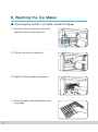
■ Cleaning the nozzle / ice slide / water trough ■
1. Open the door and remove two front
injection bolts on the top cover.
2. Pull the top cover to remove it.
3. Slightly lift the ice slide to remove it.
4. Clean the slide with soft plastic brush
or sponge.
8. Washing the Ice Maker

18
■ Cleaning the filters of the water trough and ice bin
5. Clean the gap of the nozzle frame fixed
on the vessel sheet (water trough).
6. Lift the drain plug inside the vessel sheet
(water trough), clean it, and drain the
water.
* Make sure that the drain plug is assembled
back in the correct position after cleaning;
otherwise, draining will not stop, and the
product will be unable to make ice cubes.
1. Empty the ice bin and prepare a cleaning
solution by distilling 1oz of neutral
dishwashing detergent with 8qts of warm water
(95~115F). Soak a clean cloth in the solution
and clean the inside of the ice bin.
Pour an appropriate amount of the solution
into the drain hose, and then wait until
it dries naturally.
* Press the switch to set it to “Ⅱ”(WASH) when cleaning the product;
this will repeat the process of supplying water for about 2 minutes and operating
the circulation pump 3 times, enabling easier cleaning.
Cleaning the nozzle / ice slide / water trough
- Clean at least once a m
onth after turning off the power.
For your
information

19
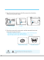
2. Open the front door and remove the filter screens from the bottom
of the ice bin and water trough.
3. Rinse the screens with running water, and then assemble them back
in the water trough and ice bin.
* Otherwise, the water nozzle will get clogged, or debri inside the ice bin
may damage the product by clogging the drain.
* Insert the bottom filter screen first, followed by the top screen.
< Water trough >
< Bottom filter screen > < Top filter screen >
< Ice bin >
Cleaning the filters of the water trough and ice bin
- Cleaning at least once a month after turning off the
power
For your
information

20
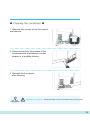
Cleaning the condenser - Cleaning at least once a month after turning off the power
■ Cleaning the condenser ■
2. Remove dust from the surface of the
condenser with a residential vacuum
cleaner or a portable cleaner.
1. Remove two screws on the front panel
and remove.
3. Reinstall the front panel
after cleaning.
For your
information
Page is loading ...
Page is loading ...
Page is loading ...
Page is loading ...
Page is loading ...
Page is loading ...
Page is loading ...
Page is loading ...
-
 1
1
-
 2
2
-
 3
3
-
 4
4
-
 5
5
-
 6
6
-
 7
7
-
 8
8
-
 9
9
-
 10
10
-
 11
11
-
 12
12
-
 13
13
-
 14
14
-
 15
15
-
 16
16
-
 17
17
-
 18
18
-
 19
19
-
 20
20
-
 21
21
-
 22
22
-
 23
23
-
 24
24
-
 25
25
-
 26
26
-
 27
27
-
 28
28


MVP KRU-70-AB User manual
- Category
- Ice cube makers
- Type
- User manual
- This manual is also suitable for
Ask a question and I''ll find the answer in the document
Finding information in a document is now easier with AI


