Maytag MBF1953YEB0 User Instructions

Category
Fridges
Type
User Instructions
THANK YOU for purchasing this high-quality product. If you should experience a problem not covered in TROUBLESHOOTING,
please visit our website at www.maytag.com for additional information. If you still need assistance, call us at 1-800-688-9900.
In Canada, visit our website at www.maytag.ca or call us at 1-800-807-6777.
You will need your model and serial number, located on the inside wall of the refrigerator compartment.
Para obtener acceso a "lnstrucciones para el usuario del refrigerador" en espa_ol, o para obtener informaci6n adicional acerca de
su producto, visite: www.maytag.com.
Necesitara su nQmerode modelo y de serie, ubicado en el interior del compartimiento del refrigerador.
Table of Contents / Table des mati res
REFRIGERATOR SAFETY ........................................................ 1
INSTALLATION INSTRUCTIONS ............................................. 2
REFRIGERATOR USE ............................................................. 11
REFRIGERATOR CARE .......................................................... 15
TROUBLESHOOTING ............................................................. 16
WATER FILTER CERTIFICATIONS ........................................ 18
PERFORMANCE DATA SHEETS ........................................... 19
WAR RANTY ............................................................................. 21
SI_CURITI_ DU RI_FRIGI_RATEUR ......................................... 22
INSTRUCTIONS D'INSTALLATION ....................................... 23
UTILISATION DU REFRIGERATEUR ..................................... 33
ENTRETIEN DU RI:!:FRIGI:!:RATEUR....................................... 37
DEPANNAGE ........................................................................... 38
FEUlLLES DE DONNI:!:ESSUR LA PERFORMANCE ........... 41
GARANTIE ................................................................................ 43
REFRIGERATOR SAFETY
Your safety and the safety of others are very important.
We have provided many important safety messages in this manual and on your appliance. Always read and obey all safety
messages.
This is the safety alert symbol.
This symbol alerts you to potential hazards that can kill or hurt you and others.
All safety messages will follow the safety alert symbol and either the word "DANGER" or "WARNING."
These words mean:
You can be killed or seriously injured if you don't immediately
follow instructions.
You can be killed or seriously injured if you don't follow
instructions.
All safety messages will tell you what the potential hazard is, tell you how to reduce the chance of injury, and tell you what can
happen if the instructions are not followed.
W10366206A
IMPORTANT SAFETY INSTRUCTIONS
WARNING: To reduce the risk of fire, electric shock, or injury when using your refrigerator, follow these basic precautions:
Plug into a grounded 3 prong outlet.
Do not remove ground prong.
Do not use an adapter.
Do not use an extension cord.
Disconnect power before servicing.
Replace all parts and panels before operating.
Remove doors from your old refrigerator.
Use nonflammable cleaner.
Keep flammable materials and vapors, such as gasoline,
away from refrigerator.
Use two or more people to move and install refrigerator.
Disconnect power before installing ice maker (on ice maker
kit ready models only).
Use a sturdy glass when dispensing ice (on some models).
Do not hit the refrigerator glass doors (on some models).
SAVE THESE INSTRUCTIONS
Proper Disposal of Your Old Refrigerator
Suffocation Hazard
Remove doors from your old refrigerator.
Failure to do so can result in death or brain damage.
IMPORTANT: Child entrapment and suffocation are not problems
of the past. Junked or abandoned refrigerators are still dangerous
- even if they will sit for "just a few days." If you are getting rid of
your old refrigerator, please follow these instructions to help
prevent accidents.
Before You Throw Away Your Old Refrigerator or Freezer:
Takeoff the doors.
Leave the shelves in place so that children may not easily
climb inside.
important information to know about disposal of
refrigerants:
Dispose of refrigerator in accordance with Federal and Local
regulations. Refrigerants must be evacuated by a licensed,
EPA certified refrigerant technician in accordance with
established procedures.
INSTALLATION INSTRUCTIONS
Excessive Weight Hazard
Use two or more people to move and install
refrigerator.
Failure to do so can result in back or other injury.
Remove the Packaging
Remove tape and glue residue from surfaces before turning
on the refrigerator. Rub a small amount of liquid dish soap
over the adhesive with your fingers. Wipe with warm water
and dry.
Do not use sharp instruments, rubbing alcohol, flammable
fluids, or abrasive cleaners to remove tape or glue. These
products can damage the surface of your refrigerator. For
more information, see "Refrigerator Safety."
Dispose of/recycle all packaging materials.
When Moving Your Refrigerator:
Your refrigerator is heavy. When moving the refrigerator for
cleaning or service, be sure to cover the floor with
cardboard or hardboard to avoid floor damage. Always pull
the refrigerator straight out when moving it. Do not wiggle or
"walk" the refrigerator when trying to move it, as floor
damage could occur.
2
Clean Before Using
After you remove all of the packaging materials, clean the inside
of your refrigerator before using it. See the cleaning instructions
in "Refrigerator Care."
important information to know about glass shelves
and covers:
Do not clean glass shelves or covers with warm water when
they are cold. Shelves and covers may break if exposed to
sudden temperature changes or impact, such as bumping.
Tempered glass is designed to shatter into many small,
pebble-size pieces. This is normal. Glass shelves and covers
are heavy. Use both hands when removing them to avoid
dropping.
Explosion Hazard
Keep flammable materials and vapors, such as
gasoline, away from refrigerator.
Failure to do so can result in death, explosion, or fire.
To ensure proper ventilation for your refrigerator, allow for 1/2"
(1.25 cm) of space on each side and at the top. Allow for 1"
(2.54 cm) of space behind the refrigerator. If your refrigerator has
an ice maker, allow extra space at the back for the water line
connections. When installing your refrigerator next to a fixed wall,
leave 21/2'' (6.3 cm) minimum on the hinge side (some models
require more) to allow for the door to swing open.
NOTE: This refrigerator is intended for use in a location where the
temperature ranges from a minimum of 55°F (13°C) to a
maximum of 110°F (43°C). The preferred room temperature range
for optimum performance, which reduces electricity usage and
provides superior cooling, is between 60°F (15°C) and 90°F
(32°C). It is recommended that you do not install the refrigerator
near a heat source, such as an oven or radiator.
1/2"(1.25crn)
]1
/
2Y2(63cm)
Electrical Shock Hazard
Plug into a grounded 3 prong outlet.
Do not remove ground prong.
Do not use an adapter.
Do not use an extension cord.
Failure to follow these instructions can result in death,
fire, or electrical shock.
Before you move your refrigerator into its final location, it is
important to make sure you have the proper electrical
connection.
Recommended Grounding Method
A 115 volt, 60 Hz., AC only 15- or 20-amp fused, grounded
electrical supply is required. It is recommended that a separate
circuit serving only your refrigerator be provided. Use an outlet
that cannot be turned off by a switch. Do not use an extension
cord.
NOTE: Before performing any type of installation, cleaning, or
removing a light bulb, turn the refrigerator to OFE Depending on
your model, turn the freezer control to the word OFF, or press the
Freezer down arrow or minus sign touch pad until a dash (-)
appears in both the Freezer and Refrigerator displays as shown.
Disconnect the refrigerator from the electrical source. When you
are finished, reconnect the refrigerator to the electrical source
and reset the temperature controls to the desired setting. See
"Using the Controls."
Gathertherequiredtoolsandpartsbeforestartinginstallation.
Readandfollowtheinstructionsprovidedwithanytoolslisted
here.
TOOLS NEEDED:
Flat-blade screwdriver 1/4"Nut driver
7Ae"and 1/2"Open-end or two 1/4"Drill bit
adjustable wrenches Cordless drill
IMPORTANT:
All installations must meet local plumbing code requirements.
Do not use a piercing-type or 3/le"(4.76 mm) saddle valve
which reduces water flow and clogs more easily.
Use copper tubing and check for leaks. Install copper tubing
only in areas where the household temperatures will remain
above freezing.
For models with water filters, the disposable water filter
should be replaced at least every 6 months.
Water Pressure
A cold water supply with water pressure of between 35 and
120 psi (241 and 827 kPa) is required to operate the water
dispenser and ice maker. If you have questions about your water
pressure, call a licensed, qualified plumber.
Reverse Osmosis Water Supply
IMPORTANT: The pressure of the water supply coming out of a
reverse osmosis system going to the water inlet valve of the
refrigerator needs to be between 35 and 120 psi (241 and
827 kPa).
If a reverse osmosis water filtration system is connected to your
cold water supply, the water pressure to the reverse osmosis
system needs to be a minimum of 40 to 60 psi (276 to 414 kPa).
If the water pressure to the reverse osmosis system is less than
40 to 60 psi (276 to 414 kPa):
Check to see whether the sediment filter in the reverse
osmosis system is blocked. Replace the filter if necessary.
Allow the storage tank on the reverse osmosis system to refill
after heavy usage.
If your refrigerator has a water filter, it may further reduce the
water pressure when used in conjunction with a reverse
osmosis system. Remove the water filter. See "Water
Filtration System."
If you have questions about your water pressure, call a licensed,
qualified plumber.
, J-
Read all directions before you begin.
IMPORTANT: Ifyou turn on the refrigerator before the water line
is connected, turn off the ice maker to avoid excessive noise or
damage to the water valve.
Connect to Water Line
1. Unplug refrigerator or disconnect power.
2. Turn OFF main water supply. Turn ON nearest faucet long
enough to clear line of water.
3. Find a 1/2"to 1W' (12.7 mm to 31.8 mm) vertical cold water
pipe near the refrigerator.
IM PORTANT:
4.
5.
Make sure it is a cold water pipe.
Horizontal pipe will work, but the following procedure
must be followed: Drill on the top side of the pipe, not the
bottom. This will help keep water away from the drill. This
also keeps normal sediment from collecting in the valve.
Determine the length of copper tubing you need. Measure
from the connection on the lower right rear of the refrigerator
to the water pipe. Add 7 ft (2.1 m) to allow for cleaning. Use
1/4"(6.35 mm) O.D. (outside diameter) copper tubing. Be sure
both ends of copper tubing are cut square.
Using a cordless drill, drill a 1/4"hole in the cold water pipe
you have selected.
C
A. Cold waterpipe
B. Pipe clamp
C. Copper tubing
D. Compression nut
D
E
F
G
E.Compression sleeve
F. Shutoff valve
G.Packing nut
6. Fasten the shutoff valve to the cold water pipe with the pipe
clamp. Be sure the outlet end is solidly in the 1/4"drilled hole
in the water pipe and that the washer is under the pipe clamp.
Tighten the packing nut. Tighten the pipe clamp screws
slowly and evenly so the washer makes a watertight seal. Do
not overtighten.
7. Slip the compression sleeve and compression nut on the
copper tubing as shown. Insert the end of the tubing into the
outlet end squarely as far as it will go. Screw compression nut
onto outlet end with adjustable wrench. Do not overtighten or
you may crush the copper tubing.
8. Place the free end of the tubing in a container or sink, and
turn ON the main water supply. Flush the tubing until water is
clear. Turn OFF the shutoff valve on the water pipe.
Connect to Refrigerator
Depending on your model, the water line may come down from
the top or up from the bottom. Follow the connection instructions
for your model.
Style 1
1. Remove plastic cap from water valve inlet port. Attach the
copper tube to the valve inlet using a compression nut and
sleeve as shown. Tighten the compression nut. Do not
overtighten. Confirm copper tubing is secure by pulling on
copper tubing.
2. Create a service loop with the copper tubing. Avoid kinks
when coiling the copper tubing. Secure copper tubing to
refrigerator cabinet with a "P" clamp.
A
C
D
3=
A. Copper tubing
B. "P" clamp
C. Compression nut
D. Compression sleeve
Turn on water supply to refrigerator and check for leaks.
Correct any leaks.
Style 2
1. Create a service loop (minimum diameter of 2 ft [61 cm]) with
the copper tubing. Avoid kinks when coiling the copper
tubing.
2. Remove the plastic cap from water valve inlet port. Place a
compression nut and sleeve on the copper tubing.
3. Insert the end of the copper tubing into the water valve inlet
port. Shape tubing slightly so that the tubing feeds straight
into the port to avoid kinks.
4. Slide the compression nut over the sleeve and screw into the
water valve inlet port.
f ...............................................................
......A
........S
........C
A. Plastic water tubing C. Compression nut
B. Sleeve D. Copper tubing
5=
Using an adjustable wrench, hold the nut on the plastic water
line to keep it from moving. Then, with a second wrench turn
the compression nut on the copper tubing counterclockwise
to completely tighten. Do not overtighten.
9
...........O
A. "P" clamp
B.Plastic water line
C. Compression nut
D. Copper tubing
6. Check connection by pulling on copper tubing. Attach the
plastic water line to the refrigerator cabinet with a "P" clamp.
7. Turn on water supply to the refrigerator and check for leaks.
Correct any leaks.
Complete the Installation
Electrical Shock Hazard
Plug into a grounded 3 prong outlet.
Do not remove ground prong.
Do not use an adapter.
Do not use an extension cord.
Failure to follow these instructions can result in death,
fire, or electrical shock.
1. Plug into a grounded 3 prong outlet.
NOTE: Allow 24 hours to produce the first batch of ice. Discard
the first three batches of ice produced. Allow 3 days to
completely fill the ice storage bin.
TOOLS NEEDED: %e", 3/8",1/4"hex head socket wrench, a Torx®t
T20 screwdriver, a #2 Phillips screwdriver, and a flat-blade
screwdriver.
IMPORTANT:
Your refrigerator may have a standard reversible refrigerator
door with either a freezer door or freezer drawer, or French
doors. Follow the instructions specific to the door style of
your model.
All graphics referenced in the following instructions are
included later in this section after "Final Steps." The graphics
shown for the standard door are for a right-hand swing
refrigerator (hinges factory installed on the right).
If you only want to remove and replace the doors, see
"Remove Door(s) and Hinges" and "Replace Door(s) and
Hinges."
Before you begin, turn the refrigerator control OFF, and
remove food and adjustable door or utility bins from the
doors.
Remove and Replace Refrigerator Door Handles
Standard Door
To remove the handle, remove the screw attaching the trim to
the upper end of the handle. Using a flat-blade screwdriver
wrapped in masking tape, pry the trim piece from the lower
end of the handle. Then, remove the screws attaching the
handle to the door. See Graphic 2.
To replace handle, reverse directions.
French Doors
Style 1 Handles
Using a 3/32"or 1/8"hex key, loosen the two setscrews located
on the side of each handle. Pull the handle straight out from
the door. Make sure you keep the screws for reattaching the
handles. See Style 1 Handle, graphic 1.
To replace the handles, reverse the directions.
Style 2 Handles
To remove the handle, grasp the lower part of the handle
firmly, slide the handle up and pull the handle straight out
from the door. See Style 2 Handle, graphic 1.
To replace the handle, position the handle so that the large
holes in the mounting clips are down and align the holes with
the door studs. Rotate the handle so that the mounting clips
are flat against the door and slide the handle down to
engage. See Style 2 Handle, graphic 1.
Remove Door and Hinges
Standard Door
_" Hex-Head TopHinge Screw
Freezer drawer models
1. Unplug refrigerator or disconnect power.
2. Keep the refrigerator door closed until you are ready to lift it
free from the cabinet.
NOTE: Provide additional support for the door while the
hinges are being moved. Do not depend on the door gasket
magnets to hold the door in place while you are working.
3. Remove the parts for the top hinge as shown in Top Hinge
graphic. Lift the refrigerator door free from the cabinet.
4. Remove the parts for the bottom hinge as shown in Bottom
Hinge graphic.
Freezer door models
1. Unplug refrigerator or disconnect power.
2. Keep the freezer door closed until you are ready to lift it free
from the cabinet.
NOTE: Provide additional support for the door while the
hinges are being moved. Do not depend on the door gasket
magnets to hold the door in place while you are working.
3. Remove the parts for the top hinge as shown in Top Hinge
graphic. Lift the refrigerator door free from the cabinet.
4. Remove the center hinge pin and remove the hinge screws as
shown in the Center Hinge graphic. Lift the freezer door free
from the cabinet.
5. Remove the base grille by grasping the grille firmly with both
hands and pulling it toward you.
6. Remove the parts for the bottom hinge as shown in Bottom
Hinge graphic.
French Doors
Electrical Shock Hazard
Disconnect power before removing doors.
Failure to do so can result in death or electrical shock.
1=
2.
Unplug refrigerator or disconnect power.
Keep the refrigerator doors closed until you are ready to lift
them free from the cabinet.
NOTE: Provide additional support for the refrigerator door
while the hinges are being removed. Do not depend on the
door gasket magnets to hold the door in place while you are
working.
t-@YIOEX is a re,qistered trademark of Saturn Fasteners, Inc.
6
3. Starting with the right-hand side door, remove the parts for
the top hinge as shown in Top Hinge graphic. Lift the
refrigerator door from the bottom hinge pin.
4. Remove the hinge pin cover from the bottom hinge pin and
keep it for later use. See Bottom Hinge graphic.
5. Before removing the left-hand side door, disconnect the
wiring plug located on top of the top hinge by wedging a flat-
blade screwdriver or your fingernail between the two
sections. See Wiring Plug graphic.
NOTE: The green, ground wire remains attached to the hinge.
6. Remove the parts for the left-hand side door top hinge as
shown in the Top Hinge graphic. Lift the door from the bottom
hinge pin.
NOTE: Remove the hinge pin cover from the bottom hinge
pin and keep it for later use. See Bottom Hinge graphic.
Reverse Door - Standard Door (optional)
IMPORTANT: If you want to reverse your door so it opens from
the opposite side, follow these steps. If you are not reversing the
door, see "Replace Door(s) and Hinges."
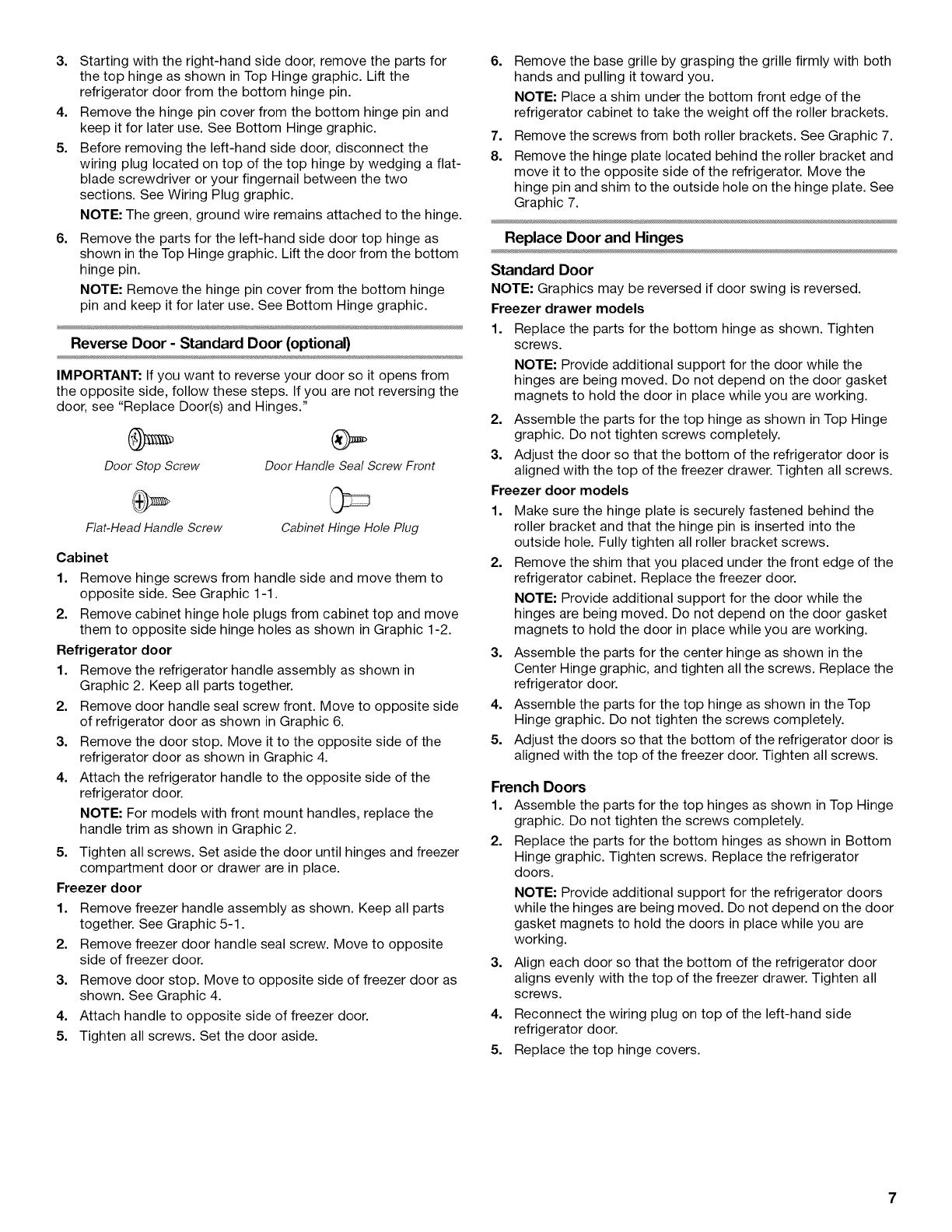
Door StopScrew DoorHandle Seal ScrewFront
Flat-Head Handle Screw Cabinet Hinge HolePlug
Cabinet
1. Remove hinge screws from handle side and move them to
opposite side. See Graphic 1-1.
2. Remove cabinet hinge hole plugs from cabinet top and move
them to opposite side hinge holes as shown in Graphic 1-2.
Refrigerator door
1. Remove the refrigerator handle assembly as shown in
Graphic 2. Keep all parts together.
2. Remove door handle seal screw front. Move to opposite side
of refrigerator door as shown in Graphic 6.
3. Remove the door stop. Move it to the opposite side of the
refrigerator door as shown in Graphic 4.
4. Attach the refrigerator handle to the opposite side of the
refrigerator door.
NOTE: For models with front mount handles, replace the
handle trim as shown in Graphic 2.
5. Tighten all screws. Set aside the door until hinges and freezer
compartment door or drawer are in place.
Freezer door
1. Remove freezer handle assembly as shown. Keep all parts
together. See Graphic 5-1.
2. Remove freezer door handle seal screw. Move to opposite
side of freezer door.
3. Remove door stop. Move to opposite side of freezer door as
shown. See Graphic 4.
4. Attach handle to opposite side of freezer door.
5. Tighten all screws. Set the door aside.
6. Remove the base grille by grasping the grille firmly with both
hands and pulling it toward you.
NOTE: Place a shim under the bottom front edge of the
refrigerator cabinet to take the weight off the roller brackets.
7. Remove the screws from both roller brackets. See Graphic 7.
8. Remove the hinge plate located behind the roller bracket and
move it to the opposite side of the refrigerator. Move the
hinge pin and shim to the outside hole on the hinge plate. See
Graphic 7.
Replace Door and Hinges
Standard Door
NOTE: Graphics may be reversed if door swing is reversed.
Freezer drawer models
1. Replace the parts for the bottom hinge as shown. Tighten
screws.
NOTE: Provide additional support for the door while the
hinges are being moved. Do not depend on the door gasket
magnets to hold the door in place while you are working.
2. Assemble the parts for the top hinge as shown in Top Hinge
graphic. Do not tighten screws completely.
3. Adjust the door so that the bottom of the refrigerator door is
aligned with the top of the freezer drawer. Tighten all screws.
Freezer door models
1. Make sure the hinge plate is securely fastened behind the
roller bracket and that the hinge pin is inserted into the
outside hole. Fully tighten all roller bracket screws.
2. Remove the shim that you placed under the front edge of the
refrigerator cabinet. Replace the freezer door.
NOTE: Provide additional support for the door while the
hinges are being moved. Do not depend on the door gasket
magnets to hold the door in place while you are working.
3. Assemble the parts for the center hinge as shown in the
Center Hinge graphic, and tighten all the screws. Replace the
refrigerator door.
4. Assemble the parts for the top hinge as shown in the Top
Hinge graphic. Do not tighten the screws completely.
5. Adjust the doors so that the bottom of the refrigerator door is
aligned with the top of the freezer door. Tighten all screws.
French Doors
1. Assemble the parts for the top hinges as shown in Top Hinge
graphic. Do not tighten the screws completely.
2. Replace the parts for the bottom hinges as shown in Bottom
Hinge graphic. Tighten screws. Replace the refrigerator
doors.
NOTE: Provide additional support for the refrigerator doors
while the hinges are being moved. Do not depend on the door
gasket magnets to hold the doors in place while you are
working.
3. Align each door so that the bottom of the refrigerator door
aligns evenly with the top of the freezer drawer. Tighten all
screws.
4. Reconnect the wiring plug on top of the left-hand side
refrigerator door.
5. Replace the top hinge covers.
Remove and Replace Freezer Drawer
IMPORTANT:
Two people may be required to remove and replace the
freezer drawer.
All graphics are included later inthis section after "Final
Steps."
Remove and Replace Drawer Handle
Style 1 Handle
Using a 3_32"or 1/8"hex key, loosen the two setscrews located
on the side of each handle. Pull the handle straight out from
the drawer. Make sure you keep the screws for reattaching
the handles. See Style 1 Handle, graphic 2.
To replace the handle, reverse the directions.
Style 2 Handle
To remove the handle, grasp the handle firmly, slide the
handle to the left and pull the handle straight out from the
drawer. See Style 2 Handle, graphic 2.
To replace the handle, position the handle so that the large
holes in the mounting clips are to the right and align the holes
with the door studs. Rotate the handle so that the mounting
clips are flat against the drawer and slide the handle to the
right to engage. See Style 2 Handle, graphic 2.
Remove Drawer Front
1. Open the freezer drawer to full extension.
2. Loosen the four screws attaching the drawer glides to the
drawer front. See Drawer Front Removal graphic.
NOTE: Loosen screws three to four turns. Keep the screws in
the drawer front.
3. Lift drawer front upward and off the screws. See Drawer Front
Removal graphic.
Replace Drawer Front
1. Slide the drawer glides out of the freezer compartment. Insert
the screws in the top of the drawer front into the slots in the
drawer brackets. See Drawer Front Replacement graphic.
2. Pull the drawer brackets toward you to insert the two screws
in the bottom of the drawer front into the brackets. See
Drawer Front Replacement graphic.
3. Completely tighten the four screws.
Final Steps
1. Check all holes to make sure that hole plugs and screws are
in place. Reinstall top hinge cover as shown in Top Hinge
graphic.
Electrical Shock Hazard
Plug into a grounded 3 prong outlet.
Do not remove ground prong.
Do not use an adapter.
Do not use an extension cord.
Failure to follow these instructions can result in death,
fire, or electrical shock.
2. Plug into a grounded 3 prong outlet.
3. Return all removable door parts to door and food to
refrigerator.
8
Standard Door
Door Removal &
Replacement
Top Hinge
c
A. Hinge Cover Screw
B. Top Hinge Cover
C, %_"Hex-Head Hinge Screws
D, Top Hinge
Center Hinge
A
B
C
A, Hinge Pin Cover
B. Center Hinge
C. Hinge Screws
Bottom Hinge
A
B
C
D
E
A. Hinge Pin Shim
B. Bottom Hinge
C. Hinge Plate
D. Roller Bracket
E, _" Hex-Head Hinge Screws
Door Swing Reversal (optional)
A ........................................
C ..................
A, Trim Screw
B, Handle Screws
C. Top Trim
D. Bottom Trim
[]
A ................................................._ v
A. Door Hinge Hole Plug
I
Front View Side View
l;
A B
A. Door Stop Screws
B. Door Stop
A. Flat-Head Handle Screws
/
/
A. Cabinet Hinge Hole Plugs j
L A. _% Hex-Head Hinge Screws I
i
I
!
,oi
J !
Door Handle _a
Seal Screw
Front
Some Standard Door
models have French
Door Style 2 handles.
See French Doors
graphic.
I
A. Door Hinge Hole Plugs I
[]
A. Hinge Pin Shim
B. Bottom Hinge
C. Hinge Plate
D. Roller Bracket
E. _?_"Hex-Head Hinge Screws
French Doors
Electrical Shock Hazard
Disconnect power before removing doors.
Failure to do so can result in death or electrical shock.
Top Hinges
t
A, Hinge Cover Screw
B, Top Hinge Cover
C, s/18" Hex Head Hinge Screws
D. Top Hinge
Bottom Hinges
A. Hinge Pin Cover
B, Bottom Hinge
C. Hinge Screws
Wiring Plug
B
C
Style 1 - Handle
\
\
A. 3/32"or _" Setscrew
Style 1 - Handle @
J
A
3 1
A, _2" or _" Setscrew
ii
i
i
i!
ii
i
11
ii
/
/
i I
I
i
i !
i1
\
\
\
\
\
\
\
Style 2 - Handle
Style 2 - Handle
A. Loosen 4 Door Bracket Screws
10
The base grille covers the leveling screws and roller assemblies
located at the bottom of the refrigerator cabinet below the freezer
door or drawer. Before making adjustments, remove the base
grille and move the refrigerator to its final location.
1. Remove the base grille. Grasp the grille firmly and pull it
toward you.
2.
3.
4.
5.
Move the refrigerator to its final location.
NOTE: To allow the refrigerator to roll easier, raise the leveling
legs off the floor by turning the leveling screws
counterclockwise. The front rollers will be touching the floor.
So the doors will close easier, use a V4"hex driver to turn both
leveling screws clockwise. This will raise the front of the
refrigerator tilting it slightly downward to the rear. Turn both
leveling screws the same amount.
NOTE: Having someone push against the top of the
refrigerator takes some weight off the leveling screws. This
makes it easier to turn the screws.
..........A
A. Leveling screw
Open and close the doors to make sure they close as easily
as you like. If not, increase the tilt by turning both leveling
screws clockwise. It may take several turns of the leveling
screw to allow the doors to close easier.
Check for door alignment. If one door is lower than the other,
adjust the leveling screw, on the lower side of the refrigerator.
Using a V4"hex driver, turn the screw clockwise to raise that
side of the refrigerator until the doors are aligned. It may take
several turns of the leveling screw to raise the refrigerator.
NOTE: Having someone push against the top of the
refrigerator takes some weight off the leveling screws. This
makes it easier to turn the screws.
6.
Make sure the refrigerator is steady. If the refrigerator seems
unsteady or rolls forward when the door or drawer is opened
adjust the leveling screws. Using a V4"hex driver, turn the
leveling screw on each side clockwise until the rollers are up
and the leveling feet are firmly against the floor.
NOTE: Having someone push against the top of the
refrigerator takes some weight off the leveling screws. This
makes it easier to turn the screws.
7. Replace the base grille by aligning the ends of the grille with
the leveling assemblies on each side and snapping the grille
into place.
_/##############################H______
REFRIGERATOR USE
There are two refrigerator compartment doors. The doors can be
opened and closed either separately or together.
There is a vertically-hinged seal on the left refrigerator door.
When the left side door is opened, the hinged seal
automatically folds inward so that it is out of the way.
When both doors are closed, the hinged seal automatically
forms a seal between the two doors.
A
A. Hinged seal
11
Your model may have either Electronic or Digital Controls.
IMPORTANT:
Wait 24 hours for your refrigerator to cool completely before
adding food. If you add food before the refrigerator has
cooled completely, your food may spoil.
NOTE: Adjusting the Refrigerator and Freezer Controls to a
higher (colder) than recommended setting will not cool the
compartments any faster.
The recommended settings should be correct for normal
household refrigerator use. The controls are set correctly
when milk or juice is as cold as you like and when ice cream
is firm.
If the temperature is too warm or too cold in the refrigerator or
freezer, first check the air vents to be sure they are not
blocked before adjusting the controls.
I!!!ectron c Cont o
For your convenience, the temperature controls are preset at the
factory. When you first install your refrigerator, make sure the
controls are still set to the recommended setting as shown.
Style 1
Recommended Setting "4"
electronic dual cool
freezer scroll down for cooling off refrigerator
7 iscoldest recem mended setting 4 7 Js coldest
..... J
Style 2
Recommended Setting "4"
To Turn Off/On:
Style 1-Press the freezer minus sign touch pad until a
dash (-) appears in both the refrigerator and freezer displays.
Neither compartment will cool.
Style 2-Press the freezer down arrow touch pad until a
dash (-) appears in both the refrigerator and freezer displays.
Neither compartment will cool.
Humidity Control (on some models)
The humidity control turns on a heater to help reduce moisture on
the door hinge seal. Use in humid environments or when you
notice moisture on the door hinge seal. The refrigerator uses
more energy when Humidity Control is on.
Press the control to ON when the environment is warm and
more humid, or if you notice moisture on the door hinge seal.
Press the control to OFF to save energy when the
environment is less humid.
HumidityControl
On Off
Adjusting Controls
If you need to adjust the temperature in either the refrigerator or
freezer compartment, use the settings listed in the chart below as
a guide.
To adjust the temperature:
Style 1-Press the up or down arrow touch pads
Style 2-Press the plus or minus sign touch pads.
Except when first turning on the refrigerator, do not adjust the
control more than one setting at a time. Wait 24 hours between
adjustments for the temperature to stabilize.
CONDITION/REASON: ADJUSTMENT:
REFRIGERATOR too warm REFRIGERATOR
Control one setting
higher
FREEZER too warm/too little ice FREEZER Control one
setting higher
REFRIGERATOR too cold REFRIGERATOR
Control one setting
lower
FREEZER too cold FREEZER Control one
setting lower
i_ ¸ _ _i_,_ _
For your convenience, your temperature controls are preset at
the factory. When you first install your refrigerator, make sure the
controls are still set to the Initial settings as shown.
Initial Settings
L . Freezer Refrigerator .....................f
IMPORTANT: When the power is on, the temperature display
shows the set point temperature of the compartment.
To Turn Your Refrigerator Off/On:
Press both the freezer and refrigerator (+) touch pads
repeatedly until "OFF" appears in the displays. Allow a few
seconds for the refrigerator to shut off. Neither compartment
will cool.
Press both the refrigerator and freezer (-) touch pads to turn
on the refrigerator.
Adjusting Digital Controls
The REFRIGERATOR control adjusts the refrigerator
compartment temperature. The FREEZER control adjusts the
freezer compartment temperature.
If you need to adjust the temperature in either the refrigerator or
freezer compartment, use the settings listed in the chart as a
guide.
12
To Adjust Set Point Temperatures:
The first touch of the (+) or (-) touch pad displays the current
temperature set point.
Press the (+) or (-) touch pads until the desired temperature
set point is displayed.
NOTE: Except when first turning on the refrigerator, do not
adjust either temperature control more than one setting at a
time. Wait 24 hours between adjustments for the temperature
to stabilize.
CONDITION/REASON: ADJUSTMENT:
REFRIGERATOR too warm Adjust REFRIGERATOR
Control lower
FREEZER too warm/too little ice Adjust FREEZER
Control lower
REFRIGERATOR too cold Adjust REFRIGERATOR
Control higher
FREEZER too cold Adjust FREEZER
Control higher
Additional Digital Control Center Features
Fast Cool
The Fast Cool feature assists with periods of high refrigerator
use, full grocery loads, or temporarily warm room temperatures.
Press the Fast Cool touch pad to set the freezer and
refrigerator to the lowest temperature settings. Press the Fast
Cool touch pad again to return to the normal refrigerator set
point.
NOTE: The Fast Cool feature will automatically shut off in
approximately 12 hours.
o
Fast Ice
The Fast Ice feature assists with temporary periods of heavy ice
use by increasing ice production.
Press the Fast Ice touch pad to set the freezer to the lowest
temperature setting. Press the Fast Ice touch pad again to
return to the normal freezer set point.
NOTE: When Fast Ice is on, the (+) and (-) pads for the freezer
control will not operate. The Fast Ice feature will automatically
shut off in approximately 24 hours.
o
Temp Alarm
The Temp Alarm feature provides temperature information in the
event of a power outage.
Power outage: During a power outage, if the temperatures in the
refrigerator and freezer compartments exceed normal operating
temperatures, the highest temperature reached will be displayed.
Press the Temp Alarm touch pad until the indicator light is lit,
to turn on this feature. Press and hold Temp Alarm for
3 seconds until the indicator light goes off to turn off this
feature.
Temperature alarm: An alarm will sound repeatedly if the freezer
or refrigerator compartment temperatures exceed normal
operating temperatures for an hour or more.
The temperature displays will alternately show the current
temperatures and the highest temperatures the compartments
reached.
Press the Temp Alarm touch pad once to stop the audible
alarm and alternating temperature displays. The Temp Alarm
light will continue to flash until the refrigerator returns to the
set temperature.
o
Door Alarm
The Door Alarm feature sounds a chime every few seconds when
the refrigerator door has been left open for 5 continuous minutes.
The chime will sound until the door is closed or Door Alarm is
turned off.
Press the Door Alarm touch pad to turn this feature on or off.
The indicator light will be lit when the Door Alarm feature
is on.
o
Reset Filter
The Reset Filter control allows you to restart the water filter status
tracking feature each time you replace your water filter. See
"Water Filtration System."
Press and hold the Reset Filter touch pad for 3 seconds, until
the Order or Replace light turns off.
Order Replace
O O
Press and hold 3 sec to
reset water filter lig,ht
Digital Control User Preferences
The control center allows you to set user preferences, if desired.
Super Cool (CC)
This preference allows you to improve the air flow and
temperature control. To save energy, turn off this feature by
pressing OFR
Temperature Display (F_C)
This preference allows you to change the temperature display.
F - Temperature in degrees Fahrenheit
C - Temperature in degrees Celsius
Alarm (AL)
This preference allows you to turn off the sound of all alarms.
ON - You will hear the alarm sound.
OFF - You will not hear the alarm sound.
13
Auto Light Level Selection (LL)
This preference allows you to adjust the dispenser light level from
dimmest to brightest (settings 1 through 9).
NOTE: The Auto Light feature on the control center must be
selected to activate this preference.
Sabbath Mode (SAB)
ON - All control panel lights and alarm tones will be disabled.
OFF - All control panel lights and alarm tones will be enabled.
NOTE: Press the Door Alarm touch pad for 3 seconds to restore
all lights.
To Access the User Preferences Menu:
1. Press and hold the Door Alarm touch pad for 3 seconds. The
preference name will appear in the Freezer display and the
preference status (F or C) or (ON or OFF) will appear in the
Refrigerator display.
2. Use the Freezer (+) or (-) touch pads to scroll through the
preference names. When the desired preference name is
displayed, press the Refrigerator (+) or (-) touch pads to
change the preference status.
3. Set your preferences by pressing and holding the Door Alarm
touch pad for 3 seconds, or by shutting the refrigerator
compartment door.
You can control the amount of humidity in the moisture-sealed
crisper. Depending on your model, adjust the control to any
setting between FRUIT and VEGETABLES or LOW and HIGH.
FRUIT/LOW (open) for best storage of fruits and vegetables with
skins.
VEGETABLES/HIGH (closed) for best storage of fresh, leafy
vegetables.
o_ _'odc s
IMPORTANT: Flush the water system before turning on the ice
maker, See "Water Dispenser,"
Turning the Ice Maker On/Off
To turn the ice maker ON, simply lower the wire shutoff arm.
To manually turn the ice maker OFF, lift the wire shutoff arm to the
OFF (arm up) position and listen for the click.
NOTE: Your ice maker has an automatic shutoff. As ice is made,
the ice cubes will fill the ice storage bin and the ice cubes will
raise the wire shutoff arm to the OFF (arm up) position. Do not
force the wire shutoff arm up or down.
NOTE: Turn off the ice maker before removing the ice storage bin
to serve ice or to clean the bin. This will keep the ice cubes from
dropping out of the ice maker and into the freezer compartment.
After replacing the ice storage bin, turn on the ice maker.
Ice Production Rate
The ice maker should produce a complete batch of ice
approximately every 3 hours.
To increase ice production, lower the freezer and refrigerator
temperature. See "Using the Controls." Wait 24 hours
between adjustments.
Remember
Allow 24 hours to produce the first batch of ice. Allow 3 days
to completely fill the ice storage bin. Discard the first three
batches of ice produced.
The quality of your ice will be only as good as the quality of
the water supplied to your ice maker. Avoid connecting the
ice maker to a softened water supply. Water softener
chemicals (such as salt) can damage parts of the ice maker
and lead to poor quality ice. If a softened water supply cannot
be avoided, make sure the water softener is operating
properly and is well maintained.
Do not store anything on top of the ice maker or in the ice
storage bin.
IM PORTANT:
After connecting the refrigerator to a water source or
replacing the water filter, flush the water system. Use a sturdy
container to depress and hold the water dispenser lever for
5 seconds, then release it for 5 seconds. Repeat until water
begins to flow. Once water begins to flow, continue
depressing and releasing the dispenser lever (5 seconds on,
5 seconds off) until a total of 4 gal. (15 L) has been
dispensed. This will flush air from the filter and water
dispensing system, and prepare the water filter for use.
Additional flushing may be required in some households. As
air is cleared from the system, water may spurt out of the
dispenser.
NOTE: After 5 minutes of continuous dispensing, the
dispenser will stop dispensing water to avoid flooding. To
continue dispensing, press the dispenser button again.
Allow 24 hours for the refrigerator to cool down and chill
water. Dispense enough water every week to maintain a fresh
supply.
14
Dispensing Water
1. Hold a container under the dispenser while pressing the
button.
2. Release the button to stop dispensing.
Replacing the Water Filter
To purchase a replacement water filter, model UKF8001AXX-750
or UKF8001AXX-200, contact your dealer or call 1-800-688-9900
U.S.A. or 1-800-807-6777 Canada.
IMPORTANT: Air trapped in the water system may cause water
and filter to eject. Always dispense water for at least 2 minutes
before removing the filter or blue bypass cap.
1. Turn filter counterclockwise to remove.
2. Remove sealing label from replacement filter and insert the
filter end into the filter head.
3. Turn the filter clockwise until it stops. Snap the filter cover
closed.
4. Flush the water system. See "Water Dispenser" or "Water and
Ice Dispenser."
NOTE: The dispenser feature may be used without a water filter
installed. Your water will not be filtered. If this option is chosen,
replace the filter with the blue bypass cap.
REFRIGERATOR CARE
The water filter is located in the upper right-hand corner of the
refrigerator compartment.
Do not use with water that is microbiologically unsafe or
of unknown quality without adequate disinfection before
or after the system. Systems certified for cyst reduction
may be used on disinfected waters that may contain
filterable cysts.
Water Filter Status Lights
When a water filter has been installed in the refrigerator the water
filter status lights will remind you when it is time to order and
replace your water filter.
The Order light (yellow) will illuminate when 90% of the
volume of water for which the filter is rated has passed
through the filter OR 5 months have passed since the filter
was installed.
The Replace light (red) will illuminate when the rated volume
of water has passed through the filter OR 6 months have
passed since the filter was installed. A new water filter should
be installed immediately when the Replace light is
illuminated.
The disposable water filter should be replaced at least every
6 months OR earlier if the flow of water to your water dispenser
or ice maker decreases noticeably.
Reset Water Filter Status
After replacing the water filter, press and hold Reset Filter or Filter
Reset (depending on your model) for 3 seconds. The Order and
Replace indicator lights will blink and then go off when the
system is reset. See "Using the Controls."
Explosion Hazard
Use nonflammable cleaner.
Failure to do so can result in death, explosion, or fire.
Both the refrigerator and freezer sections defrost automatically.
However, clean both sections about once a month to avoid
buildup of odors. Wipe up spills immediately.
IM PC RTANT:
Because air circulates between both sections, any odors
formed in one section will transfer to the other. You must
thoroughly clean both sections to eliminate odors. To avoid
odor transfer and drying out of food, wrap or cover foods
tightly.
For stainless steel models, stainless steel is corrosion-
resistant and not corrosion-proof. To help avoid corrosion of
your stainless steel, keep your surfaces clean by using the
following cleaning instructions.
To Clean Your Refrigerator:
NOTE: Do not use abrasive or harsh cleaners such as window
sprays, scouring cleansers, flammable fluids, muriatic acid,
cleaning waxes, concentrated detergents, bleaches or cleansers
containing petroleum products on exterior surfaces (doors and
cabinet), plastic parts, interior and door liners or gaskets. Do not
use paper towels, scouring pads, or other harsh cleaning tools.
1. Unplug refrigerator or disconnect power.
2. Hand wash, rinse, and dry removable parts and interior
surfaces thoroughly. Use a clean sponge or soft cloth and a
mild detergent in warm water.
15
3. Clean the exterior surfaces.
Painted metal: Wash painted metal exteriors with a clean,
soft cloth or sponge and a mild detergent in warm water.
Rinse surfaces with clean, warm water and dry immediately
to avoid water spots.
Stainless steel: Wash stainless steel surfaces with a clean,
soft cloth or sponge and a mild detergent in warm water.
Rinse surfaces with clean, warm water and dry immediately
to avoid water spots.
NOTE: When cleaning stainless steel, always wipe in the
direction of the grain to avoid cross-grain scratching.
4. There is no need for routine condenser cleaning in normal
home operating environments. If the environment is
particularly greasy or dusty, or there is significant pet traffic in
the home, the condenser should be cleaned every 2 to
3 months to ensure maximum efficiency.
If you need to clean the condenser:
Remove the base grille.
Use a vacuum cleaner with a soft brush to clean the grille,
the open areas behind the grille and the front surface area
of the condenser.
5.
Replace the base grille when finished.
Plug in refrigerator or reconnect power.
.............. *' .... t _,,_
_?
NOTE: Not all appliance bulbs will fit your refrigerator. Be sure to
replace the bulb with an appliance bulb of the same size, shape,
and wattage (no greater than 40 watts).
1. Unplug the refrigerator or disconnect power.
2. Remove the light shield (on some models).
Top of the refrigerator compartment - Slide the light shield
toward the back of the compartment to release it from the
light assembly.
3. Replace the burned-out bulb(s) with an appliance bulb(s) no
greater than 40 watts.
4. Replace the light shield.
5. Plug in refrigerator or reconnect power.
TROUBLESHOOTING
First try the solutions suggested here or visit our website and reference FAQs (Frequently Asked Questions)
to possibly avoid the cost of a service call.
In the U.S.A., www.maytag.com In Canada, www.maytag.ca
Are controls on? Make sure the refrigerator controls are on.
The refrigerator will not operate See "Using the Control(s)."
Electrical Shock Hazard
Plug into a grounded 3 prong outlet.
Do not remove ground prong.
Do not use an adapter.
Do not use an extension cord.
Failure to follow these instructions can result in death,
fire, or electrical shock.
Power cord unplugged? Plug into a grounded 3 prong
outlet.
Is outlet working? Plug in a lamp to see if the outlet is
working.
Household fuse blown or circuit breaker tripped? Replace
the fuse or reset the circuit breaker. If the problem continues,
call an electrician.
New installation? Allow 24 hours following installation for the
refrigerator to cool completely.
NOTE: Adjusting the temperature controls to coldest setting
will not cool either compartment more quickly.
The motor seems to run too much
Your new refrigerator may run longer than your old one due to its
high-efficiency compressor and fans. The unit may run even
longer if the room is warm, a large food load is added, doors are
opened often, or if the doors have been left open.
The refrigerator seems noisy
Refrigerator noise has been reduced over the years. Due to this
reduction, you may hear intermittent noises from your new
refrigerator that you did not notice from your old model. Below
are listed some normal sounds with explanations.
Buzzing - heard when the water valve opens to fill the ice
maker
Pulsating - fans/compressor adjusting to optimize
performance
Hissing/Rattling - flow of refrigerant, movement of water
lines, or from items placed on top of the refrigerator
16
Sizzling/Gurgling - water dripping on the heater during
defrost cycle
Popping - contraction/expansion of inside walls, especially
during initial cool-down
Water running - may be heard when ice melts during the
defrost cycle and water runs into the drain pan
Creaking/Cracking - occurs as ice is being ejected from the
ice maker mold.
The doors will not close completely
Door blocked open? Move food packages away from door.
Bin or shelf in the way? Push bin or shelf back in the correct
position.
The doors are difficult to open
Explosion Hazard
Use nonflammable cleaner.
Failure to do so can result in death, explosion, or fire.
Gaskets dirty or sticky? Clean gaskets and contact surfaces
with mild soap and warm water. Rinse and dry with soft cloth.
/;
Temperature is too warm
New installation? Allow 24 hours following installation for the
refrigerator to cool completely.
Door(s) opened often or left open? Allows warm air to enter
refrigerator. Minimize door openings and keep doors fully
closed.
Large load of food added? Allow several hours for
refrigerator to return to normal temperature.
Controls set correctly for the surrounding conditions?
Adjust the controls a setting colder. Check temperature in
24 hours. See "Using the Control(s)."
There is interior moisture buildup
NOTE: Some moisture buildup is normal.
Humid room? Contributes to moisture buildup.
Door(s) opened often or left open? Allows humid air to
enter refrigerator. Minimize door openings and keep doors
fully closed.
The ice maker is not producing ice or not enough ice
Refrigerator connected to a water supply and the supply
shutoff valve turned on? Connect refrigerator to water
supply and turn water shutoff valve fully open.
Kink in the water source line? A kink in the line can reduce
water flow. Straighten the water source line.
Ice maker turned on? Make sure wire shutoff arm or switch
(depending on model) is in the ON position.
New installation? Wait 24 hours after ice maker installation
for ice production to begin. Wait 72 hours for full ice
production.
Freezer door closed completely? Firmly close the freezer
compartment door. If the freezer compartment door will not
close all the way, see "The doors will not close completely,"
earlier in this section.
Large amount of ice recently removed? Allow 24 hours for
ice maker to produce more ice.
Ice cube jammed in the ice maker ejector arm?
Remove ice from the ejector arm with a plastic utensil.
Water filter installed on the refrigerator? Remove filter and
operate ice maker. If ice volume improves, then the filter may
be clogged or incorrectly installed. Replace filter or reinstall it
correctly.
Reverse osmosis water filtration system connected to
your cold water supply? This can decrease water pressure.
See "Water Supply Requirements."
The ice cubes are hollow or small
NOTE: This is an indication of low water pressure.
Water shutoff valve not fully open? Turn the water shutoff
valve fully open.
Kink in the water source line? A kink in the line can reduce
water flow. Straighten the water source line.
Water filter installed on the refrigerator? Remove filter and
operate ice maker. If ice quality improves, then the filter may
be clogged or incorrectly installed. Replace filter or reinstall it
correctly.
Reverse osmosis water filtration system connected to
your cold water supply? This can decrease water pressure.
See "Water Supply Requirements."
Questions remain regarding water pressure? Call a
licensed, qualified plumber.
Off-taste, odor or gray color in the ice
New plumbing connections? New plumbing connections
can cause discolored or off-flavored ice.
Ice stored too long? Discard ice. Wash ice bin. Allow
24 hours for ice maker to make new ice.
Odor transfer from food? Use airtight, moisture proof
packaging to store food.
17
Are there minerals (such as sulfur) in the water? A water
filter may need to be installed to remove the minerals.
Water filter installed on the refrigerator? Gray or dark
discoloration in ice indicates that the water filtration system
needs additional flushing. Flush the water system before
using a new water filter. Replace water filter when indicated.
See "Water Filtration System."
The water dispenser will not operate properly
Refrigerator connected to a water supply and the supply
shutoff valve turned on? Connect refrigerator to water
supply and turn water shutoff valve fully open.
Kink in the water source line? Straighten the water source
line.
New installation? Flush and fill the water system. See "Water
Dispenser."
Is the water pressure at least 35 psi (241 kPa)? The water
pressure to the home determines the flow from the dispenser.
See "Water Supply Requirements."
Water filter installed on the refrigerator? Remove filter and
operate dispenser. If water flow increases, the filter may be
clogged or incorrectly installed. Replace filter or reinstall it
correctly.
Refrigerator door closed completely? Close the door
firmly. If it does not close completely, see "The doors will not
close completely," earlier in this section.
Recently removed the doors? Make sure the water
dispenser wire/tube assembly has been properly
reconnected. See "Refrigerator Door(s) and Drawer."
Reverse osmosis water filtration system connected to
your cold water supply? This can decrease water pressure.
See "Water Supply Requirements."
Water is leaking from the dispenser system
NOTE: One or two drops of water after dispensing is normal.
Glass not being held under the dispenser long enough?
Hold the glass under the dispenser 2 to 3 seconds after
releasing the dispenser lever.
New installation? Flush the water system. See "Water
Dispenser."
Recently changed water filter? Flush the water system. See
"Water Dispenser."
Water on the floor near the base grille? Make sure the
water dispenser tube connections are fully tightened. See
"Refrigerator Door(s) and Drawer."
Water from the dispenser is warm
NOTE: Water from the dispenser is only chilled to 50°F (10°C).
New installation? Allow 24 hours after installation for the
water supply to cool completely.
Recently dispensed large amount of water? Allow
24 hours for water supply to cool completely.
Water not been recently dispensed? The first glass of water
may not be cool. Discard the first glass of water.
Refrigerator connected to a cold water pipe? Make sure
the refrigerator is connected to a cold water pipe. See "Water
Supply Requirements."
WATER FILTER
CERTIFICATIONS
State of California
Department of PuNic Health
WaterTreatmentDevice
CertificateNumber
03- 1583
Date Issued: September 16, 2008
Date Revised: April 22, 2009
Trademark/Model Desienation Replacement Elements
UKI_8001ANX-75(
Manulacturer: Cuno Im
The water treatment devie_tsj li_ted on this certificate have met the t_sting requi_eme01s pursuant to Section
116830 of the Health and S_af_ty Code for the follo_vimt health related egnjtarllinants:
Microbiolo ical C_Pa_ninants and Turbidlt_ Confaminants
Cysts _gb_stos
Turbidily 5 be,_d
Organic Contalnbl_lltts
Atrazinc
I.mdane
Benzene
Carbofuran
p-dlchlorobenzene
'l'oxaphene
Tetrachloroelhylene
Rated Service Capacity: 750 gal. Rated Service Flow: 0.78 gpm
Conditions of Certification:
DO not use where wamr is microbiologicaIIy unsafe or with wamr of unknown quality except tha_ systems certified
fbr cyst reduction may be used on disinlhcted waters that may contaill I_l_erable cysts,
State of California
Department of Public Health
WaterTreatmentDevice
CertificateNumber
09- 1979
Date Issued: May 8, 2009
Date Revised: 6/22/2010
Trademark/Model Designation
UKF8001 AXX-200
Manut_cturer:
116830 ofthe
Cysts
Turbidity I
Alrazine
Benzene
Carbofllra_
Chlorobenzene
Endrin
Replacenlent Elements
UKF800t
46 9006
certified for cyst reduction may be used 6o di_Ipfected _at¢_S that raa_, co0tain filterable cysts.
18
PERFORMANCE DATA SHEETS
Interior Water Filtration System
Model UKF8001AXX-750 Capacity 750 Gallons (2839 Liters)
System tested and certified by NSF International against NSF/ANSI Standard 42 for the
reduction of Chlorine Taste and Odor, Particulate Class I*; and against NSF/ANSI
Standard 53 for the reduction of Lead, Mercury, Atrazine, Benzene, p-Dichlorobenzene,
Carbofuran, Toxaphene, Cysts, Turbidity, Asbestos, Tetrachloroethylene and Lindane.
This system has been tested according to NSF/ANSI Standards 42 and 53 for the reduction of the substances listed below. The
concentration of the indicated substances in water entering the system was reduced to a concentration less than or equal to the
permissible limit for water leaving the system, as specified in NSF/ANSI Standards 42 and 53.
Substance Reduction NSF Reduction Average Influent Challenge Maximum Average Minimum% Average%
Aesthetic Effects Requirements Influent Concentration Effluent Effluent Reduction Reduction
Chlorine Taste/Odor 50% reduction 2.00 mg/L 2.0 mg/L + 10% 0.06 mg/L ** 0.050625 mg/L 97.00% 97.52%
Particulate Class I* 85% reduction 14,000,000 #/mL Atparticles/mLleast10,000 370,000 #/mL 196,666 #/mL 97.40% 99.00%
Contaminant NSF Reduction Average Influent Challenge Maximum Average Minimum% Average%
Reduction Requirements Influent Concentration Effluent Effluent Reduction Reduction
Lead: @ pH 6.5 0.010 mg/L 0.150 mg/U 0.15 mg/L + 10% < 0.001 mg/L < 0.001 mg/L >99.30% >99.30%
Lead: @ pH 8.5 0.010 mg/L 0.150 mg/12 0.15 mg/L _+10% < 0.001 mg/L < 0.001 mg/L >99.30% >99.30%
Mercury: @ pH 6.5 0.002 mg/L 0.006 mg/L 0.006 mg/L + 10% 0.0005 mg/L 0.0003 mg/L 91.70% 95.00%
Mercury: @ pH 8.5 0.002 mg/L 0.0059 mg/L 0.006 mg/L _+10% 0.0018 mg/L 0.00073 mg/L 69.20% 88.10%
Benzene 0.005 mg/L 0.0133 mg/L 0.015 mg/L _+10% 0.0005 mg/L 0.0005 mg/L 96.10% 96.30%
p-Dichlorobenzene 0.075 mg/L 0.210 mg/L 0.225 mg/L _+10% < 0.0005 mg/L < 0.0005 mg/L >99.80% >99.80%
Carbofuran 0.040 mg/L 0.0753 mg/L 0.08 mg/L _+10% 0.027 mg/L 0.008 mg/L 64.60% 73.45%
Toxaphene 0.003 mg/L 0.015 mg/L 0.015 _+10% < 0.001 mg/L < 0.001 mg/L >93.3% >93.3%
Atrazine 0.003 mg/L 0.0102 mg/L 0.009 mg/L _+10% 0.0027 mg/L 0.00105 mg/L 76.30% 89.40%
Asbestos >99% 126.5 MF/L 107to 108fibers/L tt < 0.17 MF/L < 0.17 MF/L >99.99% >99.99%
Live Cysts _ >99.95% 122,500 #/L 50,000/L min. < 1 #/U < 1 #/U >99.99% >99.99%
Turbidity 0.5 NTU 10.5 NTU 11 _+1 NTU 0.30 NTU 0.125 NTU 97.30% 98.80%
Lindane 0.0002 mg/L 0.0019 mg/L 0.002 _+10% < 0.00016 mg/L 0.000035 mg/L 91.80% 97.90%
Tetrachloroethylene 0.005 mg/L 0.015 mg/L 0.015 mg/L _+10% < 0.0005 mg/L < 0.0005 mg/L >96.6% >96.6%
Test Parameters: pH = 7.5 _+0.5 unless otherwise noted. Flow = 0.78 gpm (2.9 Lpm). Pressure =
(20°0 _+3°0).
It is essential that operational, maintenance, and filter
replacement requirements be carried out for the product to
perform as advertised.
The disposable water filter should be replaced at least every
6 months.
The filter monitor system measures the amount of water that
passes through the filter and alerts you to replace the filter.
When 90% of the filter's rated life is used, the yellow (Order)
light comes on. When 100% of the filter's rated life is used,
the red (Replace) light comes on, and it is recommended that
you replace the filter. For models without filter status lights,
replace the filter every 6 months. Use replacement filter
model UKF8001AXX-750. 2011 suggested retail price of
$44.99 U.S.A./S49.95 Canada. Prices are subject to change
without notice.
The product is for cold water use only.
Do not use with water that is microbiologically unsafe or of
unknown quality without adequate disinfection before or after
the system. Systems certified for cyst reduction may be used
on disinfected waters that may contain filterable cysts.
60 psig (413.7 kPa). Temp. = 68°F _+5°F
Refer to the "Water Filtration System" section for the
Manufacturer's name and telephone number.
Refer to the "Warranty" section for the Manufacturer's limited
warranty.
Application Guidelines/Water Supply Parameters
Water Supply City or Well
Water Pressure 35 - 120 psi (241 - 827 kPa)
Water Temperature 33° - 100°F (1o_38oc)
Service Flow Rate 0.78 gpm (2.9 L/min.) @ 60 psi
*Class I particle size: >0.5 to <1 um
**Test requirement is at least 100,000 particles/mL of AC Fine Test Dust.
tThese contaminants are not necessarily in your water supply. Performance may vary based on local water conditions.
ttFibers greater than 10 um in length
_Based on the use of Cryptosporidium parvum oocysts
® NSF is a registered trademark of NSF International.
19
Interior Water Filtration System
Model UKF8001AXX-200 Capacity 200 Gallons (757 Liters)
System tested and certified by NSF International against NSF/ANSI Standard 42 for the reduction of
Chlorine Taste and Odor, Particulate Class I*; and against NSF/ANSI Standard 53 for the reduction of Lead,
Mercury, Atrazine, Benzene, p-Dichlorobenzene, Carbofuran, Toxaphene, Cysts, Turbidity, Asbestos,
O-Dichlorobenzene, Ethylbenzene, Chlorobenzene, Endrin, Tetrachloroethylene and Lindane.
This system has been tested according to NSF/ANSI Standards 42 and 53 for the reduction of the substances listed below. The
concentration of the indicated substances in water entering the system was reduced to a concentration less than or equal to the
permissible limit for water leaving the system, as specified in NSF/ANSI Standards 42 and 53.
Substance Reduction NSF Reduction Average Influent Challenge Maximum Average Minimum% Average%
Aesthetic Effects Requirements Influent Concentration Effluent Effluent Reduction Reduction
Chlorine Taste/Odor 50% reduction 2.00 mg/L 2.0 mg/L + 10% 0.06 mg/L ** 0.050625 mg/L 97.00% 97.52%
Particulate Class I* 85% reduction 14,000,000 #/mL Atparticles/mLleast10,000 370,000 #/mL 196,666 #/mL 97.40% 99.00%
Contaminant NSF Reduction Average Influent Challenge Maximum Average Minimum% Average%
Reduction Requirements Influent Concentration Effluent Effluent Reduction Reduction
Lead: @ pH 6.5 0.010 mg/L 0.150 mg/U 0.15 mg/L + 10% < 0.001 mg/L < 0.001 mg/L >99.30% >99.30%
Lead: @ pH 8.5 0.010 mg/L 0.150 mg/U 0.15 mg/L _+10% < 0.001 mg/L < 0.001 mg/L >99.30% >99.30%
Mercury: @ pH 6.5 0.002 mg/L 0.006 mg/L 0.006 mg/L + 10% 0.0005 mg/L 0.0003 mg/L 91.70% 95.00%
Mercury: @ pH 8.5 0.002 mg/L 0.0059 mg/L 0.006 mg/L _+10% 0.0018 mg/L 0.00073 mg/L 69.20% 88.10%
Benzene 0.005 mg/L 0.0133 mg/L 0.015 mg/L _+10% 0.0005 mg/L 0.0005 mg/L 96.10% 96.30%
p-Dichlorobenzene 0.075 mg/L 0.210 mg/L 0.225 mg/L _+10% < 0.0005 mg/L < 0.0005 mg/L >99.80% >99.80%
Carbofuran 0.040 mg/L 0.0753 mg/L 0.08 mg/L _+10% 0.027 mg/L 0.008 mg/L 64.60% 73.45%
Toxaphene 0.003 mg/L 0.015 mg/L 0.015 _+10% < 0.001 mg/L < 0.001 mg/L >93.3% >93.3%
Atrazine 0.003 mg/L 0.0102 mg/L 0.009 mg/L _+10% 0.0027 mg/L 0.00105 mg/L 76.30% 89.40%
Asbestos >99% 126.5 MF/L 107to 108fibers/L tt < 0.17 MF/L < 0.17 MF/L >99.99% >99.99%
Live Cysts _ >99.95% 122,500 #/L 50,000/L min. < 1 #/U < 1 #/U >99.99% >99.99%
Turbidity 0.5 NTU 10.5 NTU 11 _+1 NTU 0.30 NTU 0.125 NTU 97.30% 98.80%
Lindane 0.0002 mg/L 0.0019 mg/L 0.002 _+10% < 0.00016 mg/L 0.000035 mg/L 91.80% 97.90%
Tetrachloroethylene 0.005 mg/L 0.015 mg/L 0.015 mg/L _+10% < 0.0005 mg/L < 0.0005 mg/L >96.6% >96.6%
O-Dichlorobenzene 0.6 mg/L 1.7 mg/L 1.8 mg/L _+10% < 0.5 mg/L < 0.5 mg/L >99.9% >99.9%
Ethylbenzene 0.7 mg/L 2.2 mg/L 2.1 mg/L _+10% 0.0048 mg/L 0.11 mg/L 99.80% 99.90%
Chlorobenzene 0.1 mg/L 2.0 mg/L 2.0 mg/L _+10% 0.0038 mg/L 0.0008 mg/L 99.80% 99.90%
Endrin 0.002 mg/L 0.007 mg/L 0.006 mg/L _+10% 0.0004 mg/L 0.0002 mg/L 94.30% 96.80%
Test Parameters: pH = 7.5 _+0.5 unless otherwise noted. Flow = 0.55 gpm (2.08 Lpm). Pressure = 60 psig (413.7 kPa).
5°F (20°C + 3°C).
It is essential that operational, maintenance, and filter
replacement requirements be carried out for the product to
perform as advertised.
The disposable water filter should be replaced at least every
6 months.
The filter monitor system measures the amount of water that
passes through the filter and alerts you to replace the filter.
When 90% of the filter's rated life is used, the yellow (Order)
light comes on. When 100% of the filter's rated life is used,
the red (Replace) light comes on, and it is recommended that
you replace the filter. For models without filter status lights,
replace the filter every 6 months. Use replacement filter
model UKF8001AXX-200. 2011 suggested retail price of
$44.99 U.S.A./S49.95 Canada. Prices are subject to change
without notice.
Temp. = 68°F _+
Refer to the "Water Filtration System" section for the
Manufacturer's name and telephone number.
Refer to the "Warranty" section for the Manufacturer's limited
warranty.
Application Guidelines/Water Supply Parameters
Water Supply City or Well
Water Pressure 35 - 120 psi (241 - 827 kPa)
Water Temperature 33° - 100°F (1° - 38°C)
Service Flow Rate 0.55 gpm (2.08 L/min.) @60 psi
The product is for cold water use only.
Do not use with water that is microbiologically unsafe or of
unknown quality without adequate disinfection before or after
the system. Systems certified for cyst reduction may be used
on disinfected waters that may contain filterable cysts.
*Class I particle size: >0.5 to <1 um
**Test requirement is at least 100,000 particles/mL of AC Fine Test Dust.
tThese contaminants are not necessarily in your water supply. Performance may vary based on local water conditions.
ttFibers greater than 10 um in length
_Based on the use of Cryptosporidium parvum oocysts
® NSF is a registered trademark of NSF International.
20
  • Page 1 1
  • Page 2 2
  • Page 3 3
  • Page 4 4
  • Page 5 5
  • Page 6 6
  • Page 7 7
  • Page 8 8
  • Page 9 9
  • Page 10 10
  • Page 11 11
  • Page 12 12
  • Page 13 13
  • Page 14 14
  • Page 15 15
  • Page 16 16
  • Page 17 17
  • Page 18 18
  • Page 19 19
  • Page 20 20
  • Page 21 21
  • Page 22 22
  • Page 23 23
  • Page 24 24
  • Page 25 25
  • Page 26 26
  • Page 27 27
  • Page 28 28
  • Page 29 29
  • Page 30 30
  • Page 31 31
  • Page 32 32
  • Page 33 33
  • Page 34 34
  • Page 35 35
  • Page 36 36
  • Page 37 37
  • Page 38 38
  • Page 39 39
  • Page 40 40
  • Page 41 41
  • Page 42 42
  • Page 43 43
  • Page 44 44
  • Page 45 45
  • Page 46 46

Maytag MBF1953YEB0 User Instructions

Category
Fridges
Type
User Instructions

Ask a question and I''ll find the answer in the document

Finding information in a document is now easier with AI

in other languages