Page is loading ...

12 Clintonville Road, Northford, CT 06472-1610 USA
203-484-7161 • FAX 203-484-7118 • www.silentknight.com
6860 Remote Annunciator
Product Installation Document
PN LS10174-001SK-E:A 07/01/2017 ECN 16-0218
6860 Remote Annunciator
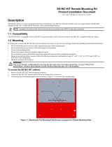
The 6860, an optional 4x40 red remote annunciator,
is shown in Figure 1. The 6860 can be surface or
flush-mounted.
Figure 1: Model 6860 Remote Annunciator
Compatibility
The 6860 is compatible with Honeywell’s Silent
Knight FACP's.
Note: For more information, see the FACP Installation manual.
Specifications
Mounting
Flush Mounting
Follow these steps to flush mount the 6860
1. The backbox measures 9-1/4” W x 8-3/8” H. The
backbox can be mounted prior to the complete
installation of the 6860 using any of the mounting
holes shown in Figure 2.
.
Figure 2: Backbox Mounting Holes
2. Remove knockout holes as needed for wiring.
See Figure 3 for backbox knockout locations
Figure 3: Backbox Knockout Locations
3. Wire the annunciator board to the main control
panel. See Figure 7.
4. Attach the annunciator/door assembly to
backbox as shown in Figure 4, using the supplied
Parameter Value
Operating Voltage: 24 VDC
Current
Standby: 25 mA
Alarm: 50 mA
Operating
Temperature:
0° to 49° C (32° to 120° F)
Dimensions:
Flush
Mount:
Overall: 12¼” W x 11½” H x 7/8” D
(31.1 cm W x 29.2 cm H x 2.2 cm
D) See “Flush Mounting” for back-
box dimensions.
Surface
Mount:
Including trim ring: 12¼” W x 11½”
H x 3” D (31.1 cm W x 29.2 cm H x
7.6 cm D)
mounting holes
mounting holes
wire knockouts
wire knockouts
wire knockouts

Silent Knight
®
, JumpStart
®
, and Honeywell
®
are registered trademarks of Honeywell International, Inc.
2 6860 Installation Document — P/N LS10174-001SK-E:A 07/01/2017
screws.
Figure 4: Attaching Annunciator/Door Assembly to
Backbox
Surface Mounting
1. Remove the desired knock out. See Figure 3.
2. To properly mount the backbox, insert a single
screw into the key shaped mounting hole. Do not
tighten all the way. See Figure 5. Place a level on
top of the backbox, with the backbox
level insert
the rest of the mounting
screws.
Figure 5: Backbox Surface Mount Holes
3. Connect wires from the 6860 to the SBUS
connectors on the FACP as shown in Figure 7.
4. The Model RA-100TR red trim ring kits is
available for use when surface mounting. Place
the trim ring over the backbox. See Figure 6.
Figure 6: Installing Trim Ring
5. Attach the door assembly to the backbox using
screws provided.
6. Replace the electronic assembly in the backbox.
Wiring Connections
Wire the 6860 to the FACP as Shown in Figure 7.
Figure 7: SBUS Connections
Installation
1. Ensure power is turned off at the panel.
2. Mount the 6860 in the desired location.
3. Connect the 6860 to the panel (see Figure 7).
4. Use the DIP switches on the back of the 6860 to
assign an ID number to the 6860 (see FACP
Installation Manual).
5. The 6860 module must be added to the system
through programming. JumpStart
®
Auto
Programming will add the module automatically
(refer to the FACP Installation Manual).
key shaped
mounting hole
backbox
mounting holes
/