
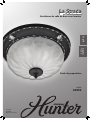
Bath Ventilator with Light
Owner’s Manual
La Strada
42929-01
20101026
©2010 Hunter Fan Co.
Model
82022
English
Español
Página 22
Français
Page 43

2
42929-01 10/26/2010
42929-01 10/26/2010
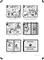
DISCONNECT
ELECTRIC
POWER SUPPLY
AND LOCK OUT
SERVICE PANEL
BEFORE
SERVICING UNIT
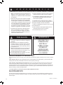
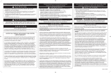
W A R N I N G
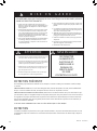
TO REDUCE THE RISK OF ELECTRIC SHOCK OR INJURY, OBSERVE THE FOLLOWING:
1. For general ventilating use only. Do not use for
ventilating hazardous or explosive materials.
2. To avoid motor bearing damage and noisy/unbal-
anced impellers, keep drywall spray, construction
dust, etc. off power unit.
3. DO NOT install this product in a wall. This prod-
uct is designed for installation in ceilings up to a
12/12 pitch (45 degrees). Ductwork must point
upward.
4. Please read specification label on product for fur-
ther information and requirements.
PREVENTATIVE MAINTENANCE
A clean fan provides better service. Disconnect the power supply and clean the fan as listed below.
TO CLEAN GRILLE:
Use a mild detergent, such as dishwashing liquid, and a soft cloth. DO NOT use abrasive cloths, steel wool pads
or scouring powders.
TO CLEAN FAN ASSEMBLY: Unplug motor cord from receptacle. To remove motor plate, find the single tab on the
motor plate (located next to the receptacle). Push up rear motor plate tab while pushing out on the side of the
housing or insert a screwdriver into the slot in the housing (next to tab) and twist screwdriver. Gently vacuum
fan, motor and interior of housing.
METAL AND ELECTRICAL PARTS SHOULD NEVER BE IMMERSED IN WATER.
MAINTENANCE
The motor is permanently lubricated and never needs oiling. If the motor bearings are making excessive or
unusual noises, replace the motor with the exact service motor. You should replace the impeller at the same
time.
C A U T I O N
W A R N I N G
1. Use this unit only in a manner intended by the manu-
facturer. If you have questions, contact the manufac-
turer at the phone number or address listed in the
warranty.
2. Before installing, servicing, or cleaning the unit,
disconnect the power by turning o the circuit break-
ers to the outlet box and associated wall switch loca-
tion. If you cannot lock the circuit breakers in the o
position, securely attach a prominent warning device,
such as a tag, to the service panel.
3. Installation work and electrical wiring must be done
by qualified person(s) in accordance with all applicable
codes and standards, including fire-rated construction
codes and standards.
4. When cutting or drilling into wall(s) or ceiling, do not
damage electrical wiring or other hidden utilities.
5. Ducted fans must always be vented to the outdoors.
Keep ducting as short and as straight as possible.
6. Acceptable for use over a bathtub or shower when
connected to a GFCI protected branch circuit.
7. Install fan at least 5 feet (1.52 m) above the floor.
8. Never place a switch where it can be reached from a
tub or shower.
9. This unit must be grounded.

E
F
G
H
I
J
M
N
O
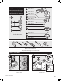
x4
*
*
*
NOTE:
Strain relief cable connector
must be installed. Not
Included.
A
B
C
95044-01-096
95029-01-000
77481-01-000
03242-01-232
95491-06-000
74508-03-133
97258-01-000
65219-01-000
77521-01-000
75184-01-092
97260-01-000
P
76079-02-481
Extra Screws
x2
D
K
L
3/8” Cable Connector
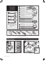
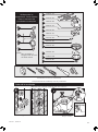
3
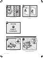
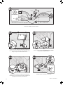
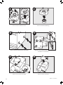
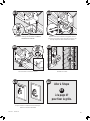
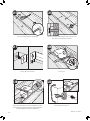
1
Turn off the power source.
Tools Needed. (Not supplied.)
Estimated assembly time: 30 to 60 minutes
Before Installation
Check all the parts.
If damaged, call
1-888-830-1326
for replacements.
2
F
J
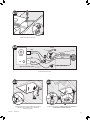
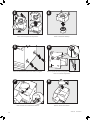
Loosen screws.
NOTE: Remove all packing materials before installation.
42929-01 10/26/2010
42929-01 10/26/2010

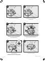
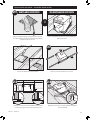
5
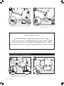
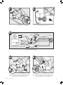
4
7
H
8
G
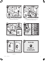
Remove the motor/blower from the housing.
4
3
I
F
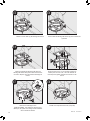
Remove the pre-loaded screw tip covers.
Remove the wiring cover screw.
6
Back out the pre-loaded screw tips until flush
with the side of the housing.
Remove the wiring cover.
Remove packing material.
42929-01 10/26/2010
42929-01 10/26/2010

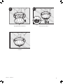
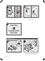
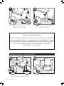
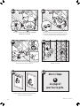
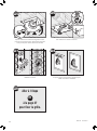
9
F
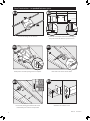
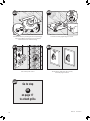
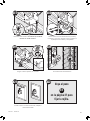
Pop out the first wiring access slug. Use second if needed. Insert the strain relief (not included) into the housing and
secure with washer.
Position the correct depth mark at the bottom edge of the
joist based on the thickness of your sheetrock.
New Construction - attaching to joist
5
10
B
C
Choose Installation Option
For New Construction - attaching to joist go to step A11, page 5
For New Construction - suspended between joists go to step B11, page 8
For Existing Construction - accessible from above go to step C11, page 11
For Existing Construction - accessible only from below go to step D11, page15
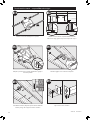
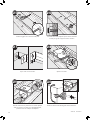
A11
F
5/8
1/2
5/8
1/2
A12
Screw pre-loaded screws into joist or framing.
42929-01 10/26/2010
42929-01 10/26/2010

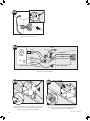
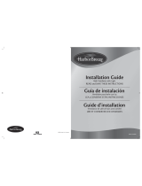
A
3 Pin
2 Pin
Fan Motor
Light
Light
Green
Black
Black
White
Black
Black
White
White
Bare Copper
Ground
A14
Main Switch 1 (AC In)
Switch 2 (AC In)
*Option Fan & Main Light Together
*Option
A13
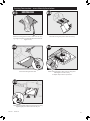
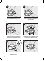
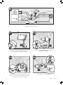
Route wires through the strain relief.
Connect wires as shown.
0
A16
Connect 4” duct and vent to the outside. Tape joints.
If ducting does not fit securely, an adapter may need
to be purchased.
6
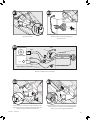
A15
F
H
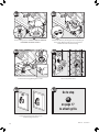
Install the wiring cover plate. Make sure all
wiring connections are inside the box or under
the wiring cover plate.
42929-01 10/26/2010
42929-01 10/26/2010

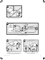
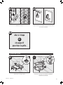
A19
J
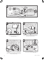
Secure the motor by tightening the 2 screws.
A20
Turn on the power source.
7
Connect wiring harness. DO NOT ALLOW THE MOTOR TO
HANG FROM THE WIRING HARNESS.
0000
A17
Reinstall the motor by inserting the tabs and pushing up
into position. Make sure the wires are not pinched
between the motor and the housing.
0000
I
A18
ON
OFF
A21
Test the motor. If the motor does not run, check the plug
connection.
A22
E1
Go to step
on page 17
to attach grille.
42929-01 10/26/2010
42929-01 10/26/2010

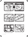
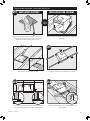
Slide the mounting rails into brackets.
Mark position of screws by using holes as a template.
Insert screws, leaving space between the screw
head and the joist. Screws are not provided.
New Construction – suspended between joists
8
B11
E
F
5/8
1/2
5/8
1/2
B12
1/8” bit
B14
B15
F
B13
Position the correct depth mark at the bottom edge of
the joist based on the thickness of your sheetrock.
Drill a hole in the center of each outline.
Attach the rails onto the screws.
B16
42929-01 10/26/2010
42929-01 10/26/2010

Tighten screws. Route wires through the strain relief.
Connect wires as shown.
9
B17
B18
A
3 Pin
2 Pin
Fan Motor
Light
Light
Green
Black
Black
White
Black
Black
White
White
Bare Copper
Ground
B19
Main Switch 1 (AC In)
Switch 2 (AC In)
*Option Fan & Main Light Together
*Option
B21
Connect 4” duct and vent to the outside. Tape joints.
If ducting does not fit securely, an adapter may need
to be purchased.
Install the wiring cover plate. Make sure all wiring
connections are inside the box or under the
wiring cover plate.
G
H
B20
42929-01 10/26/2010
42929-01 10/26/2010

10
B27
E1
Go to step
on page 17
to attach grille.
B22
I
Connect wiring harness. DO NOT ALLOW THE MOTOR TO
HANG FROM THE WIRING HARNESS.
I
B23
Reinstall the motor by inserting the tabs and pushing up
into position. Make sure the wires are not pinched
between the motor and the housing.
B25
Turn on the power source.
ON
OFF
B26
Test the motor. If the motor does not run,
check the plug connection.
B24
J
Secure the motor by tightening the 2 screws.
42929-01 10/26/2010
42929-01 10/26/2010

EXISTING FAN
C11
C12
E
F
Existing Construction – accessible from above
11
NO EXISTING FAN
8”
8 1/2”
OR
Remove an existing fan and check to make sure the
opening is large enough to accommodate the new
motor housing (8”x 8 1/2”).
Cut out an opening for the housing.
Use the motor housing as a template to mark position.
Slide the mounting rails into brackets.
Position the correct depth mark at the bottom edge of the
joist based on the thickness of your sheetrock.
5/8
1/2
5/8
1/2
C13
C14
Mark position of screws by using holes as a template.
42929-01 10/26/2010
42929-01 10/26/2010

C17
C18
C19
C20
12
C15 C16
Drill a hole in the center of each outline. Insert screws, leaving space between the screw head
and the joist. Screws are not provided.
Attach the rails onto the screws. Tighten screws.
Connect 4” duct and vent to the outside. Tape joints.
If ducting does not fit securely, an adapter may
need to be purchased.
Route wires through the strain relief.
42929-01 10/26/2010
42929-01 10/26/2010

C21
A
3 Pin
2 Pin
Fan Motor
Light
Light
Green
Black
Black
White
Black
Black
White
White
Bare Copper
Ground
C22
Main Switch 1 (AC In)
Switch 2 (AC In)
*Option Fan & Main Light Together
*Option
13
Tighten the strain relief screws.
Connect wires as shown.
C24
I
H
G
C23
Install the wiring cover plate. Make sure all wiring
connections are inside the box or under the
wiring cover plate.
Connect wiring harness. DO NOT ALLOW THE MOTOR TO
HANG FROM THE WIRING HARNESS.
42929-01 10/26/2010
42929-01 10/26/2010

C25
I
C26
J
C27
ON
OFF
C28
14
Secure the motor by tightening the 2 screws.
Turn on the power source.
Reinstall the motor by inserting the tabs and pushing up
into position. Make sure the wires are not pinched
between the motor and the housing.
Test the motor. If the motor does not run,
check the plug connection.
C29
E1
Go to step
on page 17
to attach grille.
42929-01 10/26/2010
42929-01 10/26/2010

EXISTING FAN
D11
F
D12
15
Existing Construction – accessible only from below
D13
2
1
D14
Route wires through strain relief.
Remove an existing fan and check to make sure the open-
ing is large enough to accommodate the new motor hous-
ing (8”x 8 1/2”).
Move the housing into position above the ceiling
Attach existing ducting to duct connector. Tape joints.
If ducting does not fit securely,
an adapter may need to be purchased.
F
D15
Install the housing flush with the sheetrock and secure by
tightening the pre-loaded screws into the joist.
42929-01 10/26/2010
42929-01 10/26/2010

16
A
3 Pin
2 Pin
Fan Motor
Light
Light
Green
Black
Black
White
Black
Black
White
White
Bare Copper
Ground
D16
Main Switch 1 (AC In)
Switch 2 (AC In)
*Option Fan & Main Light Together
*Option
I
D18
I
D19
D20
J
Connect wires as shown.
Reinstall the motor by inserting the tabs and pushing up
into position. Make sure the wires are not pinched between
the motor and the housing.
Connect wiring harness. DO NOT ALLOW THE MOTOR TO
HANG FROM THE WIRING HARNESS.
Secure the motor by tightening the 2 screws.
G
D17
H
Install the wiring cover plate. Make sure all wiring
connections are inside the box or under
the wiring cover plate.
42929-01 10/26/2010
42929-01 10/26/2010

17
ON
OFF
D22
D23
E1
Go to step
on page 17
to attach grille.
D21
Test the motor. If the motor does not run, check the plug
connection.
Turn on the power source.
Attaching the Grille
Remove the thumbscrews. Connect wiring harness. DO NOT ALLOW THE FIXTURE TO
HANG FROM THE WIRING HARNESS.
N
F
E1
M
E2
42929-01 10/26/2010
42929-01 10/26/2010

18
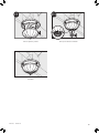
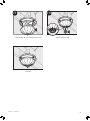
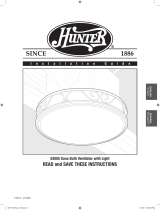
Install bulbs (not included).
E8
Attach thumbscrews.
WARNING: To reduce the risk of electrical shock,
all 4 thumbscrews MUST be properly installed.
N
E7
Align posts A, B, C and D (stamped into motor hous-
ing) with posts A, B, C and D (stamped into light
fixture). Slide light fixture over posts.
M
E6
42929-01 10/26/2010
42929-01 10/26/2010
M
E5
K
M
E4
M
E3
Remove the strain relief bracket screw. Position the strain relief bracket under the
motor as shown.
Insert the strain relief bracket’s dog-leg tab so that
it hooks over the lip of the motor. Reinstall the
strain relief bracket screw.

Align glass dome and push up.
19
E10
P
Screw finial into position.
E9
O
42929-01 10/26/2010
42929-01 10/26/2010
Complete.

20
42929-01 10/26/2010
42929-01 10/26/2010
Trouble Shooting
Problem: Fan does not come on.
Solution:
• Harbor Breeze Fan Bath Ventilators are extremely quiet. To conrm that the fan is running, place your hand
near the vents to feel the air movement.
• Turn power on, replace fuse, or reset breaker.
• Check all plug connections to be sure they are secure.
• Check the wiring to make sure it matches the wiring diagram.
Problem: Light does not come on.
Solution:
• Replace the light bulb with a new bulb.
• Turn power on, replace fuse, or reset breaker.
• Check all plug connections to be sure they are secure.
• Check the wiring to make sure it matches the wiring diagram.
Problem: Fan is noisy.
Solution:
• Check and tighten all fasteners.
• Check the glass to make sure it is secure.
• Check the apper to make sure it moves freely.
If you need parts or service assistance, please call 888-830-1326 or visit us at our web site at http://www.
hunterfan.com.
Page is loading ...
Page is loading ...
Page is loading ...
Page is loading ...
Page is loading ...
Page is loading ...
Page is loading ...
Page is loading ...
Page is loading ...
Page is loading ...
Page is loading ...
Page is loading ...
Page is loading ...
Page is loading ...
Page is loading ...
Page is loading ...
Page is loading ...
Page is loading ...
Page is loading ...
Page is loading ...
Page is loading ...
Page is loading ...
Page is loading ...
Page is loading ...
Page is loading ...
Page is loading ...
Page is loading ...
Page is loading ...
Page is loading ...
Page is loading ...
Page is loading ...
Page is loading ...
Page is loading ...
Page is loading ...
Page is loading ...
Page is loading ...
Page is loading ...
Page is loading ...
Page is loading ...
Page is loading ...
Page is loading ...
Page is loading ...
Page is loading ...
-
 1
1
-
 2
2
-
 3
3
-
 4
4
-
 5
5
-
 6
6
-
 7
7
-
 8
8
-
 9
9
-
 10
10
-
 11
11
-
 12
12
-
 13
13
-
 14
14
-
 15
15
-
 16
16
-
 17
17
-
 18
18
-
 19
19
-
 20
20
-
 21
21
-
 22
22
-
 23
23
-
 24
24
-
 25
25
-
 26
26
-
 27
27
-
 28
28
-
 29
29
-
 30
30
-
 31
31
-
 32
32
-
 33
33
-
 34
34
-
 35
35
-
 36
36
-
 37
37
-
 38
38
-
 39
39
-
 40
40
-
 41
41
-
 42
42
-
 43
43
-
 44
44
-
 45
45
-
 46
46
-
 47
47
-
 48
48
-
 49
49
-
 50
50
-
 51
51
-
 52
52
-
 53
53
-
 54
54
-
 55
55
-
 56
56
-
 57
57
-
 58
58
-
 59
59
-
 60
60
-
 61
61
-
 62
62
-
 63
63


Ask a question and I''ll find the answer in the document
Finding information in a document is now easier with AI
in other languages
Related papers
-
 Hunter Fan 90402 User manual
-
 Hunter Fan 27841 Owner's manual
-
 Hunter Fan 97318 Owner's manual
-
 Hunter Fan 22691 User manual
-
 Hunter Fan 27178 Owner's manual
-
 Hunter Fan 43044-01 User manual
-
 Hunter Fan 82021 Owner's manual
-
 Hunter Fan 82004 Owner's manual
-
 Hunter Fan 20091104 User manual
-
 Hunter Fan 90050 Owner's manual


Other documents
-
Hunter 97315 Table Top Fan Owner's manual
-
 Deco Breeze DBF0209 User manual
-
 Harbor Breeze Bath Ventilator with Light Installation guide
-
Carlon B708-SHK Operating instructions
-
-
 Hunter,R.F 83005 User manual
-
-
-
-


