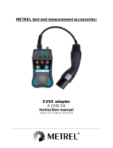
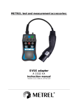
A 1632

METREL A 1632 Basic User's Manual

  • Hello! I am an AI chatbot trained to assist you with the METREL A 1632 Basic User's Manual. I’ve already reviewed the document and can help you find the information you need or explain it in simple terms. Just ask your questions, and providing more details will help me assist you more effectively!
A 1632 eMobility Analyser
Basic user guide
Version 1.1.4
2
Distributor:
Manufacturer:
METREL d.d.
Ljubljanska cesta 77
1354 Horjul
Slovenia
web site: http://www.metrel.si
© 2019 METREL
Mark on your equipment certifies that this equipment meets the
requirements of the EU (European Union) concerning safety and
electromagnetic compatibility regulations.
No part of this publication may be reproduced or utilized in any form or by any means without
permission in writing from METREL.
3
Table of contents
1 INTRODUCTION ........................................................................................................................6
2 THE A 1632 EMOBILITY ANALYSER ............................................................................................7
2.1 CONTENTS OF SET ...................................................................................................................... 7
2.2 USE CASES ................................................................................................................................ 8
2.3 EVSE TESTING ........................................................................................................................ 10
2.4 MODE 2 EV CABLE SAFETY TESTING ............................................................................................ 10
3 STANDARD EN 61851-1 ..........................................................................................................11
3.1 EV CONNECTOR TYPES .............................................................................................................. 11
3.1.1 Type 1 ........................................................................................................................11
3.1.2 Type 2 ........................................................................................................................12
3.1.3 Type 3 ........................................................................................................................12
3.1.4 Type 1 CCS ................................................................................................................13
3.1.5 Type 2 CCS ................................................................................................................14
3.1.6 CHAdeMO .................................................................................................................15
3.2 CHARGING CASES EXPLAINED ..................................................................................................... 16
3.2.1 Charging Case A .......................................................................................................16
3.2.2 Charging Case B .......................................................................................................16
3.2.3 Charging Case C .......................................................................................................17
3.3 CHARGING MODES EXPLAINED ................................................................................................... 17
3.3.1 Charging Mode 1 .......................................................................................................17
3.3.2 Charging Mode 2 .......................................................................................................18
3.3.3 Charging Mode 3 .......................................................................................................18
3.3.4 Charging Mode 4 .......................................................................................................19
3.4 CHARGING STATES ................................................................................................................... 19
3.5 MAX. CHARGING CURRENT (I.E. CHARGING SPEED) ........................................................................ 20
4 RECOMMENDED INSPECTIONS AND INSPECTION INTERVALS .................................................22
4.1 INSPECTION OF EVSE ............................................................................................................... 22
4.2 INSPECTION OF MODE 2 EV CABLE ............................................................................................. 22
4.3 INSPECTION OF MODE 3 EV CABLE ............................................................................................. 23
4.4 INSPECTION INTERVALS ............................................................................................................. 23
5 SETTINGS ON THE A 1632 AND MASTER INSTRUMENT ...........................................................24
5.1 PAIRING THE A 1632 EMOBILITY ANALYSER WITH THE MASTER INSTRUMENT................................... 24
5.2 SETTING THE A 1632 EMOBILITY ANALYSER OPERATING MODES ..................................................... 25
6 PERFORMING MEASUREMENTS..............................................................................................26
6.1 EVSE CHARGING STATION TESTING ............................................................................................. 27
6.1.1 Manual functional and diagnostic EVSE testing .......................................................28
6.1.2 Semi-automated functional and diagnostic EVSE testing .........................................30
6.1.3 Automated electrical safety EVSE testing .................................................................31
6.2 MODE 2 EV CABLE TESTING ...................................................................................................... 33
6.2.1 Manual functional Mode 2 EV cable testing .............................................................34
6.2.2 Manual diagnostic Mode 2 EV cable testing on the input side .................................35
6.2.3 Manual diagnostic Mode 2 EV cable testing on the output side ...............................35
4
6.2.4 Semi-automated functional and diagnostic Mode 2 EV cable testing on the output
side 35
6.2.5 Manual electrical safety testing of Mode 2 EV cable ................................................36
6.2.5.1 Continuity measurement (R low 200 mA) ........................................................36
6.2.5.2 Insulation measurement (R iso) .........................................................................37
6.2.5.3 RCD (IC-CPD / PRCD S+) measurement .........................................................38
6.2.5.4 Leakage current measurement ...........................................................................39
6.3 MODE 3 EV CABLE TESTING ...................................................................................................... 40
6.3.1 Manual electrical safety testing of Mode 3 EV cable ................................................40
6.3.1.1 Continuity measurement (R low 200 mA) ........................................................40
6.3.1.2 Insulation measurement (R iso) .........................................................................41
6.3.1.3 Leakage current measurement ...........................................................................41
6.3.1.4 Testing resistance coding for vehicle coupling and plug ..................................42
6.4 MONITORING WITH THE USE OF A 1631 EV MONITROING CABLE ................................................... 43
6.4.1 Monitoring of the charging process ..........................................................................43
7 SAVING DATA AND REPORTING ..............................................................................................45
8 ABBREVIATIONS ......................................................................................................................48
9 DOCUMENT VERSIONS ...........................................................................................................49
10 SOURCES.................................................................................................................................49
Table of figures
Figure 2.1: The A 1632 eMobility Analyser. ......................................................................................... 7
Figure 2.2: Use case 1 EVSE testing .................................................................................................. 8
Figure 2.3: Use case 2 Mode 2 EV cable testing ............................................................................... 8
Figure 2.4: Use case 4 Mode 3 EV cable testing ............................................................................... 9
Figure 2.5: Use case 5 Monitoring of charging process ................................................................... 9
Figure 3.1: Type 1 connector and pin layout ..................................................................................... 11
Figure 3.2: Type 2 connector and pin layout ..................................................................................... 12
Figure 3.3: Type 3 socket and connector........................................................................................... 13
Figure 3.4: Type 1 CCS connector/inlet and pin layout..................................................................... 14
Figure 3.5: Type 2 CCS connector/inlet and pin layout..................................................................... 15
Figure 3.6: CHAdeMO inlet/connector and pin layout ..................................................................... 16
Figure 3.7: Charging case A ................................................................................................................ 16
Figure 3.8: Charging case B ................................................................................................................ 16
Figure 3.9: Charging case C ................................................................................................................ 17
Figure 3.10: Charging mode 1 ............................................................................................................ 17
Figure 3.11: Charging mode 2 ............................................................................................................ 18
Figure 3.12: Charging mode 3 ............................................................................................................ 18
Figure 3.13: Charging mode 4 ............................................................................................................ 19
Figure 3.14: Levels of charging states ................................................................................................ 20
Figure 3.15: Charging speed ............................................................................................................... 21
Figure 5.1: Pairing the A 1632 eMobility Analyser with a master instrument ................................ 24
Figure 5.2: Toggeling between operating modes (Mode 1 and Mode 2) ........................................ 25
5
Figure 6.1: Starting the EVSED test with Master Instrument ........................................................... 26
Figure 6.2: 3-Basic EVSE configurations ............................................................................................. 27
Figure 6.3: Manual functional EVSE testing ....................................................................................... 28
Figure 6.4: Manual diagnostic testing ................................................................................................ 29
Figure 6.5: Semi-automated functional testing................................................................................. 30
Figure 6.6: Semi-automated diagnostic testing ................................................................................ 31
Figure 6.7: Electrical safety testing .................................................................................................... 32
Figure 6.8: 1-Phase Mode 2 EV cable (left) and 3-Phase Mode 2 EV cable (right) configuration .. 33
Figure 6.9: Manual functional Mode 2 EV cable testing ................................................................... 34
Figure 6.10: Manual diagnostic Mode 2 EV cable testing on the input side ................................... 35
Figure 6.11: Manual continuity measurement procedureon a 1-phase Mode 2 EV cable ............. 36
Figure 6.12: Manual insulation measurement procedure on a 1-phase Mode 2 EV cable ............ 37
Figure 6.13: Manual IC-CPD measurement procedure on a 1-phase Mode 2 EV cable ................. 38
Figure 6.14: Manual leakage measurement procedure on a 1-phase Mode 2 EV cable ................ 39
Figure 6.15: 3-Basic Mode 3 EV cable configuration ........................................................................ 40
Figure 6.16: Manual continuity measurement procedureon a 3-phase Mode 3 EV cable ............. 41
Figure 6.17: Manual resistance coding measurement procedure on a 3-phase Mode 3 EV cable 42
Figure 6.18: 3-Basic monitoring configuration .................................................................................. 43
Figure 6.19: CP communication monitoring during EV charging ..................................................... 44
Figure 7.1: Saving the results on the Master Instrument under the EVSE structure object ........... 45
Figure 7.2: EVSE report example in MESM (part 1) .......................................................................... 45
Figure 7.3: EVSE report example in MESM (part 2) .......................................................................... 46
Figure 7.4: Starting MESM Help ......................................................................................................... 46
Figure 7.5: MESM Help ....................................................................................................................... 47
Table of tables
Table 1: Type 1 CCS inlet/connector pins .......................................................................................... 13
Table 2: Type 2 CCS inlet/connector pins .......................................................................................... 14
Table 3: Maximum Mode 1 charging capabilities ............................................................................. 17
Table 4: Maximum Mode 2 charging capabilities ............................................................................. 18
Table 5: Maximum Mode 3 charging capabilities ............................................................................. 19
Table 6: Maximum Mode 4 charging capabilities ............................................................................. 19
A 1632 eMobility Analyser
6
1 Introduction
EVSE equipment testing is another sub-field of installation safety testing. As charging currents
are high the charging equipment requires special attention in case of faults.
The EV charging equipment is constantly being put into use, which means it has to be regularly
inspected and tested to maintain its functionality and reliability. Metrel has developed a special
adapter to be able to do this, the A 1632 eMobility Analser, which covers the international
standard EN 61851-1 for testing EVSE equipment and EN 60364-7-722 for testing special
installations or locations supplies for electric vehicles.
This guide user guide covers an overview of the EN 81851-1standard.
The test diagrams presented in this booklet are designed as a guideline for people involved in
testing of EVSE equipment with A 1632 eMobility Analser.
The guide itself cannot replace the standards EN 61851-1 and EN 60364-7-722 which have been
used as a reference for preparation of this booklet.
For clarification on any part of this guide, contact Metrel d.d.
7
2 The A 1632 eMobility Analyser
The A 1632 eMobility Analyser is an adapter that can be used together with an installation
tester, acting as a Master Instrument, to test Electrical Vehicle Supply Equipment (EVSE), Mode 2
and Mode 3 Electrical Vehicle (EV) charging cables and perform monitoring during charging.
The installation tester behaves as the Master Instrument and is capable of even controlling the
A 1632 to some extent. The following Metrel instruments support the use of the A 1632
eMobility Analyser:
MI 3155 EurotestXD
MI 3152 EurotestXC
MI 3152H EurotestXC 2,5 kV
MI 3325 MultiServicerXD
Android App (in development phase)
Figure 2.1: The A 1632 eMobility Analyser.
2.1 Contents of set
The A 1632 eMobility Analyser comes together with the following accessories:
A 1633: Mains supply cord 1 phase 10 A plug to 3 phase 16 A plug adapter
A 1634: Test cable with Type 2 male plug connector, length 2 m
A 1635: Test lead 2 mm / 4 mm safety banana plug adapter, red, length 1 m
A 1271: Bag for accessories
Instruction manual
Calibration certificate
8
2.2 Use cases
The A 1632 eMobility Analyser is intended to be used in the following use cases:
EVSE testing
o EVSE functional testing
o EVSE diagnostic testing
o EVSE electrical safety testing
Figure 2.2: Use case 1 EVSE testing
Mode 2 EV cable testing
o Mode 2 EV cable functional testing
o Mode 2 EV cable diagnostic testing
o Mode 2 EV cable electrical safety testing
Figure 2.3: Use case 2 Mode 2 EV cable testing
9
Mode 3 EV cable testing
o Mode 3 EV cable electrical safety testing on input and output side of A 1632
Figure 2.4: Use case 4 Mode 3 EV cable testing
Monitoring of the charging process
Figure 2.5: Use case 5 Monitoring of charging process
10
2.3 EVSE testing
The eMobility Analyser is capable of presenting itself to the EVSE as an EV (part of the
instrument that is marked with blue linning). To do this the A 1632 can simulate the following EV
states:
A EV not connected to EVSE.
B EV connected, EVSE not charging.
C EV connected, EVSE charging.
D EV connected, EVSE charging, ventilaiton requred by EVSE (e.g. during High Power
Chanrging HCP or when the EV has lead batteries installed).
With the A 1632 it is possible to simulate the following errors on the EVSE equipment:
Err1 /
sh
Diode short
Err2 / CP
sh
CP-PE short (loss of communication between EVSE and EV).
Err3 / PE
op
PE open
2.4 Mode 2 EV cable safety testing
The A 1632 is capable of testing Mode 2 and Mode 3 EV charging cables. When testing Mode 2
EV cables, it is possible to test them as an EVSE charging station or as an appliance. When tested
as an EVSE charging station, the EV cable has to be connected to a 1-phase shucko inlet or a 3-
phase CEE wall inlet. When tested as an appliance both parts of the cable have to be connected
to the A 1632.
With the A 1632 we can simulate fauts on the mains, i.e. the input side of the analyser. These
faults allows us to verify the relevant safety features of the Mode 2 EV cable. The errors that can
be simulated using only the A 1632 are:
L/L1
op
L/L1 conductor opened
L/L2
op
L/L2 conductor opened
L/L3
op
L/L3 conductor opened
N
op
N conductor opened
PE
op
PE conductor opened
L
PE
L/L1and PE conductors crossed
U
EXT
(PE) External voltage on PE (on input side)
Note: safety testing of Mode 2 EV charging cables is only possible when using the A 1632
eMobility Analyser. Support through Master Instruments is not possible.
Please refer to the A 1632 eMobility Analyser instruction manual for more details!
11
3 Standard EN 61851-1
3.1 EV connector types
3.1.1 Type 1
Facts:
The Type 1 connector also referred to as the “Yazaki connector” by the Japanesse
manufacturer or the “J1772 connector” as it was published in SAE J1772.
The connector supports only 1-phase AC charging up to 32 A.
Mostly used in US and Japan and in some case also in Europe. The latest Europen
Directive has now enforced the Type 2 and Type 2 CCS connectors.
Type 2 and Type 1 connectors use the same CP and PP signalling, that is why one may use
adapters in between.
The Type 1 connector has 5 pins:
L/L1 conductor
L2/N conductor
PE conductor
CP pin for communication during charging
CS or PP pin for determining the maximum charging current allowed.
Figure 3.1: Type 1 connector and pin layout
Testing of AC charging stations with installed Type 1 connector is possible with the A 1632. An
additional adapter between the Type 2 male connector and Type 1 socket is needed.
12
3.1.2 Type 2
Facts:
Described in detail in IEC/EN 61851-1
Know also as the Mennekes connector by the German manufacturer.
Supports 1-phase AC charging up to 70 A or 3-phase AC charging up to 63 A.
Used mostly within the European Union, since its regulation requires all public AC
charging stations to be equipped with a Type 2 socket or a Type 2 connector.
Type 2 and Type 1 connectors use the same CP and PP signalling, that is why one may use
adapters in between.
The Type 2 connector has 7 pins:
L1 conductor
L2 conductor
L3 conductor
N conductor
PE conductor
CP pin for communication during charging
PP pin for determining the maximum charging current allowed.
Figure 3.2: Type 2 connector and pin layout
Testing of AC charging stations and EV charging cable with either a Type 2 connector or socket is
fully supported.
3.1.3 Type 3
Facts:
Know also as Scame connector by the Italian manufacturer.
Supports tree different geometries; 1-phase AC charging at up to 16 A, without control
pilot contact; 1-phase AC charging at up to 32 A and 3-phase AC charging at up to 63 A.
Formerlly used mostly in Italy and France. The latest EU regulation requires all public AC
charging stations to be equipped with a Type 2 socket or a Type 2 connector. For this
reason Type 3 connections are no longer used.
13
Figure 3.3: Type 3 socket and connector
Testing of AC charging stations with installed Type 3 is not supported with the A 1632.
3.1.4 Type 1 CCS
Facts:
Type 1 CCS is a DC charging system.
Type 1 CCS inlet on the EV allows both AC and DC charging via a Type 1 and Type 1 CCS
connectors used respectively.
Only male inlets exist for Type 1 (CCS) AC and DC charging. These may be installed only
on the EV and never on the EVSE.
CCS stands for Combined Charging Standard.
The Type 1 CCS inlet/connector has the following pins:
Conductor/pin
Inlet
Connector
L/L1
L2/N
PE
CP
PP
DC-
DC+
Table 1: Type 1 CCS inlet/connector pins
14
Figure 3.4: Type 1 CCS connector/inlet and pin layout
Even thought that the Type 1 and Type 1 CCS connectors use the same low-level communication
(i.e. the CP pin), testing of DC charging stations with installed Type 1 CCS is not supported with
the A 1632. The reason is that the CCS connection requires also high level communication which
the A 1632 does not have.
3.1.5 Type 2 CCS
Facts:
Type 2 CCS is a DC charging system.
Type 2 CCS inlet on the EV allows both AC and DC charging via a Type 2 and Type 2 CCS
connectors used respectively.
Only male inlets exist for Type 2 CCS DC charging. These may be installed only on the EV
and never on the EVSE.
CCS stands for Combined Charging Standard.
The Type 2 CCS inlet/connector has the following pins:
Conductor/pin
Inlet
Connector
L1
L2
L3
N
PE
CP
PP
DC-
DC+
Table 2: Type 2 CCS inlet/connector pins
15
Figure 3.5: Type 2 CCS connector/inlet and pin layout
Even thought that the Type 2 and Type 2 CCS connectors use the same low-level communication
(i.e. the CP pin), testing of DC charging stations with installed Type 2 CCS is not supported with
the A 1632. The reason is that the CCS connection requires also high level communication which
the A 1632 does not have.
3.1.6 CHAdeMO
Facts:
CHAdeMO is an abbreviation of CHArge de MOve, equivalent to charge n go.
Japanesse standard.
Not compatible with Type 1 or Type 2 low level communication.
Used only for DC charging.
Available also in most public charging stations in Europe.
The CHAdeMO inlet/connector has the following pins:
1. GND
2. Start/Stop charger
3. NC (not connected)
4. Start/Stop charging process
5. DC-
6. DC+
7. Control pilot ( for connection control)
8. CAN bus High signal
9. CAN bus Low signal
10. Start/Stop charger.
16
Figure 3.6: CHAdeMO inlet/connector and pin layout
The CHAdeMO is a DC charging connector. Tha Japaneese have also implemented their own high
level communication protocol. Due to both reasons descirbe, the DC charging stations with
CHAdeMO connectors cannot be tested with the A 1632.
3.2 Charging cases explained
3.2.1 Charging Case A
Cable and vehicle connector are permanently attached to the EV. This case is actually not used.
Figure 3.7: Charging case A
3.2.2 Charging Case B
Cable and vehicle connector detachable at both ends (EV and EVSE). Normally used in Mode 2
and Mode 3 charging, where the EVSE charging station is private or semi-private.
Figure 3.8: Charging case B
17
The A 1632 eMobility Analyser allows testing AC charging stations with Case B charging. To be
able to test the EVSE’s safety features, be sure to set the Proximity Pilot (PP) knob to the
appropriate level in order to simulate the maximum allowed charging current.
3.2.3 Charging Case C
Cable and vehicle connector permanently attached to the EVSE. Used with public charging
stations, especially in the case of fast charging or high power charging (HPC).
Figure 3.9: Charging case C
The A 1632 eMobility Analyser allows testing AC charging stations with Case C charging. To be
able to test the EVSE’s safety features, be sure to set the Proximity Pilot (PP) knob state N.C. (not
connected).
3.3 Charging modes explained
3.3.1 Charging Mode 1
Charging mode 1 was intended for charging EVs at home using only a simple able with 1- or 3-
phase shuko/CEE plug on one side and a Type 2 or Type 1 female connetor on the EV side.
Figure 3.10: Charging mode 1
The maximum charging capabilities for Mode 1 charging can be seen from the table below:
Nominal current
Nominal voltage
Output power
1-phase
16 A
230 V a.c.
3,7 kW
3-phase
16 A
400 V a.c.
11,1 kW
Table 3: Maximum Mode 1 charging capabilities
Allowed connection cases for Mode 1 charging: B
Important: Since this cable does not offer any additional protection it has been
banned from actual use.
18
3.3.2 Charging Mode 2
This charging mode is used for charging an EV anywhere (e.g. at home) using a 1-phase shuko or
3-phase CEE socket. It has an integrated IC-CPD device used for functional safety and an (P)RCD
which provides electrical safety. The Mode 2 EV cable also has a heating sensor acting as an
additional safety function which disconnects the charging if the temperature of the wall inlet
exceeds maximum allowed temperature of the Mode 2 cable.
Figure 3.11: Charging mode 2
The maximum output power is 7.4 kW for 1-phase charging and 22.2 kW for 3-phase charging as
seen from the table below:
Nominal current
Nominal voltage
Output power
1-phase
32 A
230 V a.c.
7,4 kW
3-phase
32 A
400 V a.c.
22,2 kW
Table 4: Maximum Mode 2 charging capabilities
Of course normal households would typicly have less than 32 A of nominal current avaialbe,
therefore the out put power for a 1-phase connection would actually be approx. 3,7 kW.
Allowed connection cases for Mode 2 charging: B
Testing of Mode 2 EV charging cables is possible with the use of the A 1632 eMobility Analyser.
3.3.3 Charging Mode 3
This is the safest way of private, semi-private and public charging. These types of charging
stations are AC type. The maximum power produced by such EVSE equipment is 7,3 kW when
used with a 1-phase connection or up to 43,6 kW when used with a 3-phase connection. The
most common charging power in public settings is 225,1 kW as the currents usually do not
exceed 32 A.
Figure 3.12: Charging mode 3
19
The maximum charging capabilities for Mode 3 charging can be seen from the table below:
Nominal current
Nominal voltage
Output power
1-phase
63 A
230 V a.c.
14,5 kW
3-phase
63 A
400 V a.c.
43,7 kW
Table 5: Maximum Mode 3 charging capabilities
Allowed connection cases for Mode 3 charging: B, C
Testing of Mode 3 charging stations is possible with the use of the A 1632 eMobility Analyser.
3.3.4 Charging Mode 4
This mode is used for fast charging a.k.a high power charging. The typical output power is
currently from 50 to 120 kW although EVSE equipment with up to 400 kW can already be seen
on the market.
Figure 3.13: Charging mode 4
The maximum charging capabilities for Mode 4 charging can be seen from the table below:
Nominal current
Nominal voltage
Output power
DC
100 A
500V d.c.
50 kW
DC
125 A
400 V d.c.
50 kW
DC
350 A
500 V d.c.
175 kW
DC
500 A
900 V d.c.
450 kW
Table 6: Maximum Mode 4 charging capabilities
The charging speed is on the rise as manufacturers of DC charging equipment keep rising the
charging current and voltage. Some manufacturers advertise their DC charging stations are
capable of producing approx. 450 kW.
Allowed connection cases for Mode 4 charging: C
The A 1632 eMobility Analyser does not support testing of DC charging stations (e.i. Mode 4
charging).
3.4 Charging states
The Control Pilot (CP) is used when charging an EV with a Mode 2 EV cable or a Mode 3 EVSE.
The pin is intended for communication between the EV and the charging unit. With it the EV
introduces itself to the charging station and requests charging. The EVSE charging station is the
master in this case since it decides whether or not the EV connected can be charged.
20
According to the EN 61851-1 standard, the following CP states are defined:
A EV not connected to EVSE.
B EV connected, EVSE not charging.
C EV connected, EVSE charging.
D EV connected, EVSE charging,ventilaiton requred by EVSE.
E Error.
Figure 3.14: Levels of charging states
The EVSE sets the duty cycle of the PWM control pilot (CP) signal to indicate the maximum
current that the EV may draw from the EVSE. The EV must than apply a resistive load accordingly
as not to request more current than the charging station is willing to provide. Typically this will
be seen as a transition from state x1 to x2, where x can be any of the known states (A, B, C or D).
State x1 indicates the unavailabilty whereas state x2 indicates the availability of power supply to
the EV.
3.5 Max. charging current (i.e. charging speed)
Charging speed is determined through the Proximity Pilot (PP). The PP is a resistor connected
between the PP pin and the PE pin on the Type 2 connector or socket of a Mode 2 EV cable, a
Mode 3 EVSE charging station or the EV. The coding of the resistor actually determines what
cable is being used (the cross section) which further determines the maximum charging current
and consequently charging speed. The PP resistor can have the following values according to EN
61851-1:
1500 Ω 13 A Charging cable
680 Ω 20 A Charging cable
220 Ω 32 A Charging cable
100 Ω 63 A Charging cable
Cables used for DC charging usually offer higher charging currents from 100 A to 400 A or even
500 A. All cables that use a charging current of more than 200 A must have some sort of cooling
installed inside the cable (water or transformator oil).
Additionally the charging speed is determined by the EVSE through the duty cycle of the Pulse
Width Modulation (PWM) signal. The higher the duty cycle the faster the charging as can be
/