Page is loading ...

iridium PotsDOCK 9555
Installation
& User Manual
Suitable for the Iridium 9555
Portable Satellite Telephone
Beam Communications Pty Ltd

2
iridium PotsDOCK 9555
Installation and User Manual
Beam Communications Pty Ltd
5/8 Anzed Court, Mulgrave,
Victoria, 3170, AUSTRALIA
Information furnished by Beam Communications Pty Ltd (Beam) is believed to be
accurate and reliable. However, no responsibility is assumed by Beam for its use,
or for any infringement of patents or other rights of third parties, which may result
from its use. No license is granted by implication or otherwise under any patent
or patent rights of Beam. Beam reserves the right to change specications at any
time without notice.
Copyright © 2018 Beam Communications Pty Ltd. All rights reserved
User Information
Please record your serial number here for
future reference:
Model: PotsDOCK 9555
Serial no.:
This number can be copied from the white label on the
PotsDOCK 9555
Eg. PD500001
Product name: PotsDOCK 9555
Manual revision: 10
Part Number: USRMAN004710
Release date: August 2018

PotsDOCK 9555 Installation & User Manual
3
Beam Communications
Beam Communications, a wholly owned subsidiary of World
Reach Limited (WRR), listed on the Australian Stock Exchange, is a
world leader in design, manufacture and distribution of specialized
communications equipment for the Iridium Satellite Network.
Beam’s commitment to be at the forefront has continued to increase
its share of the global satellite communications market. Its premium
distribution network spans the world.
Recognized as a leading provider of satellite communication solutions,
Beam specializes in Voice, Data, Tracking and customized solutions.
Beam develops innovative products and services to meet market
demands and niche applications.
Beam’s leading edge products are deployed in a wide range
of vertical markets including Maritime, Transport, Government,
Defence, Mining, Construction, Forestry, Emergency Services, Relief
Aid, Telemetry and Rural Telephony.
Supported by a dedicated team of professionals, Beam has developed
solid relationships with its peers and network of distributors worldwide.
Beam Communications Pty Ltd
5/8 Anzed Court, Mulgrave,
Victoria, 3170, AUSTRALIA
Web: www.beamcommunications.com
Info: [email protected]
Support: [email protected]
Tel: +61 3 8588 4500
Fax: +61 3 9560 9055

4
Conventions in this Manual
Warnings, cautions and notes appear throughout this manual and are
represented by following conventions.
WARNING / CAUTION:
This symbol and associated text indicate a warning note providing
information to prevent damage to equipment or personal injury.
NOTE / IMPORTANT / TIP:
This symbol and associated text indicate a note providing general
operating information.
INTERFERENCE:
All wireless phones may get interference, this could aect performance.
RECORD:
Write details of your unit for easy reference when required. Ideal
when troubleshooting.
Terminology
TERM DESCRIPTION
Bluetooth ® The Bluetooth® word, mark and logos are owned by Bluetooth® SIG, Inc.
Other trademharks and trade names are those of their respective owners.
PDMS PotsDOCK Management System - MS Windows Install
POTS Plain Old Telephone Service
RJ11 Connector type and reference for the POTS telephone port
SMS Short Message Service
SBD Short Burst Data
Mobile
Originating
Describes a call initiated by the PotsDOCK
Mobile
Terminating
Describes an incoming call being answered by the PotsDOCK
9555 The Iridium 9555 Satellite Telephone
On-hook RJ11 POTS Phone handset is hung up.
Off-hook RJ11 POTS Phone handset is picked up.
® The ® symbol, mark and logos are owned by the respective
companies of which the symbol follows. Any use of such marks by
Beam Communications is under license. Other trademarks and trade
names are those of their respective owners.
REN Ringer Equivalent Number (REN) is a number denoting the electrical
load a telephone ringer has on the line.
RF Radio Frequencies
AT AT tension
SMA SubMiniature version A co-axial RF connection

PotsDOCK 9555 Installation & User Manual
5
Package Contents
Check that your PotsDOCK 9555 package contains:
1 x PotsDOCK 9555 Docking Cradle
1 x AC/DC Power Adaptor
1 x DC Power Cable / Lead
1 x RAM Bracket
3 x M4 Screw Set
User Manual
Quick Start Guide
Optional Accessories
The following optional accessories are available for your PotsDOCK 9555
• Beam Privacy Handset Kit (RST755i)
• Iridium Antenna and Cable Kits
• Man Down Kit (RST410)
• Beam GoalZERO UPS Battery Pack (RST060)
See your service provider for pricing and availability of these quality
Beam accessories.
Additional Information
For the latest in supporting software and documentation for PotsDOCK
9555 please visit
www.beamcommunications.com/support/potsdock9555
DATA
To use data on the PotsDOCK, the specic Beam USB driver must
be installed on the PC connecting to the PotsDOCK, downloaded
from the above link.
ALERT/TRACKING
To congure the alert / tracking functionality on your PotsDOCK,
you must rst install the PotsDOCK Management System (PDMS)
software, which also includes the specic Beam USB drivers.
OTHER RESOURCES AVAILABLE ONLINE
- Advanced Conguration – inbuilt to PDMS
- Quick Start Guide & Manual
- Iridium Direct Internet
- Antenna Installation Guide
- AT Command Set
- 9555 Upgrade if required

6
Contents
BEAM Communications 3
Conventions in this Manual 4
Terminology 4
Package Contents 5
Optional Accessories 5
Additional Information 5
Safety Information 8
WARNING: POTENTIALLY EXPLOSIVE ATMOSPHERES 8
Safety – Iridium Transceiver 9555 9
Electronic Devices 10
Pacemakers 10
Other Medical Devices 10
Vehicles 10
Posted Facilities 10
Aircraft 10
For Vehicles Equipped with an Air Bag 10
About this equipment 11
POTSDOCK 9555 KEY FEATURES 11
Tracking / Alert Monitoring 12
Equipment Overview: 13
Installation Guidelines 14
Routing Cables (for vehicle installations) 14
Guidelines for Electrical Connections 15
Installation Procedure 16
Installing the PotsDOCK Cradle 17
Cradle Mounting 17
Iridium Antenna connection 18
GPS Antenna connection (optional) 18
RJ11 / POTS Telephone (optional) 19
External Alert Button (optional) 19
Privacy Handset (optional – extra order) 20
Preliminary Testing 21
Prepare the Iridium 9555 Handset 21
Connect Power 21
Wiring for a Marine Application 22
PotsDOCK 9555 Usage 23
Docking & undocking your 9555 handset 23
Removing the 9555 from vehicle 23
Call Testing 24
Bluetooth® Conguration (Optional) 25
Bluetooth® Headset Conguration 25
Tracking & Alert Conguration (Optional) 25
Operation of the PotsDOCK 9555 26
Starting Up 26
Charging the Iridium 9555 Handset 26

PotsDOCK 9555 Installation & User Manual
7
Placing Voice Calls 27
RJ11 POTS Phone Call – Mobile Originating 27
RJ11 POTS Phone Call – Mobile Terminating 28
Bluetooth® Phone Call - Mobile Originating 28
Bluetooth® Phone Call – Mobile Terminating 29
Privacy Handset Use 29
Mute & Earpiece-Jack Mode 30
Mute functionality 30
Ringer Selection 30
Earpiece-Jack Mode 31
Tracking & Alert Operation 31
Enable Tracking & Alert 31
Send Tracking position 31
Activate Alert Mode 32
Clearing an Alert 32
PotsDOCK Front Panel 33
Data Communications 34
Using the USB Data Port 34
USB Driver Installation 35
AT Commands 36
Setting the Baud Rate 36
Iridium 9555 Display Denitions 37
Power-On Messages 38
Assuring Quality of Iridium Service 39
Obstructions 39
Cabling 39
RF Interference 40
Symptoms of RF Interference 40
Mitigation of RF Interference 40
Specication Summary 41
Electrical & Environmental Specications 41
Cradle Mounting Dimensions 43
PotsDOCK Dimensions in millimeters 43
Trouble Shooting 44
For additional product support: 46
Beam Warranty Terms & Conditions 46

8
Safety Information
IMPORTANT!
Please read the following information carefully before installing and
using the Beam PotsDOCK 9555. Failing to follow instructions may
compromise the safety of the product and may result in personal
injury and/or equipment damage. Please consult your supplier if you
have any further questions.
The PotsDOCK 9555 is a low power docking station for the 9555
handset. When ON, it will charge the 9555 handset whilst docked in
the PotsDOCK 9555.
Refer to the appropriate section of this PotsDOCK 9555 Installation &
User Manual for additional safety information.
◊ Store the system in a cool and dry area.
◊ Do not submerge the system in water.
◊ Do not place foreign metal objects or debris in the system. If debris
enters into the system, please return to factory for service.
WARNING:
DO NOT open equipment. There are no user-serviceable parts inside.
If a DC power supply is to be used, its output must comply with the
Safety Extra Low Voltage (SELV) requirements of IEC60950.
All connectors except the RJ11 line socket must only be connected
to equipment ports which comply with the Safety Extra Low Voltage
(SELV) requirements of IEC60950.
WARNING:
POTENTIALLY EXPLOSIVE ATMOSPHERES
• Turn your phone OFF and DO NOT remove your battery or
remove the 9555 handset from the cradle when you are in any
area with a potentially explosive atmosphere.
• Obey all signs and instructions.
• Sparks from your battery in such areas could cause an explosion
or re resulting in bodily injury or even death.
• Areas with a potentially explosive atmosphere are often but not
always clearly marked. They include, but are not limited to:
» fuelling areas such as gasoline stations
» below deck on boats;
» fuel or chemical transfer or storage facilities;
» areas where fuel odors are present (for example, if a gas/
propane leak occurs in a car or home);
» areas where the air contains chemicals or particles, such
as grain, dust, or metal powders;
» any other area where you normally would be advised to
turn o your vehicle engine.

PotsDOCK 9555 Installation & User Manual
9
Safety – Iridium Transceiver 9555
Your 9555 handset is a low power radio transmitter and receiver. When
it is ON, it receives and also sends out radio frequency (RF) signals.
(NOTE: Refer to Iridium 9555 Phone Manual for additional Information)
◊ The Iridium 9555 handset has an in-built Iridium transceiver which
is designed to be used with an external antenna. This antenna
transmits RF energy. The Iridium antenna (tted via an extension
coaxial cable to the cradle) must be located more than > 0.3
meters (1 foot) from human body (person) when in operation.
◊ International agencies have set standards and recommendations
for the protection of public exposure to RF electromagnetic energy.
♦
International Commission on Non-Ionizing Radiation
Protection (ICNIRP) 1996
♦ Verband Deutscher Elektrotechniker (VDE) DIN-0848
♦ United States Federal Commission, Radio Frequency
Exposure Guidelines (1996)
♦ National Radiological Protection Board of the United
Kingdom, GS 11, 1988
♦ American National Standards Institute (ANSI) IEEE. C95.
1-1992
These standards are based on extensive scientic review by
scientists, engineers, and physicians from universities, government
health agencies, and industry groups. They review the available
body of research to develop ANSI standard. These ANSI standards
are reviewed regularly for research development.
◊ Do not operate your satellite telephone when a person is within
1 foot (30 centimeters) of the antenna. A person or object within
1 foot (30 centimeters) of the antenna could impair call quality
and may cause the phone to operate at a higher power level than
necessary and expose that person to RF energy in excess of that
established by the FCC RF Exposure Guidelines.
◊ As a precaution, please maintain the maximum body distance
possible from the antenna during call transmission.
WARNING: ROAD SAFETY COMES FIRST!
Do not use a hand-held cellular terminal, satellite phone or mobile
when driving a vehicle, unless it is securely mounted in a holder
for speaker phone operation. Before making a call with a handheld
terminal, satellite phone or mobile, park the vehicle stationary.
Please obey local road laws for hands-free speakerphone operation.
Speakerphones (hands-free) must be installed by qualied personnel.
Faulty installation or operation can constitute a safety hazard.
IMPORTANT!
Cellular & Satellite terminals or mobiles operate using radio
signals and communication networks. Because of this, the connection
cannot be guaranteed at all times or under all conditions. Therefore,
you should never rely solely upon any wireless device for essential
communications, for example emergency calls.

10
Electronic Devices
Most modern electronic equipment is shielded from RF signals.
However, certain equipment may not be shielded against the RF signals
from your wireless phone.
Pacemakers
The Health Industry Manufacturers Association recommends that a
minimum separation of six inches (6”) be maintained between a wireless
phone’s antenna and a pacemaker to avoid potential interference with the
pacemaker. These recommendations are consistent with the independent
research by and recommendations of Wireless Technology Research.
Persons with pacemakers:
◊ Should ALWAYS keep the phone more than six inches from their
pacemaker when phone is turned ON
◊ Should turn the phone OFF immediately if you have any reason to
suspect interference is taking place
Other Medical Devices
If you use any other personal medical device, consult the manufacturer of
your device to determine if it is adequately shielded from external RF energy.
Your physician may be able to assist you in obtaining this information.
Turn your phone OFF in health care facilities when any regulations
posted in these areas instruct you to do so. Hospitals or health care facilities
may be using equipment that could be sensitive to external RF energy.
Vehicles
RF signals may aect improperly installed or inadequately shielded
electronic systems in motor vehicles. Check with the manufacturer or
its representative regarding your vehicle. You should also consult the
manufacturer of any equipment that has been added to your vehicle.
Performance of electronically controlled brake and/or guidance systems
can, under certain unique conditions, be subject to interference by mobile
radio operation. Although the transceiver exceeds all requirements
regarding RF emissions, you should mount the transceiver as far as
possible from the guidance system and/or braking modulator box
(usually located in the trunk) to minimize any interference.
Posted Facilities
Turn your phone OFF in any facility where posted notices require such
as hospitals and on-board aircraft.
Aircraft
Airline regulations prohibit using your phone while in the air. Consult
the local Aviation Authority for guidelines on use of the equipment on
board an aircraft.
For Vehicles Equipped with an Air Bag
An air bag inates with great force.
Do NOT place objects, including both installed and portable wireless
equipment, in the area over the air bag or in the air bag deployment area.
If in-vehicle wireless equipment is improperly installed and the air bag
inates, serious injury could result.

PotsDOCK 9555 Installation & User Manual
11
POTSDOCK 9555 KEY FEATURES
POTSDOCK CRADLE
• Securely holds 9555 handset
• Robust design and construction
• Charges 9555 handset ready for use
• Integrated antenna connection
• Integrated USB connectivity
POTS/RJ11
• Supports standard cordless & corded
telephones (5 REN)
• The POTS phone can be run 600m (2000 ft)
from unit
• Easily integrated to PBX system
• Ring, busy & dial tones
• Superior voice quality
TRACKING/GPS
• In-built GPS engine
• Tracking & alert monitoring capable
• Periodic position reports or remotely polled
• Triggered position status message
• Also compatible with other tracking applications
PANIC/ALERTS
• Panic Alert button in-built to cradle
• Option of additional wired alert buttons
INTEGRATED BLUETOOTH®
• Bluetooth® in-built in cradle
• Supports Bluetooth® voice connectivity
IN-BUILT RINGER
• In-built ringer for enhanced ring indication
VOICE, DATA, SMS, SBD
• Supports all Iridium voice, data, SMS &
SBD services
• Access to prepaid, post paid & crew calling
PRIVACY HANDSET
• Supports optional Beam privacy handset
• Auto sensing answer/hang-up intelligence
INSTALLATION
• Supports 9 - 32V DC power input
• Flexible installation via universal mount,
also suitable for wall mounting
• Supplied with 110 - 240V AC/DC Plug pack
QUALITY
• Professional industrial design
• 2 year replacement guarantee for
peace of mind
• 100% factory tested
• Full certied, Iridium, RoHS, CE,
IEC60945, AS/EN60950
About this equipment
PotsDOCK 9555 is an
intelligent compact docking
station specically
designed for the Iridium
9555 satellite handset.
PotsDOCK allows the 9555
handset to be used in a
wide variety of applications.
It enables you to use an
intelligent RJ11/POTS
connection with a standard
corded, cordless or DECT
handset. Alternatively, it can
also be interfaced with a
PBX system.
PotsDOCK also has an
in-built Bluetooth® module
for voice connectivity.
Equipped with internal
GPS, the PotsDock
provides an intelligent
tracking and alert
reporting system that can
be easily congured to
support periodic polling or
emergency alert reporting.

12
Tracking / Alert Monitoring
PotsDOCK has an in-built GPS module that can provide simple tracking,
monitoring and alert management in various land and sea based
applications within various types of vehicles, vessels or xed site locations.
The GPS module provides pinpoint accuracy and enables tracking
worldwide. The tracking function has to be congured and enabled
on the PotsDOCK via the PDMS. Once turned on, tracking and
alert messages can be sent to a phone number, e-mail address,
or tracking application via SMS or Short Burst Data (SBD) if congured
on the 9555 handset.
Tracking messages can be sent from the PotsDOCK in the following ways;
1. Periodic position reporting, which is preset during conguration
of the PotsDOCK
2. A current location position can be sent at any time by pressing the
Track button on the front of the PotsDOCK
The Alert mode can be activated on the PotsDOCK in the following ways;
1. Use the two button press (know as the Alert button) on the front
of the cradle
2. Use an external alert button/emergency push button connected to
the alert loop
Once activated, alert messages will be sent to the preset destination
continuously until the alert is disabled either remotely or locally on
the PotsDOCK unit.

PotsDOCK 9555 Installation & User Manual
13
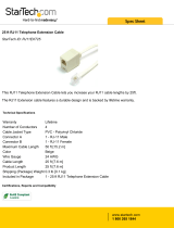
Equipment Overview:
EJECT Button
RJ11 Port
Mini USB Data
Port
Iridium Antenna
(TNC Female)
GPS Antenna
(SMA Female)
Alert Loop (In/Out)
Input Power
(4-way Microt)
Privacy Handset
(4-pole, 3.5mm)
9555 Handset
Antenna Plug
3-Button Panel
Interface

14
Installation Guidelines
This guide outlines the process for installing the Beam PotsDOCK 9555
in conjunction with an Iridium 9555 portable handset.
This kit must not be used with any other device other than the Iridium
9555 handset.
◊ Only qualied personnel should install communication equipment. If
necessary, contact the vehicle manufacturer for air bag information
specic to the vehicle.
◊ Ensure that the units are protected from dirt and moisture.
◊ Select an area to mount components that do not interfere with
driver or passengers seating or leg space.
◊ Ensure that each mounting surface is strong enough to support
the component being mounted to prevent the component from
loosening over time.
◊ Mount all components securely to prevent shifting that could cause
injury or could interfere with safe vehicle operation. Always use the
supplied mounting hardware.
◊ Leave space around the units to allow cooling and ensure there are
adequate clearance for cables.
◊ Ensure the units can be easily removed.
Routing Cables (for vehicle installations)
If your vehicle is equipped with wiring troughs in the doorsills, use them to
simplify cable installation and to provide maximum protection for the cables.
If wiring troughs are not available, route cables according to these
guidelines:
◊ Route cables so they are protected from pinching, sharp edges,
and crushing
WARNING:
Air bags inate with great force. DO NOT place objects, including
communication equipment, in the area over the air bag or in the air
bag deployment area. If the communication equipment is improperly
installed and the air bag inates, serious injury could result.
◊ Where possible, avoid routing cables above the catalytic converter
◊ Use grommets wherever a cable must pass through a hole in a
metal panel
◊ In a vehicle equipped with electronically controlled anti-skid brakes,
route all cables on the opposite side of the vehicle from the braking
modulator box to minimize possible interference from the phone.
◊ Keep all in-line connectors accessible.
◊ The suggested path for routing cables in vehicles without wiring
troughs is alongside the drive shaft hump, under the carpet.

PotsDOCK 9555 Installation & User Manual
15
Guidelines for Electrical Connections
The system is designed to operate in negative ground 9 to 32 Volt DC
electrical systems only. IF using the DC cable lead:
◊ The best power connection point for the positive primary power
leads is the positive terminal of the vehicle battery. Often, direct
connection to the battery is inconvenient, and you may nd it easier
to connect the positive leads to the starter solenoid. Always select
a point as close as possible to the battery.
◊ Connect the negative primary power leads to a good ground point
on the vehicle chassis or at the battery. If you must attach the
negative primary power lead(s) directly to the negative pole of the
battery, you may optionally insert a 10-amp fuse (not included) into
the ground (0V) line. Failure to insert a fuse can cause equipment
to overheat IF a wiring fault exists.
◊ Many parts of a vehicle can produce electrical noise that interferes
with the electrical radio system operation. The ignition system is the
most common source of electrical noise interference. Before you
begin installation, ensure that the ignition wiring and connections
to the vehicle battery are in good working condition.
◊ Verify that low resistance connections are present between the
battery negative terminal, the vehicle chassis, and the engine
block. All wire connections should be clean and tight.
At 13.6 volts, the PotsDOCK cradle draws a maximum of 1 amp current.
Please ensure that the vehicle’s battery and alternator have sucient
current capacity to deliver at least 1 amp more than the maximum
current that may be required by the vehicle and its other accessories.
WARNING:
Do not connect the PotsDOCK interface power cable to power the
unit until the full installation is completed.

16
Installation Procedure
Installing the PotsDOCK Cradle
Install the components in the following order.
More detailed instructions can be found in the
sections following.
1. Mount the PotsDOCK cradle
2. Install the external Iridium and/or GPS
antenna (ordered as extra option)
3. Install the RJ-11 POTS telephone
(optional)
4. Install the privacy handset (ordered as
extra option)
5. Install the external alert button (option)
6. Connect power to the PotsDOCK cradle
7. Congure Bluetooth® (optional)
8. Congure Tracking / Alert (optional)
When selecting a location for the PotsDOCK
cradle, consider these guidelines:
◊ Ensure that each mounting surface is strong enough to support
the cradle.
◊ Allow enough room so that you can easily insert the 9555 handset
into and remove it from the cradle.
◊ Ensure that the PotsDOCK is within cable distance of power and
antenna connections
◊ Position the handset and cables so that it does not interfere with
vehicle operation or with driver or passenger seating or leg space.
◊ Ensure sucient room is allowed for the antenna and interface
cables to be routed from the rear of the PotsDOCK.

PotsDOCK 9555 Installation & User Manual
17
Cradle Mounting
The PotsDOCK is supplied with a universal RAM®-mount bracket that
enables mounting to any at surface (vertical or horizontal) within a
vehicle, attached on a wall or on a table as required.
1. Attached one pivot base to the rear of the PotsDOCK using the M4
screws supplied.
Pivot base bolted on
2. Secure the second pivot base to the location you have selected for
mounting the PotsDOCK.
Pivot Base RAM Mount
3. Use the interconnecting stem of the RAM mount to secure the
PotsDOCK to the pivot base and tighten into the desired location
rmly using the wing nut on the stem.
Finished result

18
Iridium Antenna Connection
The antenna connections exits from the
rear of the PotsDOCK cradle, via the
antenna loom as shown in the picture.
Install the Iridium antenna in the
appropriate location (with clear sky view)
and then connect it to the TNC female
connector on the antenna cable coming
from the rear of the PotsDOCK.
GPS Antenna Connection (Optional)
The GPS connection is optional if the
tracking function is not required. If
connected, and tracking is enabled,
position or location information will be
shown on your tracking messages and
alert messages.
The GPS connection supports an active
GPS antenna compatible with powering
from a 3.3V source.
Install the GPS antenna in the appropriate
location and then connect it to the SMA
female connector on the antenna cable
coming from the rear of the PotsDOCK.
WARNING:
DO NOT pull with force on the cables from the rear of the
PotsDOCK. Please install strain relief clamping for the antenna
cables where required.
Correct installation of the antenna system is a vital part of the
PotsDOCK system, to ensure reliable functionality, and drop-free calls.
Use only quality low-loss antenna cabling, and ensure that the
cable(s) and connectors to the antenna provide no more than 3dB
attenuation (at frequency of 1.6GHz)
NOTE:
Refer to the section “Assuring Quality of Iridium Service” for more
information on antenna placement and installation

PotsDOCK 9555 Installation & User Manual
19
NOTE:
Antenna should only be connected and disconnected to the GPS
receiver when the PotsDOCK is not powered. Connecting the
antenna after power-up can result in prolonged acquisition time.
RJ11 / POTS Telephone (Optional)
Any standard analogue POTS Telephone (POTS = Plain Old Telephone
Service) is supported by the PotsDOCK. It supplies power to the
analogue phone as well as Ring, Dial and Busy tones.
1. Route the telephone cabling (up to 600m) from the PotsDOCK.
2. Mount the analogue phone if required, and plug the RJ11 cable into
the PotsDOCK RJ11 port.
The RJ11 port uses the middle 2 pins of the RJ socket, which is
standard for analogue telephone cables.
External Alert Button (optional)
PotsDOCK provides an additional cable
pair from its rear cable loom, known as the
standard Beam alarm-loop. This provides
a Normally-CLOSED wire loop, which can
be used to connect to any passive type of
button, or relay, or reed switch in which the
action breaks the loop (OPEN) to activate
the alarm state.
Connect the BROWN and GREEN wires
either directly to the button, or it can be
extended for longer runs (up to 45 meters).
This alarm loop can support multiple alarm
buttons / switches – wired in SERIES,
whereby any one of these buttons will
OPEN (activate) the loop when pressed.
To properly register the alarm state, the
loop needs to be OPEN for at least 2
seconds – (ie. holding down the button for
2 seconds activates the alarm).

20
Privacy Handset (Optional – Extra Order)
The PotsDOCK provides a 4-pole 3.5mm audio socket on the rear cable
loom, for connection to the Beam privacy handset. This provides local
handset function, conveniently mounted next to the PotsDOCK cradle.
1. The Privacy Handset Kit (purchased/ordered separately) contains
a mounting bracket, space plate, and fasteners.
2. Mount the handset cup to the mounting plate.
3. Mount the spacer plate and the mounting bracket to the rear of the
PotsDOCK, by using the longer screws provided with the kit. The
original RAM arm-bracket plate is also re-installed behind these plates.
4. Plug the Privacy Handset 4-pole connector into the rear
cable loom. (Please use suitable electrical tape and/or strain relief
clamps where required to ensure reliable connection)
Privacy Handset mode is enabled when the handset is removed from
the cup. Please ensure to re-dock the Privacy Handset when not in use.
/