
INSTALLATION INSTRUCTIONS
ELECTRIC FREE-STANDING RANGE
NOTICE D'INSTALLATION
CUISINIÈRE ENCASTRÉE ÉLECTRIQUE
INSTRUCCIONES DE INSTALACIÓN
ESTUFA ELÉCTRICA INDEPENDIENTE

Table of content
Important Safety Instructions ................................................... 3
Preparation ................................................................................ 5
Procedure .................................................................................. 7
Prepare Electrical Connection ................................................... 7
Install Electrical Connection ....................................................... 8
Complete the installation ....................................................... 11
Installation of anti-tip bracket ................................................. 11
Service ..................................................................................... 11
Table des matières
Consignes de sécurité importantes ........................................ 12
Préparation .............................................................................. 14
Procédure ................................................................................ 16
Préparation du raccordement électrique ................................. 16
Installation du raccordement électrique ................................... 17
Compléter l'installation .......................................................... 21
Installation de l'étrier anti-bascule .......................................... 21
Dépannage ............................................................................... 21
Índice
Instrucciones de seguridad importantes ................................ 22
Preparación .............................................................................. 24
Procedimiento ......................................................................... 26
Preparar la conexión eléctrica ................................................. 26
Instalar la conexión eléctrica .................................................... 27
Finalizar la instalación ............................................................ 30
Instalación del soporte anticaídas ........................................... 30
Servicio técnico ....................................................................... 30

3
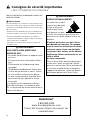
, Important Safety Instructions
READ AND SAVE THESE INSTRUCTIONS
PLEASE READ ALL INSTRUCTIONS BEFORE USING THIS
APPLIANCE.
, WARNING
If the information in this manual is not followed exactly,
a fire or explosion may result causing property damage,
personal injury or death.
and an authorized repair service.
literature package for this range.
, WARNING
WHAT TO DO IF YOU SMELL GAS:
-
call the fire department.
Installation and service must be per-
formed by a qualified installer, authorized
service agency or the gas supplier.
, WARNING
TIP OVER HAZARD!
tip the range over
and be killed.Verify
that the anti-tip
bracket is securely
installed. Ensure the anti-tip bracket is
engaged when the range is moved.
Do not operate the range without the
anti-tip bracket in place. Failure to fol-
low the instructions in this manual can
result in death or serious burns to chil-
dren and adults.
Check for proper installation and use
of anti-tip bracket
Carefully tip range forward pulling from
the back to ensure that the anti-tip
bracket engages the range leg and pre-
vents tip-over. Range should not move
more than 1" (2.5 cm).
Questions?
1-800-944-2904
www.boschappliances.com
We look forward to hearing from you!

4
Safety Codes and Specifications
grounded by a qualified technician in accordance
latest edition and local electrical code requirements.
and grounding must comply with all applicable codes.
It is the responsibility of the owner and the installer
to determine if additional requirements and stan-
dards apply in specific installations.
Equipment and Usage Safety Requirements
proper equipment to move.
heated surface units, cabinet storage space located
above the surface units should be avoided. If cabi
-
net storage is provided, the risk can be reduced by
installing a range hood that projects a minimum of 5"
(12.7 cm) beyond the bottom of the cabinets.
range. Never allow children to play with packaging
material.
other servicing should be done by a qualified techni
-
damage to the range.
removing leveling legs, panels, wire covers, anti-tip
-
for storage.
when reaching behind or under range.
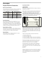
Power Requirements and
Electrical Grounding Instructions
-
the circuit breaker or fuse box in case of an emer
-
gency.
, Important Safety Instructions
READ AND SAVE THESE INSTRUCTIONS

5
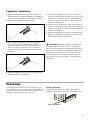
Parts provided:
Installations)
Note: not necessary for Canadian installations
Tools and parts needed:
Canadian installations)
concrete screws)
Additional Parts Needed For
Hard Wire Installations
Note: Power Supply Cord Kit Not Necessary For
Hard Wire Installations
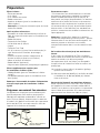
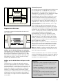
Cabinet Requirements
walls and projecting surfaces constructed of com-
between cabinets where range is to be installed
(0.47" (12 mm) clearance from range sidewall to
cabinet required in Canada).
30” (76.2 cm) Minimum
between cabinets
Required Clearances:
measure 36" (91.4 cm) high x 24" (61 cm) deep.
Cabinets over the cooking surface and cabinets adja-
cent to those over the cooking surface measure 13"
(33 cm) deep from backwall. If nonstandard cabinets
are used, care should be taken to alter dimensions
accordingly.
Note: -
self-cleaning ovens; the cabinets may discolor or
stain.
From cooktop to materials above:
between the top of the cooking surface and the bot-
tom of an unprotected wood or metal cabinet.
24" (61 cm) is acceptable when the bottom of the
wood or metal cabinet is protected by
material which must be covered with
aluminum or copper.
From range walls to adjacent materials:
No clearance is required from unit walls to adjacent
vertical combustible walls on rear, right or left.
Clearance from range top to adjacent vertical walls
must be at least 4" (10.2 cm).
30in (76.2 cm )
min. centered
30in (76.2 cm) min.
4in (10.2 cm)
min
4in
(10.2 cm
)
min
no clearance required (12 mm clearance from
range sidewall to cabinet required in Canada.)
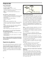
Preparation

6
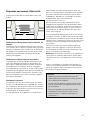
Electrical Requirements
space.
21” (533.4 mm)
30”
(762 mm)
7 1/2”
(190.5 mm)
3 1/2”
(88.9 mm)
4 1/2”
(114.3 mm)
4 1/2”
(114.3 mm)
Verify that wiring to house is adequate.
Contact your local utility company to verify that the
present electric service to your home is adequate. In
some instances, the size of the wiring to the house
and service switch must be increased to handle the
electrical load demanded by the range.
Verify that wiring inside house is adequate.
separate disconnect switch and fuses either in the
main entrance panel or in a separate switch and
require that electrical wiring be done by licensed
to the electric codes in place in your region.
General Information
circuit breaker sizes based upon the supply voltage
for each model.
We recommend that the range be installed with a
electrical rating of the power cord set must be
set shall be marked
range can also be hard wired using the aluminum
terminal lugs included in the literature pack. If using
(not supplied).
-
fer to your local electric code requirements in order
to determine the required amperage.
for the circuit. In compliance with the NEC, a sepa-
rate circuit is also recommended.
Note: In Canada, the range is shipped from the fac-
tory with the range cord already installed. Proceed
the strain relief and connect the range cord (or wire
conductors) as described in the following steps.
Tips:
· -
ning while installing the range.
·
or a piece of cloth under the range to protect
·

7
Procedure
Prepare Electrical Connection
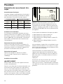
Electrical Specifications
Check data plate for kW rating. Reference kW rating
in table to determine amperage requirements.
kW Rating AMPS Required
Volts
Volts
Canadian
12.3 9.2 40 or 50* 40 or 50*
12.6 9.5 40 or 50* 50
13.5 10.2 50 50
* Varies by location. Refer to local electric code.
Install Ventilation
We strongly recommend the installation of a ven-
-
cording to instructions furnished with the hood.
Prepare Walls and Floor
-
structions (extra electrical or gas connections, etc.)
so that range will rest against wall properly.
Prepare Range
Place range in front of cabinets where it is to be
installed. Remove any packaging.
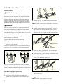
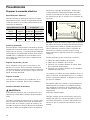
Install Strain Relief
, WARNING
beproperly installed.
Place strain relief in knockout below terminal block.
-
per instructions included with strain relief.
Feed range cord through strain
relief in knockout panel here.
Electrical connection
(found behind terminal block cover)
Tip:
can be removed from the range to install the strain
relief: Remove panel from range, install strain relief
back panel.
-
mended method, but where local codes permit,
three wire connections are also acceptable.
can also be hard wired with either a three or four
wire connection. In this case, the terminal lugs sup-
plied must
be used.
-
information.

8
Install Electrical Connection
Connect Electric
, WARNING
the range cord should not be cut or removed under
any circumstances. It must be plugged into a match-
ing grounding type receptacle and connected to a
correctly polarized 240- Volt circuit. If there is any
doubt as to whether the wall receptacle is properly
grounded, have it checked by a qualified electrician.
, WARNING
the neutral conductor is prohibited for new branch-
circuit installations (1996 NEC), mobile homes, and
recreational vehicles, or in an area where local codes
prohibit grounding through the neutral conductor.
-
tral conductor is prohibited,
(a) disconnect the link from the neutral,
(b) use grounding terminal or lead to ground unit,
(c) connect neutral terminal to lead branch circuit
neutral in usual manner
(when the appliance is to be connected by means of
a cord kit, use 4-conductor cord for this purpose)
instructions included with cord.
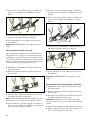
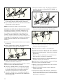
Four Wire Range Cord Connection
(Recommended Method)
1.
Remove the terminal block cover to expose the
terminal block.
2. Remove top nut, star washer, and round washer
from each post.
Note: remove last round washer, last nut or
internal wiring leads.
3. Remove screw from bottom end of ground strap.
4. Remove ground strap from center post, rotate so
that wide end is at top and attach wide end to
ground strap
green ground screw
ground wire
5.
6.
7.
red
white
black
8.-
minal block cover.
9. Properly secure strain relief (see previous sec-
tion).
Note:

9
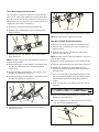
Three Wire Range Cord Connection
where local codes and ordinances permit grounding
through neutral and where conversion to four wire is
impractical, the unit may be connected to the power
supply via a three wire connection.
1.
2. Remove the terminal block cover to expose the
terminal block.
3. Remove top nut, star washer, and round washer
from each post.
Note:
internal wiring leads.
4.
center post.
5.
6.
red
white
black
ground strap
7. -
minal block cover.
green ground screw
8. Properly secure strain relief (see previous section).
Note:
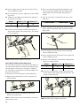
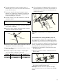
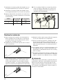
Four Wire Flexible Conduit Connection
1.
2. Remove the terminal block cover to expose the
terminal block.
3. Remove the top nut, star washer, and round
washer from each post.
Note:
internal wire leads.
4. Remove screw from bottom end of ground strap.
5.
6.
manual) through hole below terminal block with
ground screw.
7. Place one terminal lug (packaged with this man-
ual) on each post. Replace the star washer and
round washer and secure with 20" pounds of
torque.
8.
the wire.
3/8 “
9. Insert the insulated grounding wire into the lug
below the terminal block.
10. Insert stripped end of white wire into the center
lug
clamping screw
wire

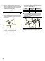
10
11. Insert stripped end of red wire into the left lug.
12.-
ing screw.
13. -
ate torque (see table).
Gauge
Torque Torque (Nm)
6 35 3.95
8 25 2.82
14.
is now complete.
red wire
white wire
green
ground
screw
black wire
green ground wire
Note:
Three Wire Flexible Conduit Connection
-
cal codes and ordinances permit grounding through
-
cal, unit may be connected to the power supply via a
three wire connection.
1.
2. Remove the terminal block cover to expose the
terminal block.
3. Remove the top nut, star washer, and round
washer from each post.
Note:
internal wire leads.
4. Place one terminal lug (packaged with this man-
ual) on each post. Replace the star washer and
round washer and secure with 20" pounds of
torque.
5.
each wire.
3/8 “
6. Insert stripped end of white wire into the center
-
ping screw.
lug
clamping screw
wire
7. Insert stripped end of red wire into the left lug.
8. Insert stripped end of black wire into the right lug.
9.
Gauge
Torque Torque (Nm)
6 35 3.95
8 25 2.82
10. -
wiring is now complete.
green ground screw
Note:

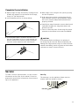
11
information at the front of the manual. Please be
prepared to provide the information from the data
tag on the appliance.
Data Tag
Service
1.-
justable leg supports on the bottom of the range,
2.
3.
wood or anchorless concrete screws (included).
4.
into the receptacle.
5.
back leg slides under the antitip bracket. Range
will sit ¾" (19 mm) away from back wall when
properly installed.
6. Carefully tip range forward to ensure that the anti
tip bracket engages the range back brace and
prevents tip-over.
7.
,
CAUTION
the wiring may be reversed. Reversed polarity can
damage the range and can result in electrical shock
hazard. Immediately switch off power at the breaker
Complete the installation
Data Plate
Page is loading ...
Page is loading ...
Page is loading ...
Page is loading ...
Page is loading ...
Page is loading ...
Page is loading ...
Page is loading ...
Page is loading ...
Page is loading ...
Page is loading ...
Page is loading ...
Page is loading ...
Page is loading ...
Page is loading ...
Page is loading ...
Page is loading ...
Page is loading ...
Page is loading ...
Page is loading ...

-
 1
1
-
 2
2
-
 3
3
-
 4
4
-
 5
5
-
 6
6
-
 7
7
-
 8
8
-
 9
9
-
 10
10
-
 11
11
-
 12
12
-
 13
13
-
 14
14
-
 15
15
-
 16
16
-
 17
17
-
 18
18
-
 19
19
-
 20
20
-
 21
21
-
 22
22
-
 23
23
-
 24
24
-
 25
25
-
 26
26
-
 27
27
-
 28
28
-
 29
29
-
 30
30
-
 31
31
-
 32
32


Bosch HES7052U/08 Installation guide
- Type
- Installation guide
- This manual is also suitable for
Ask a question and I''ll find the answer in the document
Finding information in a document is now easier with AI
in other languages
- français: Bosch HES7052U/08 Guide d'installation
- español: Bosch HES7052U/08 Guía de instalación
Related papers
-
Bosch Benchmark 1101841 Installation guide
-
Bosch HEI8054U/01 Installation guide
-
-
-
Bosch HES7132U/01 Installation guide
-
-
Bosch HEI7052U/08 Installation guide
-
Bosch HES5022C/01 Installation guide
-
Bosch HES7062U/01 Installation guide
-
Other documents
-
Siemens HE2416U/01 User manual
-
Siemens HD2515U/02 User manual
-
KitchenAid W10246119C User manual
-
Jenn-Air JES9750CAS02 Installation guide
-
Legrand radiant Receptacle, 15A Installation guide
-
JennAir JDS1450FP Installation guide
-
KitchenAid KERS807SSS05 Installation guide
-
-
Whirlpool GY397LXUB Owner's manual
-
KitchenAid JDS1450DS Installation guide