
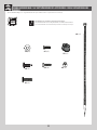
TABLE OF CONTENTS
5/16" (≈8 mm)
5 mm (Included)
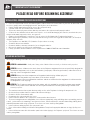
CONTACT LIFETIME CUSTOMER SERVICE:
Call: 1-800-225-3865
7:00 am–5:00 pm (Monday–Friday) MST
and 9:00 am–1:00 pm Saturday MST
Live Chat: www.lifetime.com/customerservice
(click on “LIVE CHAT” tab)
QUESTIONS?
MODEL# AND PRODUCT ID (you will need both when contacting us)
Model Number: 90980 / 290980
Product ID:
Pour le français, voir la page 2. Para el español, ver la página 3.
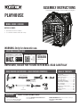
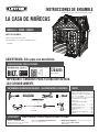
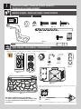
ASSEMBLY INSTRUCTIONS
MODEL #60091
PLAYHOUSE
MODEL 90980 / 290980
BEFORE ASSEMBLY:
• Assemble on a level surface
• 2+ adults recommended for setup
IMPORTANT, RETAIN FOR FUTURE REFERENCE: READ CAREFULLY
(1)
Included
(1)
(1)
(1)
(1)
(1)
(2)
(1)
Icon Legend................................4
Warnings and Notices..................5
Safety Information.....................6
Safe Play Area..........................9
Spare Parts Bag........................10
Lower Walls Assembly................11
Upper Walls Assembly...............34
Parts Identifi er.........................i-iv
Roof Assembly..........................60
Maintenance Instructions..........91
Registration..............................94
Warning Sticker........................95
Warranty...................................97
(1)
ADDITIONAL ASSEMBLY HELP
For assembly help, scan: or search
1208205
in the BILT app.
TOOLS REQUIRED (NOT INCLUDED—UNLESS INDICATED OTHERWISE)
WARNING: Only for domestic use.
Page is loading ...
Page is loading ...
Page is loading ...

5
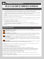
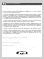
WARNINGS & NOTICES / AVERTISSEMENTS ET AVIS / ADVERTENCIAS Y AVISOS
Most injuries are caused by misuse and/or not following instructions. Use caution when using this product.
To ensure safety, do not attempt to assemble this product without following the instructions carefully. Check entire box and inside all packing
material for parts and/or additional instruction material. Before beginning assembly, read the instructions and identify parts using the hardware
identifi er and parts list in this document. Proper and complete assembly, use and supervision are essential for proper operation and to reduce the
risk of accident or injury. A high probability of serious injury exists if this product is not installed, maintained, and operated properly.
FAILURE TO FOLLOW THESE WARNINGS MAY RESULT IN SERIOUS INJURY OR PROPERTY DAMAGE AND WILL VOID WARRANTY.
Owner must ensure that all players know and follow these rules for safe operation of the system.
• If using a ladder during assembly, use extreme caution.
• Two capable adults are recommended for this operation.
• Be aware that parts can be damaged by overtightening the screws.
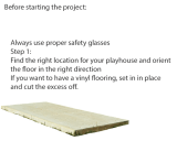
• All who participate in the assembly process should wear safety glasses throughout the assembly.
• This Playhouse is not suitable for children under three years.
SAFETY INSTRUCTIONS
La mayoría de las lesiones ocurren a causa del mal uso y/o por no seguir las instrucciones. Tenga precaución al usar este producto.
A fi n de garantizar la seguridad, no intente ensamblar este producto sin seguir cuidadosamente las instrucciones. Revise en toda la caja y dentro de
todos los materiales del empaque que estén las partes y/o material de instrucción adicional. Antes de comenzar el montaje, lea las instrucciones e
identifi que las piezas utilizando el identifi cador de herrajes y la lista de piezas en este documento. Un ensamblado adecuado y completo, el uso y la
supervisión son fundamentales para tener una operación adecuada y reducir el riesgo de accidentes o lesiones. Existe una alta probabilidad de sufrir
lesiones graves si este producto no se instala, no se le da mantenimiento y/o no se opera de manera adecuada.
NO SEGUIR ESTAS ADVERTENCIAS PUEDE RESULTAR EN LESIONES GRAVES O DAÑOS A LA PROPIEDAD Y ANULARÁ LA GARANTÍA.
El propietario debe asegurarse de que todos los jugadores conozcan y sigan estas reglas para el funcionamiento seguro del sistema.
• Si usa una escalera durante el ensamblado, extreme precauciones.
• Para esta actividad se recomienda contar con el apoyo de dos adultos en posibilidad de llevar a cabo dicha actividad.
• Tenga en cuenta que las piezas pueden dañarse si los tornillos se aprietan de más.
• Todas las personas que participen en el proceso de ensamblado deben usar anteojos de seguridad durante todo el ensamblado.
• Esta casita de juegos no es adecuada para niños menores a tres años.
INSTRUCCIONES DE SEGURIDAD
La majorité des accidents résultent d’une mauvaise utilisation et/ou du fait de n’avoir pas suivi les consignes. Observez toutes précautions utiles pendant
l’utilisation de ce produit.
Pour assurer votre sécurité, ne tentez pas d’assembler cet article sans avoir lu et suivi toutes les consignes attentivement. Vérifi ez la totalité de la
boîte et l’intérieur de tous les matériaux d’emballage pour trouver toutes les pièces et/ou matériau contenant des consignes supplémentaires. Avant
de commencer le montage, identifi ez toutes les pièces et tous les accessoires et faites-en l’inventaire en les comparant aux listes et identifi cateurs
de pièces et accessoires contenus dans ce document. Un assemblage correct et complet, ainsi que l’utilisation et la supervision correctes sont des
conditions essentielles à la bonne direction et diminuent les risques d’accident ou de blessure. Une haute probabilité d’accident grave résulte de
mauvaises conditions d’installation, maintenance et/ou utilisation.
LE NON-RESPECT DE CES AVERTISSEMENTS PEUT RÉSULTER EN ACCIDENTS GRAVES OU DOMMAGES MATÉRIELS ET ANNULER LA GARANTIE.
Le propriétaire doit veiller à ce que tous les joueurs connaissent et suivent ces règles pour une exploitation sûre du système.
• Agissez avec la plus grande prudence si vous employez une échelle pour l’assemblage.
• Il est recommandé que cet assemblage soit exécuté par deux personnes adultes.
• Il est possible d’endommager les pièces en serrant les vis excessivement.
• Toutes les personnes qui participent à l’assemblage doivent porter des lunettes de sécurité tout le long de l’assemblage.
• Cette maisonnette n’est pas adaptée aux enfants de moins de trois ans.
CONSIGNES DE SÉCURITÉ

6
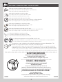
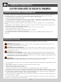
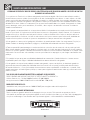
**IMPORTANT SAFETY INFORMATION**
• Place the equipment on a level, well-drained ground, not less than 6.6 ft (2.0 m) from any structure or obstruction such
as a fence, garage, house, overhanging branches, laundry lines, or electrical wires
• Provide enough room so that children can use the equipment safely.
• Separate active and quiet activities from each other.
• To prevent serious injury, warn children that they must not use the equipment until properly installed.
• Create a site free of obstacles that could cause injuries – such as low overhanging tree branches, overhead wires, tree
stumps and/or roots, large rocks, bricks, and concrete.
• Choose a level location for the equipment. This can reduce the likelihood of the Playhouse tipping over.
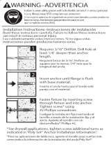
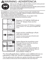
• When tightening any hardware, ensure the parts that are being secured leave a gap of less than 3/16” (4.76 mm) to
eliminate safety concerns.
• This Playhouse uses two AAA (1.5 V) batteries. Replace when necessary.
• Do not mix old and new batteries
• Do not mix alkaline, standard (carboz-zinc), or rechargable batteries.
• Only use the batteries specifi ed by the manufacturer.
• For any questions call our Customer Service Department at 1-800-225-3865 for more information.
INSTALLATION & GROUND PREPARATION INSTRUCTIONS
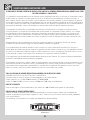
OPERATING INSTRUCTIONS
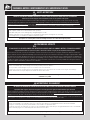
Observing the following instructions and warnings reduces the likelihood of serious or fatal injury:
• The maximum number of occupants that may safely use the entire Playhouse including all components is six.
• On-site adult supervision should be provided for children of all ages
• Do not let children climb onto the roof.
• Do not move the equipment while it is in use.
• Instruct children not to use the equipment in a manner other than intended.
• To prevent entanglement and strangulation, dress children appropriately using well-fi tting shoes and avoiding ponchos,
scarves, jackets with neck drawstrings, cord-connected items, helmets with straps, and other loose-fi tting clothing that is
potentially hazardous while using equipment. These items can cause death by strangulation.
• Instruct children not to play when the equipment is wet.
• Dress children with well-fi tting and full foot enclosing footwear. Examples of inappropriate foot ware are clogs, fl ip fl ops, and
sandals.
• Instruct children to remove their bike or other sports helmet before playing in the Playhouse equipment. These items can cause
death by strangulation.
PLEASE READ BEFORE BEGINNING ASSEMBLY:
!
WARNING: CHOKING HAZARD - Small parts. Sharp points. Not for children under 3 yrs. Adult assembly required.
!
WARNING: Instruct children not to attach items to the Playhouse equipment that are not specifi cally designed for
use with the equipment, such as, but not limited to, jump ropes, clothesline, pet leashes, cables and chain as
they may cause a strangulation hazard.
!
WARNING: Always check the temperature of the product before letting children play on it.
Remember that the product may cause burns if left in direct sunlight.
Always be aware of the sun and weather conditions and do not assume that the equipment is safe because the
air temperature is not very high.
!
WARNING: This Playhouse requires an anchor system, which is provided for grass/dirt. Customer must provide
anchors for any other surface. DO NOT use this Playhouse without the anchor system being installed. Adult
assembly required.
Page is loading ...
Page is loading ...

9
ZONE DE SÉCURITÉ — Placez l’équipement à plus de 2,0 m (6.6 pi) de toute structure ou obstruction
telle qu’une clôture, un garage, une maison, des branches basses, des cordes à linge ou des fils
électriques.
ZONA DE SEGURIDAD — Coloque el equipo a no menos de 2.0 m (6.6 pies) de cualquier estructura u
obstrucción como una cerca, una cochera, una casa, ramas que cuelgan, lazos para tender ropa o cables
eléctricos.
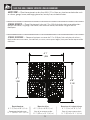
SAFE PLAY AREA / ZONE DE SÉCURITÉ / ZONA DE SEGURIDAD
SAFETY ZONE — Place the equipment no less than 6.6 ft. (2.0 m) from any structure or obstruction such
as a fence, garage, house, overhanging branches, laundry lines, or electrical wires.
Dimensions du Jeu:
6' 1" (1,9 m) x 6' 8" (2,1 m)
Aire de jeu recommandée:
12' 7" (3,9 m) x 13' 1" (4,1 m)
Dimensiones del conjunto de juegos
6' 1" (1,9 m) x 6' 8" (2,1 m)
Área de juego recomendada
12' 7" (3,9 m) x 13' 1" (4,1 m)
Playset dimensions:
6' 1" (1,9 m) x 6' 8" (2,1 m)
Recommended play area:
12’ 7" (3,9 m) x 13' 1" (4,1 m)
6’ 1”
1,9M
6’ 1”
1,9M
6’ 8”
2,1M
Page is loading ...

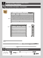
11
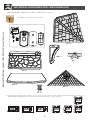
HARDWARE REQUIRED / QUINCAILLERIE REQUIS / HERRAJE REQUERIDO
LOWER WALLS ASSEMBLY / ASSEMBLAGE DES MURS INFÉRIEURS /
ENSAMBLAJE DE LAS PAREDES INFERIORES
1
Hardware Blister Pack / Blister des quincaillerie / Blíster de herraje
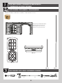
PARTS REQUIRED / PIÈCES REQUISES / PIEZAS REQUERIDAS
CONTENTS OF BOX 1 / CONTENU DE LA BOÎTE 1 / CONTENIDO DE LA CAJA 1
GFQ (x5)
GFR (x5)
GFS (x5)
GFT (x12)
GFY (x4)
GIA (x1)
GGG
GHS (x1)
GHQ (x1)
GLV (x1)
CHK (x5)
GFV (x4)
GGB (x4)
GHR (x2)
GIP (x1)
GIQ (x2)
GIO (x1)
GHP (x1)
GGT (x1)
GBX (x4)
GLD
Parts Bag / Sac de pièces / Bolsa de piezas
The anchors supplied are for grass/dirt only.
Les ancres fournies ne concernent que l’herbe/la terre.
Las anclas proporcionadas son adecuadas sólo para
pasto/tierra.

12
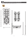
TOOLS REQUIRED / OUTILS REQUIS / INSTRUMENTAL REQUERIDO
1
PARTS REQUIRED / PIÈCES REQUISES / PIEZAS REQUERIDAS
CONTENTS OF BOX 2 / CONTENU DE LA BOÎTE 2 / CONTENIDO DE LA CAJA 2
GGO (x1)
(1)
(1)
5/16" ≈8 mm
(1)
GGR (x2)
(1)
LOWER WALLS ASSEMBLY / ASSEMBLAGE DES MURS INFÉRIEURS /
ENSAMBLAJE DE LAS PAREDES INFERIORES
GHA (x3)
GHD (x1) GHE (x1)
GGZ (x4)
(1)
Page is loading ...

14
TOOLS AND HARDWARE REQUIRED / OUTILS ET QUINCAILLERIE REQUIS / INSTRUMENTAL Y HERRAJE REQUERIDOS
X SECTION 1 (CONTINUED) / SECTION 1 (SUITE) / SECCIÓN 1 (CONTINUACIÓN)
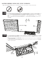
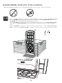
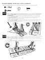
1.2
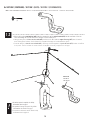
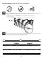
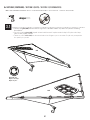
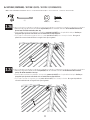
• When placing the round steel bar (GGZ), hold the narrow side of the anchor bracket (GFY) into the wall hole. Slide the
steel bar through the anchor bracket securing the bracket into place.
• Lorsque vous placez la barre en acier ronde (GGZ), maintenez le côté étroit du support d’ancrage (GFY) dans le trou du
mur. Faites glisser la barre d’acier à travers le support d’ancrage en le maintenant en place.
• Cuando coloque la barra de acero redonda (GGZ), mantenga el lado angosto del soporte del ancla (GFY) dentro del orifi cio
de la pared. Deslice la barra de acero a través del soporte del ancla y asegúrelo en su lugar.
GGZ
GFY
GFY
GGZ
GFY (x1)
Narrow side
Côté étroit
Lado angosto
(1)
• An anchor system is required. See Safety
Information sheet on page 6.
• Un système d’ancrage est requis. Voir la fi che
d’informations de sécurité à la page 7.
• Se requiere un sistema de anclas. Revise la hoja
de información en la página 8.
!
Page is loading ...

16
TOOLS AND HARDWARE REQUIRED / OUTILS ET QUINCAILLERIE REQUIS / INSTRUMENTAL Y HERRAJE REQUERIDOS
X SECTION 1 (CONTINUED) / SECTION 1 (SUITE) / SECCIÓN 1 (CONTINUACIÓN)
6
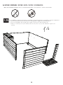
1.5
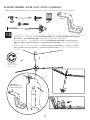
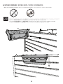
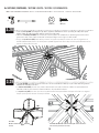
• Repeat steps 1.1 - 1.4 to attach the third interlock wall panel (GHA) with the round steel bar (GGZ), anchor bracket (GFY),
anchor (GBX) and anchor mount bracket (GGB). Leave the anchor on the outside of the walls.
• Répétez les étapes 1.1 - 1.4 pour attacher le troisième panneau mural interconnecté (GHA) à la barre d’acier ronde
(GGZ), ancre (GBX) au support d’ancrage (GFY) et au support de fi xation d’ancrage (GGB). Laissez l’ancre à l’extérieur des
murs.
• Repita los pasos 1.1 - 1.4 para sujetar el tercer panel de pared que se engancha (GHA) con la barra de acero redonda
(GGZ), ancla (GBX) el soporte del ancla (GFY) y el soporte de montaje del ancla (GGB). Deje el ancla en la parte externa de
las paredes.
GHA
GGZ
GFY
GFY
GGZ
GFY (x1)
Narrow side up
Côté étroit vers le haut
Lado angosto hacia arriba
GGB
GFV
(1)
(1)
GFV (x1)
GGB (x1)
GBX (x1)
GBX
• Repeat this step.
• Répétez cette étape.
• Repita este paso.
(1)

17
TOOLS AND HARDWARE REQUIRED / OUTILS ET QUINCAILLERIE REQUIS / INSTRUMENTAL Y HERRAJE REQUERIDOS
X SECTION 1 (CONTINUED) / SECTION 1 (SUITE) / SECCIÓN 1 (CONTINUACIÓN)
6
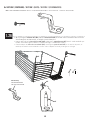
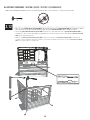
1.6
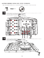
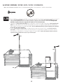
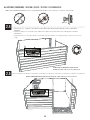
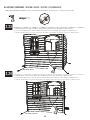
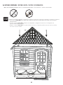
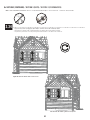
• Drill holes in the second and third walls in the locations shown. When drilling the holes, always use
the dimples provided in the walls. The sink will be attached on the other side of the walls.
• Percez des trous dans les deuxième et troisième murs aux emplacements indiqués. Lors du perçage
des trous, utilisez toujours les empreintes prévues dans les murs. L’évier sera fi xé de l’autre côté des
murs.
• Taladre orifi cios en la segunda y la tercera pared en los lugares que se indica. Cuando taladre los
orifi cios, use siempre los orifi cios que vienen marcados en las paredes. El fregadero se colocará en el
otro lado de las paredes.
(1)
(1)
1
2
3

18
TOOLS AND HARDWARE REQUIRED / OUTILS ET QUINCAILLERIE REQUIS / INSTRUMENTAL Y HERRAJE REQUERIDOS
X SECTION 1 (CONTINUED) / SECTION 1 (SUITE) / SECCIÓN 1 (CONTINUACIÓN)
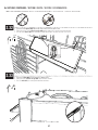
1.7
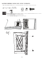
• Drill two holes in the sink pedestal (GHS) in the locations indicated.
• Percez deux trous dans la base de l’évier (GHS) aux emplacements indiqués.
• Taladre dos orifi cios en el pedestal del fregadero (GHS) en los lugares indicados.
(1)
(1)
Drill here
Percez ici.
Taladre aquí.

19
TOOLS AND HARDWARE REQUIRED / OUTILS ET QUINCAILLERIE REQUIS / INSTRUMENTAL Y HERRAJE REQUERIDOS
X SECTION 1 (CONTINUED) / SECTION 1 (SUITE) / SECCIÓN 1 (CONTINUACIÓN)
1.7
1.8
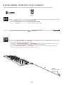
• Drill the following 12 holes through the bottom of the sink (GHP).
• Percez les 12 trous suivants dans le fond de l’évier (GHP).
• Taladre los siguientes 12 orifi cios en el fondo del fregadero (GHP).
1.7
1.9
• Drill the following holes through the back side of the sink (GHP).
• Percez les trous suivants à l’arrière de l’évier (GHP).
• Taladre los siguientes orifi cios en la parte posterior del fregadero (GHP).
GHP
(1)
(1)
GHP

20
TOOLS AND HARDWARE REQUIRED / OUTILS ET QUINCAILLERIE REQUIS / INSTRUMENTAL Y HERRAJE REQUERIDOS
X SECTION 1 (CONTINUED) / SECTION 1 (SUITE) / SECCIÓN 1 (CONTINUACIÓN)
1.7
1.10
• Drill the following hole through the Right-hand side of the sink (GHP). Drill one hole at the bottom of the sink.
• Percez le trou suivant dans le côté droit de l’évier (GHP). Percez un trou au bas de l’évier.
• Taladre el siguiente orifi cio en el lado derecho del fregadero (GHP). Taladre un orifi cio en el fondo del fregadero.
(1)
(1)
GHP
GHS
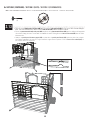
1.11
• Place the sink pedestal (GHS) against the third wall. Line it up with the two vertical holes drilled in the previous step.
• Placez la base de l’évier (GHS) contre le troisième mur. Alignez-la avec les deux trous verticaux percés à l’étape
précédente.
• Coloque el pedestal del fregadero (GHS) contra la tercera pared. Colóquelo en línea con los dos orifi cios verticales
que taladró en el paso anterior.
1
2
3

21
TOOLS AND HARDWARE REQUIRED / OUTILS ET QUINCAILLERIE REQUIS / INSTRUMENTAL Y HERRAJE REQUERIDOS
X SECTION 1 (CONTINUED) / SECTION 1 (SUITE) / SECCIÓN 1 (CONTINUACIÓN)
GHS
1.12
• Attach sink pedestal (GHS) with the hardware indicated.
• Fixez la base de l’évier (GHS) avec la quincaillerie indiquée.
• Sujete el pedestal del fregadero (GHS) con los elementos indicados.
GFS
GFS
GFR
GFR
GFQ
GFQ
GFQ (x2)
GFR (x2)
GFS (x2)
5/16" (≈8 mm)
(1)
(1)
(1)
Page is loading ...
Page is loading ...

24
TOOLS AND HARDWARE REQUIRED / OUTILS ET QUINCAILLERIE REQUIS / INSTRUMENTAL Y HERRAJE REQUERIDOS
X SECTION 1 (CONTINUED) / SECTION 1 (SUITE) / SECCIÓN 1 (CONTINUACIÓN)
1.7
1.16
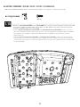
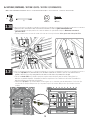
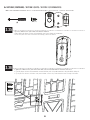
• Slide the faucet handles (GIQ) and the faucet (GIP) through the faucet base (GIO) as shown below.
• Faites glisser les poignées de robinet (GIQ) et le robinet (GIP) à travers la base du robinet (GIO) comme indiqué
ci-dessous.
• Deslice las manijas de la llave (GIQ) y el fregadero (GIP) a través de la base del fregadero (GIO) como se muestra a
continuación.
GIQ
GIQ
GIQ
GIP
GIP
GIQ
GIQ
GIP
GIO
GIO
GIO
GIO
1
2
3
4
5
6
Correct placement of nodules / Placement correct des
nodules / Colocación correcta de los nódulos

25
TOOLS AND HARDWARE REQUIRED / OUTILS ET QUINCAILLERIE REQUIS / INSTRUMENTAL Y HERRAJE REQUERIDOS
X SECTION 1 (CONTINUED) / SECTION 1 (SUITE) / SECCIÓN 1 (CONTINUACIÓN)
1.7
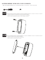
1.17
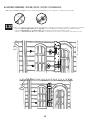
• Line up the Nodules in the faucet (GIP) and handles (GIQ) with the recesses in the sink shown below.
• Alignez les Nodules dans le robinet (GIP) et les poignées (GIQ) avec les trous de l’évier illustré ci-dessous.
• Alinee los nódulos en el fregadero (GIP) y las manijas (GIQ) con los orifi cios en el Fregadero que se muestran a
continuación.
GIQ
GIP
Nodules / Nodules / Nódulos
Recessions / Trous / Orifi cios
GIQ
• Attach the faucet (GIP) and handles (GIQ) to the sink by screwing in the hardware indicated from below the sink. Do
not over-tighten the screws!
• Fixez le robinet (GIP) et les poignées (GIQ) à l’évier en vissant la quincaillerie indiquée sous l’évier. Ne serrez pas trop
les vis!
• Sujete el grifo (GIP) y las manijas (GIQ) al fregadero atornillándolos en el equipo como se indica por debajo del
fregadero. ¡No apriete demasiado los tornillos!
GFT
GFT
GFT
GFT
GFT
GFT
1.7
1.18
GFT (x6)
(1)
(1)

26
TOOLS AND HARDWARE REQUIRED / OUTILS ET QUINCAILLERIE REQUIS / INSTRUMENTAL Y HERRAJE REQUERIDOS
X SECTION 1 (CONTINUED) / SECTION 1 (SUITE) / SECCIÓN 1 (CONTINUACIÓN)
1.7
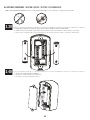
• Place the sink (GHP) onto the sink pedestal (GHS) and then slide it toward the wall into a locked position.
• Placez l’évier (GHP) sur la base de l’évier (GHS), puis faites-le glisser vers le mur en position verrouillée.
• Coloque el fregadero (GHP) en el pedestal del fregadero (GHS) y luego deslícelo hacia la pared hasta una posición de
bloqueo.
1.19
1.7
• Attach the sink (GHP) to the walls with the hardware indicated. This step requires two people.
• Fixez l’évier (GHP) aux murs avec la quincaillerie indiquée. Cette étape requière deux personnes.
• Fije el fregadero (GHP) a las paredes con los elementos indicados. Este paso requiere de dos personas.
1.20
GFR
GFR
GFR
GFQ
GFQ
GFQ
GFS
GFS
GFS
(1)
GFQ (x3)
GFR (x3)
GFS (x3)
(1)
(1)
5/16" ≈8 mm
Page is loading ...

28
TOOLS AND HARDWARE REQUIRED / OUTILS ET QUINCAILLERIE REQUIS / INSTRUMENTAL Y HERRAJE REQUERIDOS
X SECTION 1 (CONTINUED) / SECTION 1 (SUITE) / SECCIÓN 1 (CONTINUACIÓN)
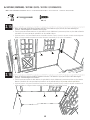
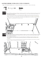
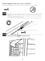
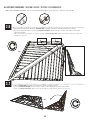
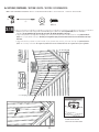
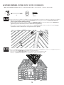
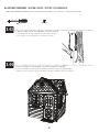
1.23
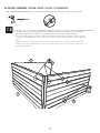
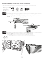
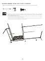
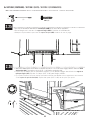
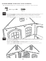
• Slide the front wall lower panels (GHD and GHE) over the wall support tube (GGO) and snug them up to the step (GGT).
• Faites glisser les panneaux muraux inférieurs avant (GHD et GHE) sur le tube de support mural (GGO) et fi xez-les à la marche
(GGT).
• Deslice los paneles inferiores de la pared frontal (GHD y GHE) sobre el tubo de soporte de la pared (GGO) y ajústelos hasta el
escalón (GGT).
GHD
GHE
GGO
GGT
1.24
• The front wall lower panels (GHD and GHE) will cover the fi rst and third holes, while the step (GGT) will cover the second
hole.
• Les panneaux muraux inférieurs avant (GHD et GHE) couvriront les premier et troisième trous, tandis que la marche (GGT)
couvrira le deuxième trou.
• Los paneles inferiores de la pared frontal (GHD y GHE) cubrirán el primer y el tercer orifi cio, mientras que el escalón (GGT)
cubrirá el segundo orifi cio.
First hole
Premier trou
Primer orifi cio
Second hole
Deuxième trou
Segundo orifi cio
Third hole
Troisième trou
Tercer orifi cio

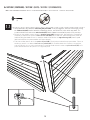
29
TOOLS AND HARDWARE REQUIRED / OUTILS ET QUINCAILLERIE REQUIS / INSTRUMENTAL Y HERRAJE REQUERIDOS
X SECTION 1 (CONTINUED) / SECTION 1 (SUITE) / SECCIÓN 1 (CONTINUACIÓN)
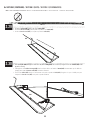
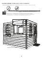
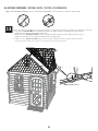
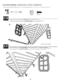
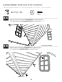
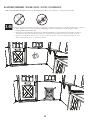
1.25
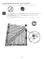
• Place the front wall assembly next to the three standing walls. Engage the interlocking corners.
• Placez le mur frontal à côté des trois murs debout. Enclenchez les coins interconnectés.
• Coloque el ensamblaje de la pared frontal junto a las tres paredes que ya están montadas. Enganche las
esquinas.

30
TOOLS AND HARDWARE REQUIRED / OUTILS ET QUINCAILLERIE REQUIS / INSTRUMENTAL Y HERRAJE REQUERIDOS
X SECTION 1 (CONTINUED) / SECTION 1 (SUITE) / SECCIÓN 1 (CONTINUACIÓN)
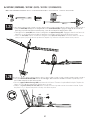
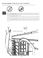
1.26
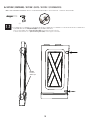
• When placing the round steel bars (GGZ), hold the anchor bracket (GFY) in the wall channel so that the round steel bar
slides through the anchor bracket, securing the bracket into place.
• Lorsque vous placez les barres d’acier rondes (GGZ), maintenez le support d’ancrage (GFY) dans le canal mural afi n que
la barre d’acier ronde glisse à travers le support d’ancrage, le maintenant en place.
• Cuando coloque las barras de acero redondas (GGZ), mantenga el soporte del ancla (GFY) en el canal de la pared, de
modo que la barra de acero redonda se deslice entre el soporte del ancla y lo asegure en su lugar.
GFY
GGZ
GGZ GGZ
Narrow side up
Côté étroit vers le haut
Lado angosto hacia arriba
GFY (x2)
(1)
Page is loading ...
Page is loading ...
Page is loading ...
Page is loading ...

35
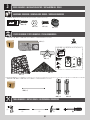
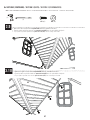
2
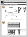
PARTS REQUIRED / PIÈCES REQUISES / PIEZAS REQUERIDAS
GGQ (x2)
CONTENTS OF BOX 2 / CONTENU DE LA BOÎTE 2 / CONTENIDO DE LA CAJA 2
CONTENTS OF BOX 1 / CONTENU DE LA BOÎTE 1 / CONTENIDO DE LA CAJA 1
GGM (x2)
GHA (x1)
GHB (x2)
* This panel is pre-drilled in the locations
listed / Ce panneau est pré-percé aux
endroits indiqués / Este panel viene ya
taladrado en los lugares mencionados
UPPER WALLS ASSEMBLY / ASSEMBLAGE DES MURS SUPÉRIEURS
/ ENSAMBLAJE DE LAS PAREDES SUPERIORES
GHM (x4)
GGY (x6)
GFP (x1)
GGV (x2)
GGU (x2)
GHF (x2)
Page is loading ...
Page is loading ...
Page is loading ...
Page is loading ...
Page is loading ...
Page is loading ...
Page is loading ...
Page is loading ...
Page is loading ...
Page is loading ...
Page is loading ...
Page is loading ...
Page is loading ...
Page is loading ...
Page is loading ...
Page is loading ...
Page is loading ...
Page is loading ...
Page is loading ...
Page is loading ...
Page is loading ...
Page is loading ...
Page is loading ...
Page is loading ...
Page is loading ...
Page is loading ...
Page is loading ...
Page is loading ...
Page is loading ...
Page is loading ...
Page is loading ...
Page is loading ...
Page is loading ...
Page is loading ...
Page is loading ...
Page is loading ...
Page is loading ...
Page is loading ...
Page is loading ...
Page is loading ...
Page is loading ...
Page is loading ...
Page is loading ...
Page is loading ...
Page is loading ...
Page is loading ...
Page is loading ...
Page is loading ...
Page is loading ...
Page is loading ...
Page is loading ...
Page is loading ...
Page is loading ...
Page is loading ...
Page is loading ...
Page is loading ...
Page is loading ...
Page is loading ...
Page is loading ...
Page is loading ...
Page is loading ...
Page is loading ...
Page is loading ...
Page is loading ...
Page is loading ...
Page is loading ...
Page is loading ...
Page is loading ...
Page is loading ...
-
 1
1
-
 2
2
-
 3
3
-
 4
4
-
 5
5
-
 6
6
-
 7
7
-
 8
8
-
 9
9
-
 10
10
-
 11
11
-
 12
12
-
 13
13
-
 14
14
-
 15
15
-
 16
16
-
 17
17
-
 18
18
-
 19
19
-
 20
20
-
 21
21
-
 22
22
-
 23
23
-
 24
24
-
 25
25
-
 26
26
-
 27
27
-
 28
28
-
 29
29
-
 30
30
-
 31
31
-
 32
32
-
 33
33
-
 34
34
-
 35
35
-
 36
36
-
 37
37
-
 38
38
-
 39
39
-
 40
40
-
 41
41
-
 42
42
-
 43
43
-
 44
44
-
 45
45
-
 46
46
-
 47
47
-
 48
48
-
 49
49
-
 50
50
-
 51
51
-
 52
52
-
 53
53
-
 54
54
-
 55
55
-
 56
56
-
 57
57
-
 58
58
-
 59
59
-
 60
60
-
 61
61
-
 62
62
-
 63
63
-
 64
64
-
 65
65
-
 66
66
-
 67
67
-
 68
68
-
 69
69
-
 70
70
-
 71
71
-
 72
72
-
 73
73
-
 74
74
-
 75
75
-
 76
76
-
 77
77
-
 78
78
-
 79
79
-
 80
80
-
 81
81
-
 82
82
-
 83
83
-
 84
84
-
 85
85
-
 86
86
-
 87
87
-
 88
88
-
 89
89
-
 90
90
-
 91
91
-
 92
92
-
 93
93
-
 94
94
-
 95
95
-
 96
96
-
 97
97
-
 98
98
-
 99
99
-
 100
100
-
 101
101
-
 102
102
-
 103
103
-
 104
104


Ask a question and I''ll find the answer in the document
Finding information in a document is now easier with AI
in other languages
Related papers
-
Lifetime 290980 Owner's manual
-
-
-
-
-
Lifetime 90952 Owner's manual
-
-
Lifetime 90951 Owner's manual
-
-
Other documents
-
Giant GFR Series User manual
-
Coyote C1EL120SM Operating instructions
-
Polk Audio Command Bar Installation guide
-
Moen YB8088CH Owner's manual
-
APPS GVT Stream User guide
-
 Red Head 35220 Installation guide
-
 Red Head 35225 Installation guide
-
Ferplast 57065070 User manual
-
 Canadian Playhouse Factory LAC66D Operating instructions
-
Suncast CC100 Operating instructions


