Page is loading ...

HEATING
FURNACES
Form No. 31315 07/18 | ©2018 Dometic Corporation
AFS/DFS, AFM/DFM, AFL/DFL, 79/80, 85/89
EN
DF Series Furnaces
Service Manual

2
EN
Furnaces
NORTH AMERICAN ADDRESS INFORMATION
U.S.A. & CANADA
Service Office
Dometic Corporation
1120 North Main Street
Elkhart, IN 46514
Service Center & Dealer Locations
Visit: www.dometic.com
CONTENTS
1 Explanation of symbols and safety instructions ................................................ 2
2 Intended use ........................................................................... 3
3 Operational issues and diagnostics ......................................................... 4
4 General information ..................................................................... 6
5 Diagnostic procedures .................................................................. 18
6 Heating Issues ......................................................................... 26
7 Service procedures .....................................................................30
8 Maintenance .......................................................................... 41
9 Disposal ..............................................................................43
10 Appendix A: Supplemental bulletins .......................................................44
1 EXPLANATION OF SYMBOLS AND SAFETY INSTRUCTIONS
This manual has safety information and instructions to help you eliminate or reduce the risk of accidents and injuries.
1.1 Recognize safety information
This is the safety alert symbol. It is used to alert you to potential physical injury hazards. Obey all safety
messages that follow this symbol to avoid possible injury or death.
1.2 Understand signal words
A signal word will identify safety messages and property damage messages, and will indicate the degree or level
of hazard seriousness.
indicates a hazardous situation that, if not avoided, could result in death or serious injury.
indicates a hazardous situation that, if not avoided, could result in minor or moderate injury.
is used to address practices not related to physical injury.
I
indicates additional information that is not related to physical injury.

3
EN
Furnaces
1.3 Supplemental directives
Read and follow all safety information and instructions to avoid possible injury or death.
Read and understand these instructions before service or maintenance of this product.
Incorrect service or maintenance of this product can lead to serious injury.
The installation must comply with all applicable local or national codes, including the latest edition of the
following standards:
U.S.A.
• ANSI/NFPA70, National Electrical Code (NEC)
• ANSI/NFPA 1192, Recreational Vehicles Code
Canada
• CSA C22.1, Parts l & ll, Canadian Electrical Code
• CSA Z240 RV Series, Recreational Vehicles
1.4 General safety messages
Failure to obey the following warnings could result in death or serious injury:
• SERVICE HAZARD:
– Installation, repairs and preventative maintenance should be done by a qualified service person only.
– The furnace should be inspected before use and at least annually, by a qualified service person only.
• HIGH TEMPERATURE HAZARD:
– Do not touch or put combustibles on or near the furnace.
– Supervise young children in the same room as the furnace.
• CARBON MONOXIDE POISONING HAZARD. Improper installation, adjustment, alterations, service, or
maintenance can cause death or serious injury.
• ELECTRICAL HAZARD:
– Label all wires prior to disconnection when servicing. Wiring errors can cause improper and dangerous
operation. Verify proper operation aer servicing.
– Do not use 120 VAC current with DC models.
• HAZARDOUS WASTE HAZARD. Some old thermostats may contain mercury. Handle with care. Dispose of
properly.
• ELECTRICAL SHOCK, FIRE, EXPLOSION, AND/OR CARBON MONOXIDE HAZARD.
– Use only Dometic replacement parts and components, which are specifically approved for use with the
Furnace.
– Disconnect electricity to the appliance before installation or service.
– Do not cause a short in the control terminals of the appliance.
– Wiring must conform to local codes and ordinances.
I
When appliances have time-delay controls, the system’s operation will lag behind the thermostat’s call for
heat.
2 INTENDED USE
This service manual is intended for use by OEM installers and dealer technicians. It is not intended for use by RV
owners, or those unfamiliar with the workings of furnaces used in the RV industry.
Manual users are assumed to have a basic understanding of RV HVAC best practices and experience in the
proper use of the tools and materials related to installing, operating, maintaining, and servicing of HVAC
equipment used in the RV industry.

4
EN
Furnaces
3 OPERATIONAL ISSUES AND DIAGNOSTICS
This section has tables showing the main causes for furnace issues. The Operational Issues table helps you
identify a range of furnace operational issues and the potential servicing solutions associated with those issues.
The Diagnostics table links specific furnace components to the diagnostic tasks associated with that component.
Remember to check the basics before replacing any parts, such as loose wiring and overall heating issues. Refer
to the Maintenance (on page 41) and Heating Issues (on page 26) sections for more detail.
Review the operational issues table for a list of potential operational issues, possible solutions, and servicing
procedure links. Refer to the Diagnostics Table (on page 5) for links to specific diagnostic information on the
furnace components, for confirmation of the operational issue.
Operational Issues Table
Operational Issue
Potential Reason
Page
Motor does not run
Defective motor
36
Defective external relay
37
Fan motor runs but no spark
Low DC voltage
26
Defective circuit board or ignitor on the circuit board
32
Combustion wheel is loose
33
Electrode is defective or out of adjustment
34
Defective limit switch
35
Defective motor
36
Defective sail switch
38
Furnace sparks but does not ignite
Gas pressure issue
26
Defective circuit board
32
Electrode is defective or out of adjustment
34
Defective gas valve
39
Orifice issue
39
Motor vibrates or is noisy
Blower wheel is damaged
31
Blower wheel is dirty
41
Loose object inside the blower wheel
31
Motor mount is loose
36
Motor sha is damaged
36
Burner ignites then locks out
Low gas pressure
26
Defective circuit board
32
Combustion wheel is loose
33
Electrode is defective or out of adjustment
34
Furnace is limiting
Installation issue 26/see specific furnace installation instructions
Ducting issue 26/see specific furnace installation instructions
Return Air issue 26/see specific furnace installation instructions
Defective limit switch
35
Fan and burner turn off
Defective external relay
37

5
EN
Furnaces
Operational Issue
Potential Reason
Page
Thermostat is calling for heat – no
fan/no operation
Air conditioner board issue
18
DC voltage issue
26
Defective circuit board
32
Defective motor
36
Defective external relay
37
Defective sail switch
38
Fan runs continuously with
thermostat set to off
Defective circuit board/fan relay on board is stuck closed
32
Defective external relay
37
Visible buildup of soot
Gas pressure issue
26
Combustion wheel is loose
33
Defective motor
36
Defective gas valve
39
Orifice issue
39
Incorrect exhaust tube (AF model furnaces)
41
Circuit board is getting wet on the
AFM series furnace
Door installation issue 26/see specific furnace installation instructions
Circuit board is lying on the floor of the furnace
32
Diagnostics Table
Diagnostic Area Page Diagnostic Area Page
AC Board/Thermostats 18 Electrode 22
Blower Wheel 18 Limit Switch 22
Burner Head 19 Motor 23
Circuit Board 19 Relay 23
Circuit Breaker Switch 21 Sail Switch 24
Combustion Wheel 22 Solenoid/Gas Valve 25

6
EN
Furnaces
4 GENERAL INFORMATION
This section provides reference information on the tooling, model identification, components, operation, and
terminology associated with the different furnace models.
4.1 Tools and materials
Required Tools
U-tube manometer with 1/8" pipe nipple Incline manometer
Multimeter Circuit board tester
Air-speed indicator Long-handled Allen wrenches (9/64" and 1/8")
Leak-test solution 1/4" nut driver
Open-end wrenches Flat-blade screwdriver
Phillips screwdriver Safety glasses
Optional Tools and Materials
Flashlight Two pipe wrenches
Wire nuts (various sizes) Wire cutter
Wire stripper Electrical tape
Scissors or utility knife Metal duct tape
#8 Self-tapping sheet-metal screws Wire cleaning brush
Compressed air cannister Cleaning solution and towels
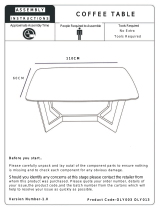
4.2 Model identification
Data/Model Tag
MODEL NO.
NUMERO DE MODÉLE
AFLD40111
INPUT BTU/HR
DÉBIT CALORIFIQUE
40,000
OUTPUT BTU/HR
CALORIFIQUE
30,400
MANIFOLD PRESSURE
PRESSION TUBULURE
10.0"
ORIFICE SIZE DIMENSION
DE L’INJECTEUR
49 DMS
TYPE OF GAS
ESPECE DE GAZ
PROPANE-LP
P/N STK 30312
1
Serial Number Tag
Item# 30000
SERIAL# 70000000
70000000
2

7
EN
Furnaces
AF/DF Series
DF M D 30 1 1 1
Rate Stages
Door Style
Type of Gas
BTU/hr Rating Model number example: DFMD30111
Voltage
Cabinet Size
Furnace Type
Furnace
Type
Cabinet
Size
Voltage BTU Rating
Type of
Gas
Door Style
Rate
Stages
DF = Dometic
Furnace S = Small
DC =
DC Voltage 12 = 12,000 35 = 35,000 1 = LP Gas
1 = Door 1 = Single
AF = Atwood
Furnace
SA = Small
Low Amps
(for small
furnaces
only)
AC =
AC Voltage 16 = 16,000 40 = 40,000
2 = LP or
Natural Gas
2 = No Door
20 = 20,000
3 = Door w/Rear Gas
Fitting
M = Medium 25 = 25,000
4 = Door w/
Connector
L = Large 30 = 30,000
5 = Door w/Rear Gas
Fitting & Connector
79/80, 85, 89 Series
85 35 DC LP IV
Version
Type of Gas
Voltage Model number example: 85-35 DCLP IV
BTU/hr Rating
Furnace Type
Furnace Type BTU Rating Voltage Type of Gas Version
79 = 7900 Series 12 = 12,000 31 = 31,000 DC = DC Voltage LP = LP Gas (no #) = Version 1
80 = 8000 Series 16 = 16,000 35 = 34,000 AC = AC Voltage LP/NAT = LP or Natural Gas II = Version 2
85 = 8500 Series 20 = 20,000 40 = 40,000 III = Version 3
89 = 8900 Series 25 = 25,000 IV = Version 4
85/89 Series Two-Stage
1522 DC LP
Type of Gas Model number example: 1522 DC LP
Voltage
Model
Model BTU Rating (low) BTU Rating (high) Voltage Type of Gas
1522 15,000 22,000 DC = DC Voltage LP = LP Gas
2334 23,000 34,000
2540 25,000 40,000

8
EN
Furnaces
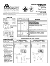
4.3 Component locations
AF/DF Series
3
Possible On/Off Switch/
Circuit Breaker Location
(LD Models)
Blower Wheel
Possible Sail Switch Location
Possible Sail Switch Location
Circuit Board
Possible On/Off Switch/
Circuit Breaker Location
Heat Exchanger
Combustion Wheel
Gas Valve
Limit Switch
79/80 Series
4
Blower Wheel
Electrode
Circuit Board
(back of plate)
Limit Switch
Combustion
Wheel
Sail Switch
(behind panel)
Gas Valve
Circuit Breaker Switch
Circuit Board
Plate (removed)
Directional
Louver
85/89 Series
5
Blower Wheel
Sail Switch
(inside Blower Wheel)
Limit Switch
(behind Blower Wheel)
External Relay
Circuit Breaker Switch
Combustion Wheel
Circuit Board
Gas Valve

9
EN
Furnaces
4.4 Sequence of operation/wiring diagrams
I
The wiring diagrams shown are the best representations of each furnace. Wire colors may vary.
Understanding the sequence of operations for a furnace is an important part of diagnosing the operational issues
occurring in the furnace. This section details the wiring and sequence of operation for each furnace type:
• DC Models (on page 9)
• AC Models (on page 12)
• Two-Stage Models (1522, 2334, and 2540) (on page 14)
DC Models
6
Limit Switch
Sail Switch
ON/OFF
Switch -
Breaker
Electrode
4-Pin Ground
Motor
Gas Valve
Ignition Control
Module
Blue
Red
Red
Red
Red
Red
BLO
PWR2
TH (pin)
AIR (pin)
GND (pin)
V1 (pin)
Red
Blue
Blue
Blue
Blue
+12 VDC
+Thermostat
-12 VDC
-Thermostat
Black
Black
Black
Black
Black

10
EN
Furnaces
7
Thermostat
Relay
Ignition Control
+12 VDC
Motor
Sail
Switch
Valve
Limit
Switch
Circuit
Breaker
On/Off Switch
(some furnaces have
combination On/Off
switch circuit breakers)
(Limit and Sail Switch are
reversed in 79/80 series)
I
This diagram shows the external relay used in furnaces built prior to 07/2001.
Sequence of operation for DC models (standard units):
1. The ON/OFF switch allows power to pass through the circuit breaker to the thermostat.
2. The thermostat controls the operating circuit to the furnace by reacting to room temperature. When room
temperature is below the thermostat set-point, the contact closes to allow current to flow to the relay (the
relay can be either external or part of the ignition control board).
3. The circuit breaker limits the amperage draw of the motor.
4. The relay allows current to pass to the motor by closing a switch within the relay. Voltage from the thermostat
activates the relay to turn the fan on. This takes 1–25 seconds. On units that have the relay on the
ignition control board, there is only a 1–2 second delay.
5. Current flows to the motor to operate the blower. One end of the motor sha is for the blower wheel, and the
other side is for the combustion wheel.
6. Circulating air blows against the sail switch and closes the contacts, completing the circuit. The sail switch is a
safety device that ensures airflow before ignition.
7. The limit switch is a safety device that protects the furnace from overheating. The contacts in the limit switch open
at a given temperature setting, shutting off power to the electronic ignition system that controls the gas valve. As
power is applied to the circuit board, the system does the following:
• A timing circuit allows the blower to purge the chamber (15–17 seconds).
• The circuit board supplies current to the gas valve and causes it to open. As the gas valve opens, the circuit
board sends a high-voltage spark to the electrode at the burner. The circuit board detects the presence of
a flame.
– If the flame is not sensed aer approximately six seconds, the valve will close and the chamber will be
purged of any gas. Aer three tries for ignition, the control will lock out for one hour, unless power is
removed or the thermostat has cycled. Shutting off the main power will restart the cycle.

11
EN
Furnaces
– If the system does not ignite and the thermostat remains closed on units with an external relay, the
blower will remain on until the thermostat is reset manually. Units with the relay on the ignition
control will shut the blower off even if the thermostat contacts remain closed. If the
thermostat is not reset within one hour, the system will try the ignition cycle again.
8. When the thermostat senses that the desired room air temperature contact is open, it will shut off power from
the ignition system and shut off the gas valve. The blower continues to run until the relay opens the circuit
(approximately 90 seconds), shutting off current to the motor.
I
On newer controls, a diagnostic error code light has been added. By counting the flashes of the light, an
error code can be determined. See the Code Failure Table for code failure information.
Code Failure Table
Number of Flashes
Diagnostic
Information
Explanation/Recommended Action
One (1) Flash with
Three-second (3) Pause
Airflow/Limit Fault Fan is running. No power is present at the air flow terminal
on the board. Potential cause are:
• Sail switch is not closing
• Limit switch is open
• Fan is not turning fast enough to close the sail switch
Check for voltage issues (see page 29) or a bad fan
motor (see page 23).
Two (2) Flashes with
Three-second (3) Pause
Flame Sense Fault The board is not sensing a flame.
Check for a faulty circuit board (see page 19) or a
defective electrode (see page 22).
Three (3) Flashes with
Three-second (3) Pause
Ignition Safety Lockout The furnace attempted ignition three times and failed to
light. The failed attempts caused a one-hour so safety
lockout of the furnace.
No Flashes, Steady Light Internal Control Failure Check for a faulty circuit board (see page 19).

12
EN
Furnaces
AC Models
8
Limit Switch
Sail Switch
Valve
ON/OFF
Switch
Electrode
Motor
Capacitor
Transformer
Ignition
Control
Blue
Blue
Red
Red
Red
Blue
Thermostat
Thermostat
Ground
120 VAC Hot
120 VAC Neutral
Blue
Blue
Black
Brown
Black
Black
Yellow
Green
Green
Green
White
White
White
White
Green
Green
Yellow
24 VAC
9
120 VAC input
120 VAC
(Older Models)
Circuit Breaker or
Breaker/Switch
Combination
ON/OFF Switch
Option
Ignition Control
Electrode
Limit
Switch
Sail Switch
Relay
Motor
Valve
Transformer
Thermostat
Capacitor

13
EN
Furnaces
Sequence of operation for AC models:
1. The transformer receives 120 VAC, which it converts to 24 VAC for the operating circuitry.
2. The thermostat controls the operating circuit to the furnace by reacting to room temperature. When room
temperature is below the thermostat set-point, the contacts close to allow current to flow to the relay (the
relay can be either external or part of the ignition control board).
3. The relay receives 24 VAC and energizes a heater coil within the relay. With relay-on-the-board models,
timing is controlled through the microprocessor. A bi-metal disc is activated and closes the relay circuit
(17–20 seconds). On controls with a built-in relay, there is only a 1–2 second delay.
4. Once the relay circuit is closed, 120 VAC flows to the motor to operate the blower. One end of the motor
sha is for the blower wheel and the other end is for the combustion wheel.
5. Circulating air blows against the sail switch and closes the contacts, completing the circuit. The sail switch is a
safety device that ensures airflow before ignition.
6. The limit switch is a safety device that protects the furnace from overheating. The contacts in the limit switch open at
a given temperature setting, shutting off power to the electronic ignition system that controls the gas valve.
7. As power is applied to the electronic ignition circuit board, the system does the following:
a. A timing circuit allows the blower to purge the chamber (15–17 seconds).
b. The circuit board supplies current to the gas valve and causes it to open. There is an electrical switch in-line
to the valve that allows power to be manually shut-off from the valve. This switch must be on for the furnace
to operate. The switch may be separate or combined with the circuit breaker.
c. As the gas valve opens, the circuit board sends a high-voltage spark to the electrode at the burner. The
circuit board detects the presence of a flame.
– If the flame is not sensed aer approximately six seconds, the valve will close and the chamber will be
purged of any gas. Aer three tries for ignition, the control will lock out for one hour, unless power is
removed or the thermostat has cycled. Shutting off the main power will restart the cycle.
– If the system does not ignite and the thermostat remains closed, the contacts open to shut off power
from the valve, which shuts off the gas. The blower will remain on until the heater coil within the relay
cools and the relay opens to stop the current flow to the motor. With relay-on-the-board models,
timing is controlled through the microprocessor.
I
On newer controls, a diagnostic error code light has been added. By counting the flashes of the light, an
error code can be determined. See the Code Failure Table for code failure information.
Code Failure Table
Number of Flashes Diagnostic Information
1 Low Input Voltage
2 Ignition Failure
3 Open High Limit
4 Stuck APS (Sail Switch)
5 Module Fault

14
EN
Furnaces
Two-Stage Models (1522, 2334, and 2540)
6 5 4 3 2 1
1 2 3 4 5
6
10
Electrode
Dual-
Control
Power
Switch
Limit
Switch
Sail
Switch
Circuit
Breaker
Motor
Ground
-12
VDC
+12
VDC
Low
Valve
Main
Valve
GV
Redundant
Valve
Thermostat
Case
Bulk
Head
Ignition
Control
5ON-12
Black
(Ground)
Orange
White
White
Black
Low
Valve
Ground
Ground
Ground
High
Voltage
Power to
High Valve
Power from
Thermostat
Power to Thermostat
Ground to Thermostat
Signal from Thermostat to Board
Power to
DSI Board
Power to
Motor
Power to On/
Off Switch
Power to
Board
I
The only compatible thermostat for the two-stage furnace is the Atwood digital thermostat (PN#38535).
Sequence of operation for two-stage models:
1. The digital thermostat controls the operating circuit to the furnace by reacting to room temperature. When
the room temperature is below the thermostat set-point by 2 °F, a heat-demand signal will be sent to the
controller module.
2. The ON/OFF switch is a safety device that shuts off power to the furnace ignition and gas valve systems.
3. The circuit breaker limits the amperage draw of the motor.
4. Current flows to the controller module and during the first seconds, the microprocessor confirms input and
verifies correct operation of safety redundancies. This module will perform the following diagnostic checks of
the system:
• Open sail switch
• Internal microprocessor faults
• Voltage inputs
• Ignition
• Open limit switch
In the event of a failure, an LED on the controller module will flash a code. On newer controls, a diagnostic
error code light has been added. By counting the flashes of the light, an error code can be determined. See
the Code Failure Table for code failure information.
5. The motor receives current from the controller module and will run at high speed or low speed, depending
on the demand signal the digital thermostat sends to the controller module. One end of the motor sha is for
the blower wheel and the other end is for the combustion wheel.

15
EN
Furnaces
6. Circulating air blows against the sail switch and closes the contacts, completing the circuit. The sail switch is a
safety device that ensures airflow before ignition.
7. The limit switch is a safety device that protects the furnace from overheating. The contacts in the limit switch
open at a given temperature setting, shutting off power. This activates the open limit switch diagnostics and
the LED on the controller module flashes, shutting down the gas valve. See the Code Failure Table for code
failure information.
8. As power is applied to the circuit board, the system does the following:
a. Timing circuits allow the blower to purge the heat chamber for 15 seconds.
b. When current is supplied to the gas valve, it opens to high-burn stage. The controller module activates the
low-burn operation on the valve.
c. As the valve opens, the ignition module sends a high-voltage spark to the electrode at the burner.
d. The ignition module detects the presence of a flame.
– If the flame is not sensed aer seven seconds of sparking, a signal is sent to the controller module that
there is no ignition and the controller module shuts off the gas valve.
– Aer another 24-second purge, the ignition module will try again.
– Aer a third try, the controller will go into a so safety lockout, timing for one hour, and the diagnostic
LED will flash a code. See the Code Failure Table for code failure information.
– Aer the timed hour, the controller will initiate three more tries for ignition. If there is no ignition, the
timing sequence begins again.
– If the system does not ignite and the thermostat is still calling for a heat demand, the blower will
continue to run for approximately 90 seconds as a post purge, then shut off. When the thermostat
senses the desired room air temperature, a signal is sent to the controller module to shut down
operation of the gas valve and run the blower for 90 seconds as a post purge of heat from the furnace
heat chamber.
Two-stage operation in automatic mode, when temperature is within 1 °F of the set-point of the thermostat, starts
the furnace in low-burn mode. If the temperature is above 1 °F of the set-point of the thermostat, the furnace will
start in high-burn mode. The thermostat can also be set to manual for either high or low modes. This will not
allow the unit to switch automatically with temperature changes.
Code Failure Table
Number of Flashes Diagnostic Information
1 Low Input Voltage
2 Ignition Failure
3 Open High Limit
4 Stuck APS (Sail Switch)
5 Module Fault

16
EN
Furnaces
4.5 General furnace terminology
Term Definition
AC Motor A motor operating on 120 VAC
Adjustable
Register
A heat outlet capable of being
opened and closed
Air Speed
Indicator
(Anemometer)
A tool used to measure the
velocity of air movement from a
duct outlet
Ambient Air
Temperature
Current room air temperature
Amp Draw
The amount of current required to
run a given component
Burn Off
The time it takes for the furnace
combustion chamber to burn
off all the oils and lubes used in
production
Burner
The component in the furnace
where combustion occurs,
creating the main source of heat
within the combustion chamber
Burner Flame
Li Off
When the flame lis off of the
burner
Candling
A small flame at the main burner
orifice when the valve is in a closed
position
Circuit Breaker
A normally closed switch
that automatically interrupts
an electrical circuit under an
abnormal Amp load
Circulating Air
Air drawn into the furnace by the
main air wheel then heated and
forced out the heat outlets
Combustion
Air
Air supplied to the burner
specifically for combustion
Combustion
Chamber
The component where
combustion occurs and transfers
heat to the circulating air
Converter
Component that is used to change
120 VAC to 12 VDC. Available
in linear, ferroresonant, and
switching styles
Cycling
The normal on and off operation
of the furnace as controlled by the
thermostat
DC Motor Motor operating on 12 VDC
Ignition Circuit
Board
A circuit board in the furnace
controlling the ignition sequence.
Evaluates whether a flame has
been established
Term Definition
Electrode
A conductor that establishes
an electrical spark at the burner
to ignite the air-to-gas mixture.
Senses and signals the circuit
board that a flame is established
Fan Switch
A normally open switch that
closes at a set temperature to
allow power flow to the motor.
Enables the motor to run aer the
burner shuts down to cool the
combustion chamber
Field Electrical
Hook-Up
The wiring harness that connects
the furnace to the coach wiring
Flair Fitting
Brass fitting used to connect the
furnace to the gas supply that has a
flared copper tube
Flashback
A condition created when the
flame burns back at the main
burner orifice
Flex Ducting
A round, collapsible,
wire-reinforced product used to
deliver the heated air from the
furnace to the living area
Forced
Combustion
The type of combustion created
when a second air wheel is used to
force air into the burner, increasing
the air-to-gas mixture
Gas Pressure
The amount of gas being supplied
to the furnace, measured in inches
of water column (W.C.)
Gas Valve
A mechanical device by which the
flow of gas is started or stopped by
an electrical signal
Gravity
Combustion
A type of combustion that
uses natural airflow to supply
combustion air to achieve the
proper air-to-gas mixture at the
burner
Hard Ducting
Ducting installed below the floor
line
Heat
Anticipator
Component of a thermostat that
can be adjusted to increase or
decrease the length of a heating
cycle
Heat
Exchanger
See combustion chamber
High-Tension
Lead Wire
The wire carrying the high-voltage
spark from circuit board to
electrode

17
EN
Furnaces
Term Definition
Incline
Manometer
Tool used to measure static
pressure of the furnace plenum
Junction Box
An enclosure inside the furnace
that houses wire connections
Limit Switch
A normally closed switch that
opens at a set temperature
to prevent the furnace from
overheating
Limiting
A condition where the burner
turns on and off rapidly. Caused by
overheating the limit switch
Loud Ignition
A condition where the burner
lights with a loud noise. Caused
when the air-to-gas mixture is
unbalanced or the spark gap is
incorrect
Main Burner
Orifice
The orifice regulating the amount
of gas delivered to the burner
Manifold
The piping that delivers gas from
the gas connection to the valve or
from the valve to the burner
Manual Reset
Switch
A limit switch requires a manual
reset aer a set temperature has
been reached
Micro-Amps
Current sent back to the circuit
board to establish the presence of
a flame at the main burner
Multi-Try Circuit
Board
A circuit board that runs two to
three trials for ignition
O.E.M.
“Original Equipment
Manufacturer.” A manufacturer of
recreational vehicles and parts
Pigtail See Field Electrical Hook-Up
Plenum
A enclosure that gathers air
and redirects it to specific
locations, like the box around the
combustion chamber
Power Supply
A source of electrical power;
usually a converter, inverter, or
battery
Primary Air
A portion of the combustion air
directed into the main burner
Resonating
A whining noise created by a
burner, air movement, or a blower
out of balance
Term Definition
Return Air
Air pulled into the furnace, heated,
and forced through duct outlets
into the living area
Safety Lockout
Caused when the circuit board
does not sense a flame and cuts
power to the gas valve
Sail Switch
Air-proving switch that engages
when the blower motor provides
enough air to close the switch
Secondary Air
Combustion air that is forced
around the burner to complete
combustion
Sensor Wire
Wire carrying an electrical signal
from the electrode back to the
circuit board on a remote-sense
system
Slope Gauge See incline manometer
Soot
A black powder created when
incomplete combustion occurs.
Normally found at an exhaust
opening
Start Capacitor
A device that gives an electrical
boost to the A/C motor during
start-up
Static Pressure
Amount of pressure inside the
furnace plenum or duct, caused by
the inability to dispel air from duct
outlets
Thermostat
Device used with the furnace to
sense and regulate the room air
temperature
Time-Delay
Relay
A normally open relay. When
activated, it closes to send power
to the blower motor. When
deactivated, it allows the blower to
run for a period of time to cool the
combustion chamber
Transformer
Device reducing 120 VAC to 24
VAC
U-Tube
Manometer
Tool measuring gas pressure in
inches of W.C.
Volt-Ohm
Meter (VOM)
Meter for reading voltage and
Ohm resistance
Valve Coil
Electromagnetic coil on the gas
valve that is used to open and
close the valve and start and stop
gas flow
>> Return to Operational Issues and Diagnostics

18
EN
Furnaces
5 DIAGNOSTIC PROCEDURES
ELECTRICAL SHOCK, FIRE, EXPLOSION, AND/OR CARBON MONOXIDE HAZARD. Use only
Dometic replacement parts and components, which are specifically approved for use with the Furnace. Failure to
obey this warning could result in death or serious injury.
This section has information to help you identify a range of furnace problems by diagnosing individual
component parts. Remember to check the basics before replacing any parts, such as loose wiring and overall
heating issues. Refer to the Maintenance (on page 41) and Heating Issues (on page 26) sections for more
detail.
Component Diagnostic Question Action Based On Status Page
Air Conditioner (AC) Board/Thermostats
ZONE
MODE
PROGRAM DEHUMIDIFY
OUTSIDE
TEMP
INSIDE
TEMP
°F / °CCLOCK
FAN
When the thermostat calls for
heat, does the relay on the AC
board close (to create continuity
and complete the circuit) and send
power to the thermostat terminal
on the furnace board (or external
relay depending on the model)?
When the thermostat is calling for
heat, check for continuity at the AC
control board or thermostat where
the two furnace wires connect. To
diagnose if the issue is with the
AC board/thermostat or with the
furnace, bypass the furnace wires at
the thermostat:
• If the furnace ignites and
heats, the problem is with the
thermostat or the AC control
board
• If the furnace does not run, the
problem is with the furnace
• If no continuity is present, the
AC board is bad and requires
replacement
Refer to the appropriate furnace
sequence of operation/wiring
diagrams to get error code details
9
I
Heat/Cool thermostats are commonly used with air conditioners
and Dometic furnaces. The warranty, installation instructions, and
diagnostic information are provided by the manufacturer of the
thermostat, and not by Dometic.
Blower Wheel
Inspect the blower wheel. Is the
blower wheel dirty (dust, pet hair,
etc.)?
Yes = Perform maintenance 41
Inspect the blower wheel. Is there
visible damage?
Yes = Replace the blower wheel 31
Is the blower wheel turning? No = Run tests on the motor 23
Is the blower vibrating or noisy? Yes =
• Confirm that there are no loose
objects (screws, etc.) within the
wheel
• Replace the blower wheel, if
necessary
31

19
EN
Furnaces
Component Diagnostic Question Action Based On Status Page
Burner Head
Inspect the burner head. Is
there visible damage (rust, burnt
through)?
Yes = Replace the burner head
• Determine the cause of the rust
and repair
• Check for improper combustion,
low gas pressure, or blockage.
Repair
31
Is excessive soot present? Yes =
• Confirm the burner head is
correct for the model and/or
BTU range of the furnace
• Blockage in heating chamber
or burner head. Perform
maintenance
• Check the exhaust tube to
confirm it is the correct one for
the furnace (AF models)
--
41
41
Is there a problem with the furnace
ignition?
Yes = Confirm the burner head is
correct for the model and/or
BTU range of the furnace
--
Does the burner ignite when the
blower is running?
No =
• Replace the burner head
• Burner head is obstructed.
Perform maintenance
31
41
Circuit Board
Are the system safety checks
operating properly?
No = Troubleshoot the individual
safety devices
--
Inspect the board. Are there visible
burns, brown streaks, melted
elements?
Yes = Replace the circuit board 32
Is there incoming power to the
circuit board?
No = Check that the circuit breaker
switch is in the on/reset
position
33

20
EN
Furnaces
Component Diagnostic Question Action Based On Status Page
Is there power at the thermostat
terminal on the board?
No =
• Confirm the thermostat is calling
for heat
• Confirm there is power at
the thermostat and at the air
conditioner control box
18
Is there power going out to the fan
motor?
No = Check the sail switch
• If the sail switch is stuck in the
closed position, replace the sail
switch
• If the sail switch is not stuck
in the closed position, check
the power at the thermostat
terminal and the air flow
terminal on the board. Replace
the board if you have proper
voltage at both terminals
38
Is there power at the air flow
terminal on the board?
No = Check for continuity
• If the limit switch is stuck open,
replace the limit switch
• If the sail switch is stuck open,
replace the sail switch
35
38
Is there power to the gas valve
from the circuit board within 15
seconds of power arriving at the
airflow terminal?
No =
Check the board. Replace if bad
Check the electrode for a short.
Replace if a short has occurred
32
34
Does the burner ignite then turn
off?
Yes = Verify that there are no
cracks in the ceramic on the
electrode, or any shorts in
the high-tension lead to the
electrode
34
Does the burner ignite when the
blower is running?
No=
• Improper ground.
Perform maintenance
• Edge connector or circuit board
is dirty. Perform maintenance
41
Is there an error light on the
control board?
Yes = Check the error codes for the
appropriate furnace in the
sequence of operation/wiring
diagrams
9
Is the gas valve opening but not
getting a spark?
Yes = Remove the electrode wire
from the ignitor. Hold the wire
close to the ignitor, using a pair
of insulated pliers. If it sparks,
replace the electrode
34
/