Page is loading ...

PSUPS20A12CR
v.1.1
PSUPS 13,8V/12V/20A/2x17Ah
Buffer power supply for up to 16 HD cameras and DVR
with recorder space
EN
Edition: 5 from 15.11.2017
Supercedes the edition: 4 from 22.09.2017
G
R
E
E
N
P
O
W
E
R
C
C
T
V

www.pulsar.pl PSUPS20A12CR
2
Features:
DC 13,8V uninterruptible power supply of HD cameras
DC 12V uninterruptible power supply of the recorder
fitting battery 2x17Ah/12V
recorder space
wide range of mains supply AC 176÷264V
built-in power factor correction system (PFC)
high efficiency 85%
16 outputs protected by 1A glass fuses for powering
cameras
12V/5A output dedicated to supply the recorder
battery charge and maintenance control
battery charging current 2A/4A/8A jumper selectable
(batteries 2x17Ah connect in parallel)
Approximate backup time: 2h
deep discharge battery protection (UVP)
battery output protection against short circuit
and reverse polarity connection
LED indication
protections:
SCP short-circuit protection
OLP overload protection
OVP over voltage protection
OHP overheat protection
surge protection
against sabotage
warranty – 2 years from the production date
An example of power supply for cameras.
CONTENTS:
1. Technical description.
1.1. General description
1.2. Block diagram
1.3. Description of PSU components and connectors
1.4. Specifications
2. Installation.
2.1. Requirements
2.2. Installation procedure
3. Operating status indication.
4. Operation and use.
4.1. Overload or short circuit of the PSU output (SCP activation)
4.2. Overload or short circuit of the recorder’s module or CCTV camera module
4.3. Battery-assisted operation
4.4. Parallel connection of batteries
4.5. Maintenance

www.pulsar.pl PSUPS20A12CR
3
1. Technical description.
1.1. General description.
A buffer PSU is intended for an uninterrupted supply to CCTV system devices requiring stabilized voltage of 12V
DC (+/-15%). The PSU has two circuits: first 1x5A/12VDC for supplying the recorder and 16x0,8A/13,8V DC for both
cameras. Current efficiency of the PSU amounts to:
1. Output current 16x0,8A + 5A recorder + 2A battery charging*
2. Output current 16x0,7A + 5A recorder + 4A battery charging*
3. Output current 16x0,4A + 5A recorder + 8A battery charging*
Total current of the receivers + battery 20A
*
max.
In case of 230V mains power loss, a battery back-up is activated immediately.
The approximate backup time is given assuming that all output ports are used (using typical devices and 34Ah
batteries). The electricity consumption for own needs and the energy efficiency of the power intake track were taken into
account. The exact description of how to perform the calculations can be found at: "Approximate backup time -
assumptions for calculations".
The power supply unit is placed in a metal enclosure (color RAL 9003) with space for 2x17Ah/12V batteries and a
recorder. The enclosure is equipped with a micro-switch indicating unwanted opening of the door (faceplate).
1.2. Block diagram (fig.1).
Fig.1. Block diagram of the PSU.
1.3. Description of PSU components.
Table 1. Description of components and connectors module LB8
Component no.
[Fig. 2]
Description
F1÷F8 glass fuses
L1÷L8 LED voltage indication at the outputs
AUX1 ÷ AUX8 independently protected outputs
IN1-, IN2- power supply inputs of the fuse module
*
See chart 1

www.pulsar.pl PSUPS20A12CR
4
Table 2. Description of components and connectors
Component no.
[Fig. 3]
Description
F
AUX
glass fuses
PE protection connector
AUX – output
IN – power supply inputs, output filter
The enclosure contains 2 fuse modules for powering 16 cameras.
Fig.2. The view of the fuse module LB8.
Fig.3. Output filter.
Table 3. Description of the module’s components and connectors.
Component no.
[Fig. 4]
Description
PSU module PSB-30012200
Connectors of the PSU:
L-N 230V/AC power connector, PE protection connector
V+, V- DC supply outputs
B+, B- battery output
green LED indicates DC power
P1 potentiometer, output voltage adjustment
Battery outputs: red: +, black: -
TAMPER, contact of tamper protection (NC)
Battery charging current selection:
Description: jumper on, jumper off
Fuse module LB8
DC/DC 50SE-SEP converter
Output filter
Cable for supplying recorder there is plug DC 2,1/5,5

www.pulsar.pl PSUPS20A12CR
5
Fig.4. The view of the PSU.

www.pulsar.pl PSUPS20A12CR
6
1.4. Specifications:
- electrical specifications (tab.4)
- mechanical specifications (tab.5)
- operation safety (tab.6)
- operating specifications (tab.7)
Table 4. Electrical specifications.
PSU type
A (EPS - External Power Source)
Mains supply
176÷264V AC / 50Hz
Current consumption
1,5A @230V AC
PSU’s power
264W
Efficiency
85%
Power factor PF
>0,95 @230V AC
Output voltage – Fuse base for fuse strips16x
Output voltage – recorder
11V÷ 13,8V DC – buffer operation
9,5V÷13,8V DC – battery-assisted operation
12V DC maintained regardless of the state of battery charge
Output current t
AMB
<30°C
16x0,8A + 5A recorder + 2A battery charging*
16x0,7A + 5A recorder + 4A battery charging*
16x0,4A + 5A recorder + 8A battery charging*
Total current of the receivers + battery 20A* max.
* see chart 1
Output current t
AMB
=40°C
16x0,4A + 5A recorder + 2A battery charging*
Total current of the receivers + battery 14A
*
max.
* see chart 1
Output voltage adjustment range
12÷14V DC
Ripple voltage
120mV p-p max.
PSU current consumption
0,3A
Battery charging current
(batteries 2x17Ah connect in parallel)
2A, 4A,8A jumper selectable
Approximate backup time
2h
Short-circuit protection SCP
2x STRIP LB8: 16x F 1A glass fuse,
Output filter 1xF 5A
Overload protection OLP
105% ÷ 150% of the PSU power, automatic recovery
Battery circuit protection SCP and reverse
polarity connection
glass fuse 30A
Surge protection
varistors
Over voltage protection OVP
>16V (activation requires disconnecting the load or supply for about
20 s.)
Deep discharge protection UVP
U<9,5V (± 5%) – disconnection of battery terminal
Sabotage protection:
- TAMPER output indicating enclosure opening
- micro-switches, NC contacts (enclosure closed),
0,5A@50V DC (max.)
Optical indication: front panel of the PSU
- AC OK.; LED indicating the AC power status
- AUX OK.; LED indicating the DC supply at
the PSU output
- red, normal status – on, failure: off
- green, normal status – on, failure: off
*
See chart 1

www.pulsar.pl PSUPS20A12CR
7
Table 5. Mechanical specifications.
Dimensions
W=420, H=535, D+D
1
=193+14 [+/- 2mm]
W
1
=425, H
1
=540 [+/- 2mm]
The dimensions of the
recorder compartment
W
2
=380, H
2
=320, D
2
=65 [+/- 2mm]
The dimensions of the
battery compartment
380 x 340 x 175 mm (WxHxD) max
Fixing
See Fig. 3
Net/gross weight
11,6/12,4 kg
Enclosure
Steel plate DC01 1,0mm, colour RAL 9003
Closing
Cheese head screw x2 (at the front), lock assembly possible
Connectors
Mains supply: Φ0,63-2,50 (AWG 22-10)
Outputs for cameras: Φ0,63-2,50 (AWG 22-10)
Recorder outputs: power cord 55cm, terminated with the DC 5,5/2,1 plug
Battery outputs: Ф6/2,5mm
2
TAMPER output: wires
Notes
The enclosure does not adjoin the assembly surface so that cables can be led.
Forced cooling - built-in fan.
Table 6. Operation safety.
Protection class PN-EN 60950 -1:2007
I (first)
Protection grade PN-EN 60529: 2002 (U)
IP20
Electrical strength of insulation:
- between input (network) circuit and output circuits of the PSU (I/P-O/P)
- between input circuit and PE protection circuit (I/P-FG)
- between output circuit and PE protection circuit (O/P-FG)
3000 V/AC min.
1500 V/AC min.
500 V/AC min.
Insulation resistance:
- between input circuit and output or protection circuit
100MΩ, 500V DC
Table 7. Operating specifications
Environmental class
II
Operating temperature
-10ºC...+40ºC
Storage temperature
-20ºC...+60ºC
Relative humidity
20%...90%, without condensation
Vibrations during operation
unacceptable
Impulse waves during operation
unacceptable
Direct insolation
unacceptable
Vibrations and impulse waves during transport
Wg PN-83/T-42106
Chart 1. Acceptable output current from the PSU depending on ambient temperature.

www.pulsar.pl PSUPS20A12CR
8
2. Installation.
2.1 Requirements.
The buffer PSU is to be mounted by a qualified installer, holding relevant permits and licenses (applicable and
required for a given country) for 230V/AC interference and low-voltage installations. The unit should be mounted in
confined spaces, in accordance with the 2nd environmental class, with normal relative humidity (RH=90% maximum,
without condensation) and temperature from -10°C to +40°C. The PSU shall work in a vertical position that guarantees
sufficient convectional air-flow through ventilating holes of the enclosure.
The power supply load balance should be done before installation:
1. Output current 16x0,8A + 5A recorder + 2A battery charging*
2. Output current 16x0,7A + 5A recorder + 4A battery charging*
3. Output current 16x0,4A + 5A recorder + 8A battery charging*
Total current of the receivers + battery 20A
*
max.
As the PSU is designed for a continuous operation and is not equipped with a power-switch, therefore an
appropriate overload protection shall be guaranteed in the power supply circuit. Moreover, the user shall be informed
about the method of unplugging (most frequently through separating and assigning an appropriate fuse in the fuse-box).
The electrical system shall follow valid standards and regulations.
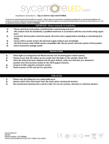
2.2 Installation procedure.
1. Before installation, make sure that the voltage in the 230V power-supply circuit is cut off.
2. Mount the PSU in a selected location and connect the wires.
3. Connect the power cables (~230VAC) to L-N terminals of the PSU. Connect the ground wire to the terminal marked by
the earth symbol – “ ” on the plate. Use a three-core cable (with a yellow and green PE protection wire) to make the
connection. Lead the cables to the appropriate terminals of the connection board through the bushing.
The shock protection circuit shall be performed with a particular care, i.e. the yellow and green
wire coat of the power cable shall stick to one side of the terminal marked with the ‘ ’ earth
symbol in the PSU enclosure. Operation of the power supply without a properly made and fully
operational shock protection circuit is UNACCEPTABLE! It can result in device damage or an
electric shock.
4. Mount the recorder in a designated area of the housing.
5. Connect the power supply of the DVR (by default, the device is equipped with a cable terminated with the DC 2.1
/ 5.5 plug).
6. Connect the camera cables to the AUX1…AUX16 connectors of the LB8 modules.
7. Connect the power (~230V).
8. Check the PSU output voltage:
- the PSU voltage without load should amount to U=13,8V DC.
9. Connect the batteries in parallel:
- battery output (+): BAT+ cable / red,
- battery output (-): BAT – cable / GND / black.
10. Check the PSU operation indicator: green LED
(on the power supply module).
11. After installing and checking proper working, the enclosure can be closed.
*
See chart 1

www.pulsar.pl PSUPS20A12CR
9
RED LED:
on – The PSU supplied with 230V AC voltage
off – no 230V AC mains supply
GREEN LED:
on – DC voltage at the AUX output
off - no DC voltage at the AUX output
3. Operating status indication.
The PSU is equipped with two diodes on the front panel:
4. Operation and use.
4.1 Overload or short circuit of the PSU output (SCP activation).
In case of overload, the output voltage is automatically shut off, and so is the LED indicator. The restoration of
the voltage takes place immediately once the failure (overload) is over.
4.2 Overload or short circuit of the recorder’s module or CCTV camera module
The modules of the recorder and CCTV cameras are protected against a short circuit by fuses (fuse-elements). In
case of fuse replacement, use a replacement of the same parameters, in conformity with specific norms and power
balance.
4.3 Battery-assisted operation.
The power supply is equipped with deep discharge battery protection (UVP). If the voltage at the battery terminals
drops below 9,5V during battery-assisted operation, the batteries will be disconnected.
4.4 Parallel connection of batteries.
The power supply has space for two parallel connected batteries. With this connection, the following rules should
be observed:
- Connect only new batteries: of the same manufacturer, type and the same capacity
- To minimize the rapid flow of current between the batteries, the batteries should be fully charged before connecting
with external charger.
- In the case of low battery, replace always both batteries at the same time.
4.5 Maintenance.
Any and all maintenance operations may be performed following the disconnection of the PSU from the power
supply network. The PSU does not require performing any specific maintenance measures. However, in case of dust,
clean the interior with compressed air. In case of fuse replacement, use a replacement of the same parameters.

www.pulsar.pl PSUPS20A12CR
10
WEEE MARK
According to the EU WEE Directive – It is required not to dispose of electric or electronic waste as
unsorted municipal waste and to collect such WEEE separatel.
CAUTION! The power supply unit is adapted for cooperation with the sealed lead-acid batteries (SLA). After the operation
period they must not be thrown but recycled according to the applicable law
Pulsar
Siedlec 150, 32-744 Łapczyca, Polska
Tel. (+48) 14-610-19-40, Fax. (+48) 14-610-19-50
http:// www.pulsar.pl, www.zasilacze.pl
/