Page is loading ...

YARWAY MODEL 11 CONTROL VALVES - SINGLE STAGE
INSTALLATION AND MAINTENANCE INSTRUCTIONS
UNPACKING
The Yarway water control valves are packed
with the greatest care in wooden boxes or
cartons for protection during handling or transit
to site.
After hydrostatic testing, the water control
valve is flushed through with a high grade of
preservative to protect machined and internal
surfaces from corrosion. If it is found, however,
that damage has occurred during shipment,
then this should be reported immediately to
your forwarder or Yarway representative.
Particular care should be taken when removing
the water control valve from its packing and
your special attention is required to check
that no damage has occurred to flange faces,
threading and butt weld profiles (see figure 1).
INSTALLATION OF A BUTT WELD WATER
CONTROL VALVE
Before installation, check the water control
valve for any visible damage. Make sure that
protective covers are removed and that butt
weld ends are cleaned. Verify with a handheld
flash light that the inlet and outlet connections
are free of any obstructions.
WELDING
The body material is indicated on the water
control valve. Follow an acceptable welding
code such as ASME IX or EN or your local
regulation for welding of the water control
valve. Make sure that the weld is clean, TIG
welding is preferable. The water control valve
should not be disassembled before welding.
INSTALLATION OF A FLANGED WATER
CONTROL VALVE
When the water control valve is fitted with
flanges make sure flanges are clean and that
suitable gaskets are available.
Do not re-use gaskets. In case of doubt,
consultyour local gasket supplier.
The water control valve is designed for clean
and filtered water otherwise a strainer is highly
recommended by Yarway.
Check for the ‘arrow flow direction indicator’ on
the body. Install the water control valve in such
a way that the flow direction is with the arrow.
Make sure that there is sufficient space to
remove the bonnet and actuator for cleaning
and inspection of the water control valve seat.
The water control valve is designed for clean
and filtered water otherwise a strainer is highly
recommended by Yarway.
Before installation these instructions must be fully read and understood
© 2017 Emerson. All Rights Reserved.Emerson.com/FinalControl VCIOM-03238-EN 18/06

2
STORAGE PROCEDURE
Upon receipt, check both the water control
valve and the packing case for any transit
damage. Any damage to the water control valve
should be rectified to prevent the ingress of
dust or water, prior to placing the water control
valve into storage.
Check the information contained on the
identification plate/tag plate anddocumentation
and return the water control valve to its packing
withprotective covers in place.
For short term storage, up to 6 months
duration, no additional preservation measures
are necessary. Retain the water control valve
in its original packing in a clean, dry indoor
location. If outdoor storage is unavoidable,
then the packing case should be enclosed in
awaterproofcover.
For long term storage use only a dry indoor
location. Apply a cosmoline type grease to
machined faces. Retain the water control valve
in its original packing and inspect at 3 monthly
intervals to ensure that no deterioration has
occurred.
Before placing the water control valve into
service, inspect all components, seals etc.,
to ensure correct functioning. Follow the
procedure for installation as described before.
YARWAY MODEL 11 CONTROL VALVES - SINGLE STAGE
INSTALLATION AND MAINTENANCE INSTRUCTIONS
MAINTENANCE
The water control valve requires little
maintenance. Make sure that pressure has
been relieved before opening the bonnet.
After removing the tag weld between the
body and seat, use the special tool (figure 2)
or another suitable tool to remove the seat.
The threading is standard right handed (counter
clockwise tounscrew).
Clean the water control valve parts by using
compressed air. As should always be the case,
use safety gloves, eye protection and other
safety equipment during your work.
Clean the gasket facing on both the body, seat
and bonnet. After cleaning, replace the gaskets
with new ones suitable for the pressure and
temperature. In case of doubt consult Yarway.
To assemble the seat use the special assembly
tool in combination with a torque wrench.
Keep pressure down on the torque wrench
when tightening the seat. The tightening torque
for the seat is approx 40 Nm. After assembly,
tag weld the seat to the body. Place bonnet on
the body and tighten the bolts with a torque
wrenchto 30 Nm.
Information for the welder: see WPS number
4N-4178-114.
PACKING SET
1. Completely remove old packing. Make sure
that surfaces contacting packing are clean.
Inspect the stuffing box and stem for
straightness, wear, scratches, pitting and
other abnormalities which would prevent
establishment of a good seal around the
packing. A smooth undamaged surface is
essential a good sealing. Repair or replace
as necessary.
2. Check packing rings for proper fit.
They should be push fit into stuffing box.
3. Install one ring at a time, in the proper
sequence, using a packing driver or gland
bushing. Facing must be seated individually
with a packing driver. Pre-compression
of each ring during installation is very
important for the tightness of the seal.
Do not use screwdriver or other sharp
object to seal the packing. This could
damage the packing and/or stem. If a
packing driver is used, make sure that the
diametrical clearances between the I.D. of
the driver and O.D. of the stem and the O.D.
of the driver and I.D. of the stuffing box do
not exceed 0.5mm (0.020").
4. Stagger the joints (if present) on each
successive ring 180° apart.
5. D
o not over compress the packing.
The amount of compression should be only
that which is required to the install the
correct number of rings into the stuffing box.
Compression of the packing in a partially
filled stuffing box, to make room for the rest
of the packing, can be accomplished using
the spacer and turning the packing gland.
6. When all the packing has been installed in
the stuffing box and the spacer and packing
gland are in place, adjust the compression
setting by turning the gland with a wrench
to seat and form the complete packing set
to the stuffing box and stem. Compress the
packing set enough to cause the packing
slightly grip the stem (if stem movement
is performed by hand, the stem should not
move). If the stem moves with stick slip,
the packing set is over tightened.
7. Secure the gland with the securing bolt in
one of the threaded holes.
8. Re-tightening of the gland is necessary
within a hour after start-up. During
operation it may be necessary to adjust the
gland. Check regularly.

3
•
•
19
•
1
•
13
•
14
•
•
•
5
7
4
•
3
18
•
9
12
•
•
6
•
2
•
20
11
•
10
NOTES
• Recommended spares
* May vary due to customer requirements
Materials and data of units supplied, may deviated from this Instruction Manual.
Please consult order documents in case of doubt.
The water control valve is classified under European directive 97/23 EC under
article 3, paragraph 3 (SEP).
Bench settings for the actuator:
Open: min.: 3.0 bar
Stroke 20 mm: min.: 4.3 bar
max.: 6.0 bar
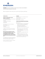
FIGURE 1 FIGURE 2 - SPECIAL TOOL FOR DISASSEMBLY
TABLE 1 - STANDARD MATERIALS
Item Name Material ASME Material EN
1 Body A105 P250GH
2• Seat AISI 431 EN 1.4057
3• Seal ring AISI 316L EN 1.4404
4• Packing Graphite/SS Graphite/SS
5 Bonnet A105 P250GH
6• Stem AISI 431 EN 1.4057
7• Packing set Graphite Graphite
9• Packing gland C. steel C. steel
10• Spacer AISI 431 EN 1.4057
11 Yoke plate C. steel C. steel
12 Bolt AISI 316 8.8
13 Actuator* C. steel C. steel
14 Coupling A351 gr. CF8 EN 1.4308
18• Securing bolt AISI 316 A4
19 Washer AISI 316 Steel
20 Lock nut C. steel C. steel
YARWAY MODEL 11 CONTROL VALVES - SINGLE STAGE
INSTALLATION AND MAINTENANCE INSTRUCTIONS
Neither Emerson, Emerson Automation Solutions, nor any of their affiliated entities assumes responsibility for the selection, use or maintenance of any product.
Responsibility for proper selection, use, and maintenance of any product remains solely with the purchaser and end user.
Yarway is a mark owned by one of the companies in the Emerson Automation Solutions business unit of Emerson Electric Co. Emerson Automation Solutions, Emerson
and the Emerson logo are trademarks and service marks of Emerson Electric Co. All other marks are the property of their respective owners.
The contents of this publication are presented for informational purposes only, and while every effort has been made to ensure their accuracy, they are not to be construed
as warranties or guarantees, express or implied, regarding the products or services described herein or their use or applicability. All sales are governed by our terms and
conditions, which are available upon request. We reserve the right to modify or improve the designs or specifications of such products at any time without notice.
Emerson.com/FinalControl
/