Page is loading ...

Owner’s Manual
© 2006 MILLER Electric Mfg. Co.
2006−06 FORM: OM-220 093B
Use above FORM number when ordering extra manuals.
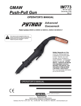
Push-Pull Adapter 195 324 For Millermatic
®
251
Models Eff w/LE152159
The push-pull adapter enables the Millermatic 251 to be used for aluminum MIG
welding by providing connections for the XR-A Edge gun, XR-A Pistol gun, or
XR-A Python gun.
The push−pull system for aluminum requires installation of U-groove drive rolls in
the Millermatic 251, as well as the correct contact tube, and drive rolls in the
welding gun. These parts are available in the drive roll and accessory kit (order
separately).
NOTE
1. Safety Symbol Definitions
Warning! Watch Out! There are possible hazards as
shown in the adjoining symbols.
Have only trained and qualified persons install, operate,
or service this unit. Call your distributor if you do not un-
derstand the directions. For WELDING SAFETY and
EMF information, read welding power source Owner’s
Manual.
Beware of electric shock from wiring. Turn Off welding
power source and disconnect power before installing this
kit. Reinstall all panels and covers.
Hot parts can cause burns. Welding makes parts very hot
− let them cool before touching.
Wear safety glasses with side shields. Cylinders contain gas under high pressure and can ex-
plode if damaged. Never let a welding electrode touch
any cylinder. Always secure cylinder to running gear, wall,
or other stationary support.
Drive rolls can injure − keep away from pinch points and
moving parts on wire feeder.
Welding wire can cause puncture wounds. Do not point
gun toward any part of the body or at other people when
threading welding wire, or anytime when running out wire
and not welding.
2. Specifications
Specification
Input Power 24 Volts AC (Provided By Millermatic 251 )
Control Circuit Voltage Provided to Gun 24 Volts DC
Welding Power Source Type Millermatic 251 Eff w/LE152159
Gun Requirement XR-A Edge Gun, XR-A Pistol Gun, or XR-A Python gun.
Wire Size And Type .035, .040, and .047 in. Aluminum
Connections Gun Power And Trigger Controls, Negative Weld Cable
Welding Process DC Gas Metal Arc Welding (GMAW)
Overall Dimensions Of Control Box
(Length x Width x Depth)
9 x 3 x 11 in (227 x 76 x 279 mm)
Weight 7 lb (3.2 kg)
3. Tools Needed

OM-220 093 Page 2
4. Preparing Millermatic 251 And Gun For Push-Pull Adapter Kit Installation
Make the changes listed in Sections A and B below prior to installing the push-pull
adapter.
NOTE
A. Changing Millermatic 251 Drive Roll
1 Drive Roll
Install U-groove drive rolls in the
Millermatic 251 to match wire
diameter. Drive rolls are included in
drive roll and accessory kit.
2 Drive Roll Securing Nut
Turn nut one click to secure drive
roll.
Ref. 802 990 / Ref. 802 064-D / Ref. 800 412-A
2
1
1
2
Top View
B. Changing XR-A Gun Drive Rolls
1 Barrel Assembly
2 Nut
3 Capscrew
XR-A Edge Gun: Loosen nut and
remove gun barrel assembly.
XR-A Pistol: Remove two
capscrews beneath cover to
remove barrel.
Install correct drive rolls in gun to
match wire diameter (see gun
Owner’s Manual). Drive rolls and
other required parts are included in
drive roll and accessory kit.
801 556-B / 151 599
1
XR-A Edge Gun
XR-A Pistol
1
2
3

OM-220 093 Page 3
5. Mounting Push-Pull Adapter
803 462
Y Turn Off and disconnect input
power.
1 Millermatic 251
2 Push-Pull Adapter
3 Screw
Remove two wrapper mounting screws
on lower right side of Millermatic 251 as
shown. Align adapter slots with mounting
holes and reinstall screws.
2
3
1
Notes
Work like a Pro!
Pros weld and cut
safely. Read the
safety rules at
the beginning
of this manual.

OM-220 093 Page 4
6. Connecting Push-Pull Adapter
803 432
.An XR-A Edge gun is shown in these
instructions.
Make connections as shown:
1 Millermatic 251
Install U-groove drive rolls in Millermatic 251
to match wire diameter. See Section 4 for
U-groove drive roll installation information.
Drive rolls are included in drive roll and
accessory kit.
2 XR-A Edge Gun
.See gun Owner’s Manual for information
on installing gun components.
Install correct liner and drive rolls in gun to
match wire diameter (see Section 4). Drive
rolls, liner, and other required parts are
included in drive roll and accessory kit.
See Section 8 for gun installation
instructions.
3 Gun Cable w/10-Pin Male Connector
4 Adapter Cable w/10-Pin Female
Connector
5 Adapter Cable w/10-Pin Male
Connector
6 Adapter Cable w/4-Pin Male
Connector
7 Adapter Negative (−) Weld Cable
Connect cable as shown in Section 7.
8 Work Cable w/Clamp
9 Adapter Negative (−) Weld Terminal
10 Gas Cylinder
Y Do not use gas pressure above 50
psi (345 kPa).
1
2
3
4
6
7
8
9
10
Connect gun and weld
cable as shown in
Sections 7 and 8.
5

OM-220 093 Page 5
7. Installing Adapter Work Cable
Ref. 802 474-E
3
2
1
1 Adapter Work Cable
2 Boot
Route cable through front panel
opening. Slide boot onto work
cable.
3 Negative (−) Output Terminal
Connect cable to terminal and
cover connection with boot.
From Adapter
8. Installing Welding Gun
1 Drive Roll Assembly
2 Pressure Arm Assembly
Open drive roll and pressure arm
assemblies.
3 Gun Liner
4 Wire Outlet Guide
.For welding guns prior to Serial No.
LE273538, wire outlet guide 202 216,
included with drive roll kits, must be
installed in gun.
Trim excess liner from end of gun so no
more than 3/32 in (2.4 mm) of liner extends
past wire outlet guide.
5 Gun Securing Knob
Loosen securing knob. Insert gun end
through opening until it bottoms
against drive assembly (make sure gun
end does not touch drive rolls). Tighten
knob.
6 Gun Trigger Plug
Connect plug to adapter cable w/10-pin
female connector (see Section 6).
Close the drive roll assembly. Leave
pressure arm assembly open.
Go to Step 9.
803 463
43
12
5
6
7
3/32 in
(2.4 mm) .Be sure to
trim liner
to proper
extension.

OM-220 093 Page 6
9. Installing 12 Inch Wire Spool And Adjusting Hub Tension
Use compression spring
with 8 in (200 mm) spools.
072 573-B / 802 922
Loosen spool tension nut so threaded shaft
is recessed 1/8 in (3 mm) inside of nut.
1/8 in (3 mm)
1 12 in (305 mm) Spool
2 Tension Nut
3 Shaft
Loosen spool tension nut so
threaded shaft is recessed 1/8 in
(3 mm) inside of nut.
1
2 3
2

OM-220 093 Page 7
10. Threading Welding Wire Through Millermatic 251
1 Wire Spool
2 Welding Wire
3 Inlet Wire Guide
4 Pressure Adjustment Knob
5 Drive Roll
6 Outlet Wire Guide
7 Gun Conduit Cable
Lay gun cable out straight.
4
7
35
621
6 in
(150 mm)
.Hold wire tightly to keep it
from unraveling.
Open pressure assembly. Pull and hold wire; cut off end.
Push wire thru guides into gun;
continue to hold wire.
Close and tighten pressure
assembly, and let go of wire.
803 463 / S-0627-A
Tighten
1
2
3
4
.Set pressure indicator to
1 for aluminum wire.
Pressure
Indicator
Scale
Set Adapter Run-In speed to 40%.
Thread wire through gun
(see Section 11).

OM-220 093 Page 8
11. Threading Welding Wire Through XR-A Gun
Ref. 802 193-A / 801 556
Tools Needed:
Y Welding wire is electrically live
when gun trigger is used to jog
wire.
.Refer to Section 10 for instructions on
feeding wire through Millermatic 251.
1 Pressure Roll Assembly
Lay gun cable out straight.
Open top cover, and open pressure roll as-
sembly. If not already done, remove gun
barrel assembly.
Press gun trigger until about 4 in (102 mm)
of wire is sticking out front of gun. Insert
wire into barrel liner and tighten barrel as-
sembly. Install correct size contact tube
and install collet nut.
Close top cover on gun. Press trigger
switch until about 6 in (152 mm) of wire is
sticking out end of contact tip. See final
pressure adjustment at bottom of page.
Feed wire to check drive roll
pressure. If necessary, slightly
tighten thumb nut inside gun.
.Do not exceed midrange setting.
Cut off wire. Close and latch wire
feeder door.
Y Turn Millermatic 251 Off.
Nonconductive
Surface
For XR-A Edge Gun:
.Procedure is the same for
pistol-grip gun.
For XR-A Pistol Gun:
For Both Guns:
1 Pressure Roll Assembly
2 Drive Roll
3 Thumbscrew
Lay gun cable out straight. Open top
cover, and lift pressure arm and open
pressure roll assembly. If not already
done, remove gun barrel assembly.
Manually thread wire along drive roll
groove. Close pressure roll assembly.
Press gun trigger until about 4 in (102 mm)
of wire is sticking out front of gun. Insert
wire into barrel liner and tighten barrel as-
sembly. Install correct size contact tube
and install collet nut. Reinstall gun cover.
4 Pressure Adjustment Knob
See final pressure adjustment at bottom of
page.
1
2
Turn On
Millermatic
251.
Turn On
Millermatic
251.
1
3
Remove barrel assembly before
threading wire through gun.
Remove barrel assembly
before threading wire
through gun.

OM-220 093 Page 9
12. Setting Push-Pull Adapter And XR-A Gun Controls
1 Adapter Run-In Speed Control
Use control to set run-in wire feed speed
before arc initiation.
After arc initiation, weld wire feed speed is
controlled by the wire speed setting on the
welding gun.
The scale around the run-in speed control
is a percent of weld wire feed speed.
If using .047 wire, set control to 10% for best
results. If using .040 wire, set control to 25%
for best results. If using .035 wire, set con-
trol to 40% for best results.
.The gun wire feed speed control adjusts
wire speed from minimum to maximum
setting as displayed on Millermatic 251.
2 Trigger
Press trigger to energize Millermatic 251,
weld output, start shielding gas flow, and
begin wire feed.
3 Wire Speed Control
Use control to adjust wire feed speed. The
numbers around the control are for
reference only.
1
2
3
2
3
803 432 / 151 666

OM-220 093 Page 10
13. Push-Pull Adapter Electrical Diagram
210 633-A

OM-220 093 Page 11
14. Parts
803 433
1
14
4
15
8
2
19
3
7
9
10
21
5
6
14
17
20
16
18
. Hardware is common and
not available unless listed.
22
23
Figure 15-1. Push-Pull Adapter
Description
Part
No.
Dia.
Mkgs.
Item
No.
Figure 15-1. Push-Pull Adapter
Quantity
1 211333 Case, Control Box 1. . . . . . . . . . . . . . . . . . . . . . . . . . . . . . . . . . . . . . . . . . . . . . . . . . . . . . . . . . . . . . . . .
2 211334 Baffle, Control Box 1. . . . . . . . . . . . . . . . . . . . . . . . . . . . . . . . . . . . . . . . . . . . . . . . . . . . . . . . . . . . . . . . .
3 211335 Cover, Control Box 1. . . . . . . . . . . . . . . . . . . . . . . . . . . . . . . . . . . . . . . . . . . . . . . . . . . . . . . . . . . . . . . . .
4 PLG5 211252 Cable, Interconnecting 2 Ft 7 In 1. . . . . . . . . . . . . . . . . . . . . . . . . . . . . . . . . . . . . . . . . . . . . . . .
5 PLG6 211253 Cable, Interconnecting 1 Ft 10 In 1. . . . . . . . . . . . . . . . . . . . . . . . . . . . . . . . . . . . . . . . . . . . . . .
6 PLG7 211257 Cable, Trigger 1 Ft 10 In 1. . . . . . . . . . . . . . . . . . . . . . . . . . . . . . . . . . . . . . . . . . . . . . . . . . . . . .
7 REED 211301 Switch, Reed 1. . . . . . . . . . . . . . . . . . . . . . . . . . . . . . . . . . . . . . . . . . . . . . . . . . . . . . . . . . . . . . .
8 PC1 216400 Circuit Card Assy, Motor Control 1. . . . . . . . . . . . . . . . . . . . . . . . . . . . . . . . . . . . . . . . . . . . . . .
9 WORK 097416 Terminal, Pwr Output Black 1. . . . . . . . . . . . . . . . . . . . . . . . . . . . . . . . . . . . . . . . . . . . . . . . .
10 180732 Boot, Negative Output Stud 1. . . . . . . . . . . . . . . . . . . . . . . . . . . . . . . . . . . . . . . . . . . . . . . . . . . . . . . . .
11 PLG3 131054 Conn, Rect Mini 045 2skt 2row Plug Cable Lkg (Not Shown) 1. . . . . . . . . . . . . . . . . . . . . . .
12 PLG1 115091 Conn, Rect Mini 045 10skt 2row Plug Cable Lkg (Not Shown) 1. . . . . . . . . . . . . . . . . . . . . .
13 PLG2 115092 Conn, Rect Mini 045 8skt 2row Plug Cable Lkg (Not Shown) 1. . . . . . . . . . . . . . . . . . . . . . .
14 139041 Bushing, Strain Relief .481/.617 Id X1.115 Mtg Hole 2. . . . . . . . . . . . . . . . . . . . . . . . . . . . . . . . . . . .
15 057358 Bushing, Snap−in Nyl 1.000 Id X 1.375 Mtg Hole 1. . . . . . . . . . . . . . . . . . . . . . . . . . . . . . . . . . . . . . .
16 134201 Stand−off Support, Pc Card .312/.375w/Post&lock .43 4. . . . . . . . . . . . . . . . . . . . . . . . . . . . . . . . . .
17 207076 Knob, Pointer .868 Dia. 1. . . . . . . . . . . . . . . . . . . . . . . . . . . . . . . . . . . . . . . . . . . . . . . . . . . . . . . . . . . . .
18 R1 208399 Pot, Cp Std Slot 1t 2. W 10k Linear W/Frict Tabs 1. . . . . . . . . . . . . . . . . . . . . . . . . . . . . . . . . . .
115093 Conn, Rect Mini 045 6skt 2row Plug Cable Lkg 1. . . . . . . . . . . . . . . . . . . . . . . . . . . . . . . . . . . . . . . . . . .
19 131515 Label, Warning Electric Shock And Arc Welding Can 1. . . . . . . . . . . . . . . . . . . . . . . . . . . . . . . . . . .
20 212154 Label, Dial Indicator Run−in 1. . . . . . . . . . . . . . . . . . . . . . . . . . . . . . . . . . . . . . . . . . . . . . . . . . . . . . . . .
21 180735 Washer, Output Stud 1. . . . . . . . . . . . . . . . . . . . . . . . . . . . . . . . . . . . . . . . . . . . . . . . . . . . . . . . . . . . . . .
22 600318 Cable, Weld Cop Strd No 3 Epdm Jkt 4 ft.. . . . . . . . . . . . . . . . . . . . . . . . . . . . . . . . . . . . . . . . . . . . . . . .
23 181169 Spacer, Output Stud 1. . . . . . . . . . . . . . . . . . . . . . . . . . . . . . . . . . . . . . . . . . . . . . . . . . . . . . . . . . . . . . . .

OM-220 093 Page 12
Notes
/