ESAB m3® Plasma Manual Gas Control Plasma System User manual
- Category
- Welding System
- Type
- User manual
This manual is also suitable for

Manual Gas Control Plasma System
Instruction Manual
0558009614 05/2011
This documentation is for ESAB equipment:
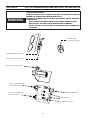
PCC-14 Plumbing Box part number 0558005840
Plasma Control Interface part number 0560948696 (serial #’s AA-K004001,002,003,004,005)
PCC-14 Plumbing Box
Plasma Control Interface

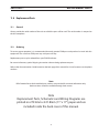
This equipment will perform in conformity with the description thereof contained in this manual and accompa-
nying labels and/or inserts when installed, operated, maintained and repaired in accordance with the instruc-
tions provided. This equipment must be checked periodically. Malfunctioning or poorly maintained equipment
should not be used. Parts that are broken, missing, worn, distorted or contaminated should be replaced imme-
diately. Should such repair or replacement become necessary, the manufacturer recommends that a telephone
or written request for service advice be made to the Authorized Distributor from whom it was purchased.
This equipment or any of its parts should not be altered without the prior written approval of the manufacturer.
The user of this equipment shall have the sole responsibility for any malfunction which results from improper
use, faulty maintenance, damage, improper repair or alteration by anyone other than the manufacturer or a ser-
vice facility designated by the manufacturer.
BE SURE THIS INFORMATION REACHES THE OPERATOR.
YOU CAN GET EXTRA COPIES THROUGH YOUR SUPPLIER.
These INSTRUCTIONS are for experienced operators. If you are not fully familiar with the
principles of operation and safe practices for arc welding and cutting equipment, we urge
you to read our booklet, “Precautions and Safe Practices for Arc Welding, Cutting, and
Gouging,” Form 52-529. Do NOT permit untrained persons to install, operate, or maintain
this equipment. Do NOT attempt to install or operate this equipment until you have read
and fully understand these instructions. If you do not fully understand these instructions,
contact your supplier for further information. Be sure to read the Safety Precautions be-
fore installing or operating this equipment.
CAUTION
USER RESPONSIBILITY
READ AND UNDERSTAND THE INSTRUCTION MANUAL BEFORE INSTALLING OR OPERATING.
PROTECT YOURSELF AND OTHERS!

TABLE OF CONTENTS
Section / Title Page
1.0 Safety Precautions. . . . . . . . . . . . . . . . . . . . . . . . . . . . . . . . . . . . . . . . . . . . . . . . . . . . . . . . . . . . . . . . . . . . . . . . . . . . . . . . . . . . . . . . . . . . . . . . . . . . . . . . . . . 5
1.1 Safety - English . . . . . . . . . . . . . . . . . . . . . . . . . . . . . . . . . . . . . . . . . . . . . . . . . . . . . . . . . . . . . . . . . . . . . . . . . . . . . . . . . . . . . . . . . . . . . . . . . . . . . . 5
1.2 Safety - Spanish. . . . . . . . . . . . . . . . . . . . . . . . . . . . . . . . . . . . . . . . . . . . . . . . . . . . . . . . . . . . . . . . . . . . . . . . . . . . . . . . . . . . . . . . . . . . . . . . . . . . . . 9
1.3 Safety - French . . . . . . . . . . . . . . . . . . . . . . . . . . . . . . . . . . . . . . . . . . . . . . . . . . . . . . . . . . . . . . . . . . . . . . . . . . . . . . . . . . . . . . . . . . . . . . . . . . . . . . 13
2.0 ESAB m3 Manual Gas Control System. . . . . . . . . . . . . . . . . . . . . . . . . . . . . . . . . . . . . . . . . . . . . . . . . . . . . . . . . . . . . . . . . . . . . . . . . . . . . . . . . . . . . . . . 17
PCC-14 Plumbing Box. . . . . . . . . . . . . . . . . . . . . . . . . . . . . . . . . . . . . . . . . . . . . . . . . . . . . . . . . . . . . . . . . . . . . . . . . . . . . . . . . . . . . . . . . . . . . . . . . . . . . . . . . . . . . . 19
3.0 General . . . . . . . . . . . . . . . . . . . . . . . . . . . . . . . . . . . . . . . . . . . . . . . . . . . . . . . . . . . . . . . . . . . . . . . . . . . . . . . . . . . . . . . . . . . . . . . . . . . . . . . . . . . . . . . . . . . . . . 21
3.1 Scope. . . . . . . . . . . . . . . . . . . . . . . . . . . . . . . . . . . . . . . . . . . . . . . . . . . . . . . . . . . . . . . . . . . . . . . . . . . . . . . . . . . . . . . . . . . . . . . . . . . . . . . . . . . . . . .21
3.2 Plumbing Box Spark Gap Adjustment. . . . . . . . . . . . . . . . . . . . . . . . . . . . . . . . . . . . . . . . . . . . . . . . . . . . . . . . . . . . . . . . . . . . . . . . . . . . . . . .24
3.3 Plumbing Box Connections. . . . . . . . . . . . . . . . . . . . . . . . . . . . . . . . . . . . . . . . . . . . . . . . . . . . . . . . . . . . . . . . . . . . . . . . . . . . . . . . . . . . . . . . . .25
3.4 EPP-201 / EPP-360 Torch Connections to Plumbing Box. . . . . . . . . . . . . . . . . . . . . . . . . . . . . . . . . . . . . . . . . . . . . . . . . . . . . . . . . . . . . . .27
3.5 PCC-14 Plumbing Box Mounting Hole Locations. . . . . . . . . . . . . . . . . . . . . . . . . . . . . . . . . . . . . . . . . . . . . . . . . . . . . . . . . . . . . . . . . . . . . .29
Plasma Control Interface. . . . . . . . . . . . . . . . . . . . . . . . . . . . . . . . . . . . . . . . . . . . . . . . . . . . . . . . . . . . . . . . . . . . . . . . . . . . . . . . . . . . . . . . . . . . . . . . . . . . . . . . . . . 31
3.6 General . . . . . . . . . . . . . . . . . . . . . . . . . . . . . . . . . . . . . . . . . . . . . . . . . . . . . . . . . . . . . . . . . . . . . . . . . . . . . . . . . . . . . . . . . . . . . . . . . . . . . . . . . . . . . . . . . . .33
3.7 Scope. . . . . . . . . . . . . . . . . . . . . . . . . . . . . . . . . . . . . . . . . . . . . . . . . . . . . . . . . . . . . . . . . . . . . . . . . . . . . . . . . . . . . . . . . . . . . . . . . . . . . . . . . . . . . . .33
3.8 Plasma Control Interface Connections . . . . . . . . . . . . . . . . . . . . . . . . . . . . . . . . . . . . . . . . . . . . . . . . . . . . . . . . . . . . . . . . . . . . . . . . . . . . . . .34
3.9 Typical / Recommended E-stop Connection . . . . . . . . . . . . . . . . . . . . . . . . . . . . . . . . . . . . . . . . . . . . . . . . . . . . . . . . . . . . . . . . . . . . . . . . .37
3.10 Control Sequence . . . . . . . . . . . . . . . . . . . . . . . . . . . . . . . . . . . . . . . . . . . . . . . . . . . . . . . . . . . . . . . . . . . . . . . . . . . . . . . . . . . . . . . . . . . . . . . . . . .38
3.11 Plasma Control Interface Mounting Hole Locations . . . . . . . . . . . . . . . . . . . . . . . . . . . . . . . . . . . . . . . . . . . . . . . . . . . . . . . . . . . . . . . . . .39
3.12 Plasma Control Interface STATUS Codes. . . . . . . . . . . . . . . . . . . . . . . . . . . . . . . . . . . . . . . . . . . . . . . . . . . . . . . . . . . . . . . . . . . . . . . . . . . . . .40
4.0 Maintenance . . . . . . . . . . . . . . . . . . . . . . . . . . . . . . . . . . . . . . . . . . . . . . . . . . . . . . . . . . . . . . . . . . . . . . . . . . . . . . . . . . . . . . . . . . . . . . . . . . . . . . . . . . . . . . . 41
4.1 General . . . . . . . . . . . . . . . . . . . . . . . . . . . . . . . . . . . . . . . . . . . . . . . . . . . . . . . . . . . . . . . . . . . . . . . . . . . . . . . . . . . . . . . . . . . . . . . . . . . . . . . . . . . . . 41
4.2 Cleaning . . . . . . . . . . . . . . . . . . . . . . . . . . . . . . . . . . . . . . . . . . . . . . . . . . . . . . . . . . . . . . . . . . . . . . . . . . . . . . . . . . . . . . . . . . . . . . . . . . . . . . . . . . . . 41
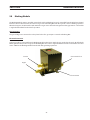
5.0 Marking Module . . . . . . . . . . . . . . . . . . . . . . . . . . . . . . . . . . . . . . . . . . . . . . . . . . . . . . . . . . . . . . . . . . . . . . . . . . . . . . . . . . . . . . . . . . . . . . . . . . . . . . . . . . . .43
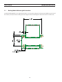
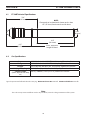
5.1 Marking Module Mounting Hole Locations . . . . . . . . . . . . . . . . . . . . . . . . . . . . . . . . . . . . . . . . . . . . . . . . . . . . . . . . . . . . . . . . . . . . . . . . . .44
6.0 PT-36R Plasma Torch . . . . . . . . . . . . . . . . . . . . . . . . . . . . . . . . . . . . . . . . . . . . . . . . . . . . . . . . . . . . . . . . . . . . . . . . . . . . . . . . . . . . . . . . . . . . . . . . . . . . . . . .45
6.1 PT-36R Technical Specications. . . . . . . . . . . . . . . . . . . . . . . . . . . . . . . . . . . . . . . . . . . . . . . . . . . . . . . . . . . . . . . . . . . . . . . . . . . . . . . . . . . . . .46
6.2 Gas Specications. . . . . . . . . . . . . . . . . . . . . . . . . . . . . . . . . . . . . . . . . . . . . . . . . . . . . . . . . . . . . . . . . . . . . . . . . . . . . . . . . . . . . . . . . . . . . . . . . . .46
6.3 Recommended Regulators . . . . . . . . . . . . . . . . . . . . . . . . . . . . . . . . . . . . . . . . . . . . . . . . . . . . . . . . . . . . . . . . . . . . . . . . . . . . . . . . . . . . . . . . . .47
6.4 PT-36R Torch Technical Specications. . . . . . . . . . . . . . . . . . . . . . . . . . . . . . . . . . . . . . . . . . . . . . . . . . . . . . . . . . . . . . . . . . . . . . . . . . . . . . . . 47
7.0 Coolant Circulator . . . . . . . . . . . . . . . . . . . . . . . . . . . . . . . . . . . . . . . . . . . . . . . . . . . . . . . . . . . . . . . . . . . . . . . . . . . . . . . . . . . . . . . . . . . . . . . . . . . . . . . . . .49
7.1 Specications . . . . . . . . . . . . . . . . . . . . . . . . . . . . . . . . . . . . . . . . . . . . . . . . . . . . . . . . . . . . . . . . . . . . . . . . . . . . . . . . . . . . . . . . . . . . . . . . . . . . . . .50
7.2 Installation. . . . . . . . . . . . . . . . . . . . . . . . . . . . . . . . . . . . . . . . . . . . . . . . . . . . . . . . . . . . . . . . . . . . . . . . . . . . . . . . . . . . . . . . . . . . . . . . . . . . . . . . . . 51
7.3 Input Power Connections . . . . . . . . . . . . . . . . . . . . . . . . . . . . . . . . . . . . . . . . . . . . . . . . . . . . . . . . . . . . . . . . . . . . . . . . . . . . . . . . . . . . . . . . . . .52
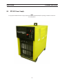
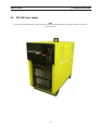
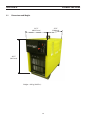
8.0 EPP-201 Power Supply . . . . . . . . . . . . . . . . . . . . . . . . . . . . . . . . . . . . . . . . . . . . . . . . . . . . . . . . . . . . . . . . . . . . . . . . . . . . . . . . . . . . . . . . . . . . . . . . . . . . . .55
8.1 Dimensions and Weight. . . . . . . . . . . . . . . . . . . . . . . . . . . . . . . . . . . . . . . . . . . . . . . . . . . . . . . . . . . . . . . . . . . . . . . . . . . . . . . . . . . . . . . . . . . . .56
8.2 Input Power Connection . . . . . . . . . . . . . . . . . . . . . . . . . . . . . . . . . . . . . . . . . . . . . . . . . . . . . . . . . . . . . . . . . . . . . . . . . . . . . . . . . . . . . . . . . . . .57
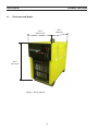
9.0 EPP-360 Power Supply . . . . . . . . . . . . . . . . . . . . . . . . . . . . . . . . . . . . . . . . . . . . . . . . . . . . . . . . . . . . . . . . . . . . . . . . . . . . . . . . . . . . . . . . . . . . . . . . . . . . . .59
9.1 Dimensions and Weight . . . . . . . . . . . . . . . . . . . . . . . . . . . . . . . . . . . . . . . . . . . . . . . . . . . . . . . . . . . . . . . . . . . . . . . . . . . . . . . . . . . . . . . . . . . . .60
9.2 Input Power Connection . . . . . . . . . . . . . . . . . . . . . . . . . . . . . . . . . . . . . . . . . . . . . . . . . . . . . . . . . . . . . . . . . . . . . . . . . . . . . . . . . . . . . . . . . . . . 61

4
TABLE OF CONTENTS
10.0 HOSES AND CABLES . . . . . . . . . . . . . . . . . . . . . . . . . . . . . . . . . . . . . . . . . . . . . . . . . . . . . . . . . . . . . . . . . . . . . . . . . . . . . . . . . . . . . . . . . . . . . . . . . . . . . . . .63
10.1 Hoses. . . . . . . . . . . . . . . . . . . . . . . . . . . . . . . . . . . . . . . . . . . . . . . . . . . . . . . . . . . . . . . . . . . . . . . . . . . . . . . . . . . . . . . . . . . . . . . . . . . . . . . . . . . . . . .63
10.2 Cables. . . . . . . . . . . . . . . . . . . . . . . . . . . . . . . . . . . . . . . . . . . . . . . . . . . . . . . . . . . . . . . . . . . . . . . . . . . . . . . . . . . . . . . . . . . . . . . . . . . . . . . . . . . . . . . . .68
11.0 Replacement Parts. . . . . . . . . . . . . . . . . . . . . . . . . . . . . . . . . . . . . . . . . . . . . . . . . . . . . . . . . . . . . . . . . . . . . . . . . . . . . . . . . . . . . . . . . . . . . . . . . . . . . . . . . .71
11.1 General . . . . . . . . . . . . . . . . . . . . . . . . . . . . . . . . . . . . . . . . . . . . . . . . . . . . . . . . . . . . . . . . . . . . . . . . . . . . . . . . . . . . . . . . . . . . . . . . . . . . . . . . . . . . .71
11.2 Ordering. . . . . . . . . . . . . . . . . . . . . . . . . . . . . . . . . . . . . . . . . . . . . . . . . . . . . . . . . . . . . . . . . . . . . . . . . . . . . . . . . . . . . . . . . . . . . . . . . . . . . . . . . . . .71
Diagrams and Parts List . . . . . . . . . . . . . . . . . . . . . . . . . . . . . . . . . . . . . . . . . . . . . . . . . . . . . . . . . . . . . . . . . . . . . . . . . . . . . . . . . . . . . . . attached packet

5
SECTION 1 SAFETY PRECAUTIONS
1.0 Safety Precautions
1.1 Safety - English
WARNING: These Safety Precautions are
for your protection. They summarize pre-
cautionary information from the references
listed in Additional Safety Information sec-
tion. Before performing any installation or operating
procedures, be sure to read and follow the safety precau-
tions listed below as well as all other manuals, material
safety data sheets, labels, etc. Failure to observe Safety
Precautions can result in injury or death.
PROTECT YOURSELF AND OTHERS --
Some welding, cutting, and gouging
processes are noisy and require ear
protection. The arc, like the sun, emits
ultraviolet (UV) and other radiation
and can injure skin and eyes. Hot metal can cause
burns. Training in the proper use of the processes
and equipment is essential to prevent accidents.
Therefore:
1. Always wear safety glasses with side shields in any
work area, even if welding helmets, face shields, and
goggles are also required.
2. Use a face shield tted with the correct lter and
cover plates to protect your eyes, face, neck, and
ears from sparks and rays of the arc when operating
or observing operations. Warn bystanders not to
watch the arc and not to expose themselves to the
rays of the electric-arc or hot metal.
3. Wear ameproof gauntlet type gloves, heavy long-
sleeve shirt, cuess trousers, high-topped shoes,
and a welding helmet or cap for hair protection, to
protect against arc rays and hot sparks or hot metal.
A ameproof apron may also be desirable as protec-
tion against radiated heat and sparks.
4. Hot sparks or metal can lodge in rolled up sleeves,
trouser cus, or pockets. Sleeves and collars should
be kept buttoned, and open pockets eliminated from
the front of clothing.
5. Protect other personnel from arc rays and hot
sparks with a suitable non-ammable partition or
curtains.
6. Use goggles over safety glasses when chipping slag
or grinding. Chipped slag may be hot and can y far.
Bystanders should also wear goggles over safety
glasses.
FIRES AND EXPLOSIONS -- Heat from
ames and arcs can start res. Hot
slag or sparks can also cause res and
explosions. Therefore:
1. Remove all combustible materials well away from
the work area or cover the materials with a protec-
tive non-ammable covering. Combustible materials
include wood, cloth, sawdust, liquid and gas fuels,
solvents, paints and coatings, paper, etc.
2. Hot sparks or hot metal can fall through cracks or
crevices in oors or wall openings and cause a hid-
den smoldering re or res on the oor below. Make
certain that such openings are protected from hot
sparks and metal.“
3. Do not weld, cut or perform other hot work until the
workpiece has been completely cleaned so that there
are no substances on the workpiece which might
produce ammable or toxic vapors. Do not do hot
work on closed containers. They may explode.
4. Have re extinguishing equipment handy for instant
use, such as a garden hose, water pail, sand bucket,
or portable re extinguisher. Be sure you are trained
in its use.
5. Do not use equipment beyond its ratings. For ex-
ample, overloaded welding cable can overheat and
create a re hazard.
6. After completing operations, inspect the work area
to make certain there are no hot sparks or hot metal
which could cause a later re. Use re watchers when
necessary.
7. For additional information, refer to NFPA Standard
51B, "Fire Prevention in Use of Cutting and Welding
Processes", available from the National Fire Protec-
tion Association, Batterymarch Park, Quincy, MA
02269.
ELECTRICAL SHOCK -- Contact with
live electrical parts and ground can
cause severe injury or death. DO NOT
use AC welding current in damp areas,
if movement is conned, or if there is
danger of falling.

6
SECTION 1 SAFETY PRECAUTIONS
1. Be sure the power source frame (chassis) is con-
nected to the ground system of the input power.
2. Connect the workpiece to a good electrical
ground.
3. Connect the work cable to the workpiece. A poor
or missing connection can expose you or others
to a fatal shock.
4. Use well-maintained equipment. Replace worn or
damaged cables.
5. Keep everything dry, including clothing, work
area, cables, torch/electrode holder, and power
source.
6. Make sure that all parts of your body are insulated
from work and from ground.
7. Do not stand directly on metal or the earth while
working in tight quarters or a damp area; stand
on dry boards or an insulating platform and wear
rubber-soled shoes.
8. Put on dry, hole-free gloves before turning on the
power.
9. Turn o the power before removing your gloves.
10. Refer to ANSI/ASC Standard Z49.1 (listed on
next page) for specic grounding recommenda-
tions. Do not mistake the work lead for a ground
cable.
ELECTRIC AND MAGNETIC FIELDS
— May be dangerous. Electric cur-
rent owing through any conduc-
tor causes localized Electric and
Magnetic Fields (EMF). Welding and
cutting current creates EMF around welding cables
and welding machines. Therefore:
1. Welders having pacemakers should consult their
physician before welding. EMF may interfere with
some pacemakers.
2. Exposure to EMF may have other health eects which
are unknown.
3. Welders should use the following procedures to
minimize exposure to EMF:
A. Route the electrode and work cables together.
Secure them with tape when possible.
B. Never coil the torch or work cable around your
body.
C. Do not place your body between the torch and
work cables. Route cables on the same side of
your body.
D. Connect the work cable to the workpiece as close
as possible to the area being welded.
E. Keep welding power source and cables as far
away from your body as possible.
FUMES AND GASES -- Fumes and
gases, can cause discomfort or harm,
particularly in conned spaces. Do
not breathe fumes and gases. Shield-
ing gases can cause asphyxiation.
Therefore:
1. Always provide adequate ventilation in the work area
by natural or mechanical means. Do not weld, cut, or
gouge on materials such as galvanized steel, stain-
less steel, copper, zinc, lead, beryllium, or cadmium
unless positive mechanical ventilation is provided.
Do not breathe fumes from these materials.
2. Do not operate near degreasing and spraying opera-
tions. The heat or arc rays can react with chlorinated
hydrocarbon vapors to form phosgene, a highly
toxic gas, and other irritant gases.
3. If you develop momentary eye, nose, or throat ir-
ritation while operating, this is an indication that
ventilation is not adequate. Stop work and take
necessary steps to improve ventilation in the work
area. Do not continue to operate if physical discom-
fort persists.
4. Refer to ANSI/ASC Standard Z49.1 (see listing below)
for specic ventilation recommendations.

7
SECTION 1 SAFETY PRECAUTIONS
5. WARNING: This product, when used for welding
or cutting, produces fumes or gases
which contain chemicals known to
the State of California to cause birth
defects and, in some cases, cancer.
(California Health & Safety Code
§25249.5 et seq.)
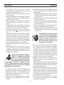
CYLINDER HANDLING -- Cylinders,
if mishandled, can rupture and vio-
lently release gas. Sudden rupture
of cylinder, valve, or relief device can
injure or kill. Therefore:
1. Use the proper gas for the process and use the
proper pressure reducing regulator designed to
operate from the compressed gas cylinder. Do not
use adaptors. Maintain hoses and ttings in good
condition. Follow manufacturer's operating instruc-
tions for mounting regulator to a compressed gas
cylinder.
2. Always secure cylinders in an upright position by
chain or strap to suitable hand trucks, undercar-
riages, benches, walls, post, or racks. Never secure
cylinders to work tables or xtures where they may
become part of an electrical circuit.
3. When not in use, keep cylinder valves closed. Have
valve protection cap in place if regulator is not con-
nected. Secure and move cylinders by using suitable
hand trucks. Avoid rough handling of cylinders.
4. Locate cylinders away from heat, sparks, and ames.
Never strike an arc on a cylinder.
5. For additional information, refer to CGA Standard P-1,
"Precautions for Safe Handling of Compressed Gases
in Cylinders", which is available from Compressed
Gas Association, 1235 Jeerson Davis Highway,
Arlington, VA 22202.
EQUIPMENT MAINTENANCE -- Faulty or
improperly maintained equipment can
cause injury or death. Therefore:
1. Always have qualied personnel perform the instal-
lation, troubleshooting, and maintenance work.
Do not perform any electrical work unless you are
qualied to perform such work.
2. Before performing any maintenance work inside a
power source, disconnect the power source from
the incoming electrical power.
3. Maintain cables, grounding wire, connections, power
cord, and power supply in safe working order. Do
not operate any equipment in faulty condition.
4. Do not abuse any equipment or accessories. Keep
equipment away from heat sources such as furnaces,
wet conditions such as water puddles, oil or grease,
corrosive atmospheres and inclement weather.
5. Keep all safety devices and cabinet covers in position
and in good repair.
6. Use equipment only for its intended purpose. Do
not modify it in any manner.
ADDITIONAL SAFETY INFORMATION -- For
more information on safe practices for
electric arc welding and cutting equip-
ment, ask your supplier for a copy of
"Precautions and Safe Practices for Arc
Welding, Cutting and Gouging", Form
52-529.
The following publications, which are available from
the American Welding Society, 550 N.W. LeJuene Road,
Miami, FL 33126, are recommended to you:
1. ANSI/ASC Z49.1 - "Safety in Welding and Cutting"
2. AWS C5.1 - "Recommended Practices for Plasma Arc
Welding"
3. AWS C5.2 - "Recommended Practices for Plasma Arc
Cutting"
4. AWS C5.3 - "Recommended Practices for Air Carbon
Arc Gouging and Cutting"

8
SECTION 1 SAFETY PRECAUTIONS
5. AWS C5.5 - "Recommended Practices for Gas Tung-
sten Arc Welding“
6. AWS C5.6 - "Recommended Practices for Gas Metal
Arc Welding"“
7. AWS SP - "Safe Practices" - Reprint, Welding Hand-
book.
8. ANSI/AWS F4.1, "Recommended Safe Practices for
Welding and Cutting of Containers That Have Held
Hazardous Substances."
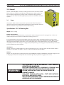
MEANING OF SYMBOLS - As used
throughout this manual: Means Atten-
tion! Be Alert! Your safety is involved.
Means immediate hazards which,
if not avoided, will result in im-
mediate, serious personal injury
or loss of life.
Means potential hazards which
could result in personal injury or
loss of life.
Means hazards which could result
in minor personal injury.
Page is loading ...
Page is loading ...
Page is loading ...
Page is loading ...
Page is loading ...
Page is loading ...
Page is loading ...
Page is loading ...

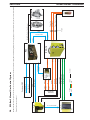
SECTION 2 INTERCONNECT DIAGRAM
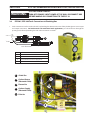
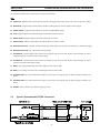
2.0 ESAB m3 Manual Gas Control System
The Manual Gas Control System consists of several components: Plasma Control Interface (PCI), PCC-14 Plumbing Box, Power Supply (PS), Coolant Circulator (CC), Torch and customer CNC.
Dotted line denotes optional
PCC-OUT
PCC-IN
PCC-PA
PCC-PWR
PS-PA
PS-IC
CC-IC
PS-PWR
PCC-SHG
PCC-STG
PCC-VDR
PCC-CTL
PCI-CTL
PCI-VDR
PCC-CG
CC-IN
CC-OUT
PS-ES
PS-CC
PCI-ES
PCI-EP
PCI-CI
PCI-CC
SM-AS
PCI-AS
PT-36R
POWER
DATA
LIQUID Optional
GAS
PCC-AR
REG-AR
REG-CG
REG-STG
REG-SHG
(optional)
(optional)
(optional)
Customer CNC
Ext. 115/230VAC
Control Interface
PS Contol Cable
E-Stop
ESAB m Manual Gas Control System
Ar
Cut Gas
Start Gas
Shield Gas
Power Cable
Pilot Arc Cable
Coolant Supply Hose
Coolant Return Hose
Argon Select
PCI
Mark / Cut
Switching
Module
PS
CC
PCC-14
Plasma Gas
Shield Gas
Power, Pilot Arc, Coolant
Air Curtain
Torch
Bubble Muffler
VDR
Bubble Muffler / Air Curtain Control
PCC-14 Control
CC-11 Control Cable
3
Regulated
Gas Supply
(optional)

18
SECTION 2 INTERCONNECT DIAGRAM
Page is loading ...
Page is loading ...

21
SECTION 3 PCC14 PLUMBING BOX DESCRIPTION / INSTALLATION
The PCC-14 Plumbing Box is a Plasmarc Cutting Control used to connect the PT-36R
Plasma Torch to a remotely located EPP-201 or EPP-360 power supply system. The
PCC-14 includes high frequency starting circuits to eliminate starting problems
with long torches and to minimize high frequency interference with other customer
systems.
WARNING
THIS EQUIPMENT CAN BE HAZARDOUS IF NOT PROPERLY
OPERATED AND MAINTAINED.
READ AND UNDERSTAND ALL EQUIPMENT LITERATURE AND
WARNING LABELS BEFORE OPERATING THIS EQUIPMENT.
FOLLOW THESE INSTRUCTIONS TO PREVENT INJURY OR
PROPERTY DAMAGE.
YOU MUST COMPLY WITH LOCAL, STATE AND NATIONAL
ELECTRICAL AND SAFETY CODES.
ONLY TRAINED PERSONNEL SHOULD PERFORM MAINTENANCE
OR REPAIRS ON THIS EQUIPMENT.
3.0 General
3.1 Scope
The purpose of this manual is to provide the operator with all the information re-
quired to install and operate the Plumbing Box & Plasma Control Interface. Technical
reference material is also provided to assist in troubleshooting.
Specications: PCC-14 Plumbing Box
Weight: 41lbs. (18.6 kg)
Plasma and Start Gases:
The PCC-14 may be used with O2, N2, Air, or Ar/H2 with a maximum input pressure of 110 psig (7.6 bar). ***These are
maximum input pressures and do not reect actual cutting pressures.***
It is recommended, but not required, that N2 be used as the start gas when using Ar/H2. The ow rate of gas will de-
pend on the pressure set, the torch connected to the plumbing box, and the parts installed in the torch. Without a torch
attached, the maximum ow rate for these gases at 100 psig (6.9 bar) is about 1000 scfh (28.3 cu-m/h). The minimum
acceptable pressure for the start gas is 19 psig (1.3 bar); for the plasma gas it is 24 psig (1.7 bar). Below these pressures the
pressure switches may not be satised.
Shield Gases:
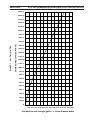
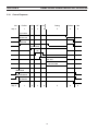
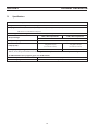
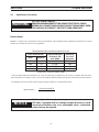
The PCC-14 may be used with Air, N2, Ar, or CO2. The maximum pressure is 110 psig (7.6 bar). This will result in a ow of
250 scfh (7.1 cu-m/h) N2. See Graph 3-1. There is no pressure interlock on the shield gas.
Coolant:
The PCC-14 is designed for use with plasma torch coolant (ESAB P/N’s 156F05 or 0558004297). Maximum design pressure
is 200 psig (13.8 bar). Flow rates depend on the torch but typically vary from 0.9 to 2 gpm (4.1 to 9.1 l/m).

22
SECTION 3 PCC14 PLUMBING BOX DESCRIPTION / INSTALLATION
Gas Purging:
When switching between Ar/H2 and an oxidizing gas (air or oxygen) it is recommended that the following procedure be
followed:
1. Turn o the gas.
2. Put the system into plasma gas test until line pressure is exhausted. If the start gas is being switched to or from Ar/
H2, switch to start gas test until that line is exhausted as well.
3. Disconnect the old gas and connect a relatively inert gas such as nitrogen, argon, carbon dioxide, C-25, etc. Set the
pressure to 50 psig (3.5 bar) and purge each aected line for 60 seconds.
4. Then shut o the gas and exhaust each line per Step 2.
5. Connect the gas to be used. Set the pressure to recommended values for the cutting condition to be used, and
purge each aected line for 15 seconds per 25 ft. (7.6 m) of line.
Flashback arrestors are required to prevent re from propagating
back to the gas supply through lines carrying oxygen or fuel gases.
Use AWG 2/0 power cable to carry electrode current from the power
source to the PCC-14. See section 9.0 for additional cables.
Avoid using the same supply lines for both oxygen and air if oil may
be mixed with the air. Oil in the presence of 100% oxygen can be
highly ammable.
Failure to observe above cautions may result in personal injury and /
or damage to the equipment.
CAUTION
Note:
The expected life of the internal exible hoses is 10 years. Replace them earlier if cracking or brittleness is noted.
Note:
When marking, ensure the start gas line is pressurized to avoid pressure switch errors.
Marking option
With the optional Marking Module installed, the PCC-14 will allow you to switch the cut gas to Argon for plate marking. With
the Marking Module installed, Argon gas input to the Marking Module is 125 psig (8.6 Bar).

23
SECTION 3 PCC14 PLUMBING BOX DESCRIPTION / INSTALLATION
250 (7.1)
240 (6.8)
230 (6.5)
220 (6.2)
210 (5.9)
200 (5.7)
190 (5.4)
180 (5.1)
170 (4.8)
160 (4.5)
150 (4.2)
140 (4.0)
130 (3.7)
120 (3.4)
110 (3.1)
100 (2.8)
90 (2.5)
80 (2.3)
70 (2.0)
60 (1.7)
50 (1.4)
40 (1.1)
30 (0.8)
20 (0.6)
10 (0.3)
0
0 10 20 30 40 50 60 70 80 90 100 110 120 130
(0.7) (1.4) (2.1) (2.8) (3.5) (4.1) (4.8) (5.5) (6.2) (6.9) (7.6) (8.3) (9.0)
PSIG (BAR) Pressure Setting to 0.052 in. (1.32 mm) Diameter Orice
Shield Gas Flow SCFH (CU-M/H) N
2
Graph 3-1 - Gas Pressure / Flow

24
SECTION 3 PCC14 PLUMBING BOX DESCRIPTION / INSTALLATION
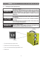
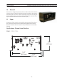
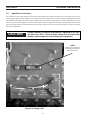
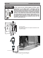
3.2 Plumbing Box Spark Gap Adjustment
1. Disconnect input power to power source.
2. Remove access cover from spark gap opening.
3. Check / set to recommended spark gap of 0.040” (1 mm).
4. Replace cover.
Spark Gap
Access Cover
Spark Gap
ELECTRICITY CAN KILL!
HIGH VOLTAGE CAN BE PRESENT BEHIND COVER PLATE. DO NOT OP
ERATE WITHOUT COVER PLATE IN PLACE. BEFORE REMOVING COVER
PLATE OR PERFORMING ANY MAINTENANCE OR ASSEMBLY OF THIS
EQUIPMENT, ENSURE THE POWER SOURCE IS TURNED OFF AND DIS
CONNECTED.
WARNING
Only qualied maintenance personnel should repair and maintain
this equipment.
Unit is NOT designed for use in rain or snow. Damage to equipment
may result.
Unit is to be lifted only by the handle provided . Failure to do so may
result in damage to the equipment.
CAUTION
ELECTRIC SHOCK CAN KILL!
TURN OFF PRIMARY INPUT POWER AT THE WALL DISCONNECT BOX
BEFORE MAKING ANY CONNECTIONS TO THE PCC14.
WARNING

25
SECTION 3 PCC14 PLUMBING BOX DESCRIPTION / INSTALLATION
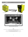
Connection Locations
Inside Plumbing Box
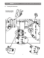
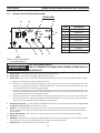
3.3 Plumbing Box Connections

26
SECTION 3 PCC14 PLUMBING BOX DESCRIPTION / INSTALLATION
Plasma Gas Hose From Torch
Shield Gas Hose From Torch
Pilot Arc Cable
From Power Supply
Pilot Arc Cable From Torch
Power / Coolant Supply
Hose From Torch
Power / Coolant Return
Hose From Torch
Coolant Supply Hose
Power Cables
Coolant Return Hose
ELECTRIC SHOCK CAN KILL!
TURN OFF PRIMARY INPUT POWER AT THE WALL DISCONNECT BOX BEFORE
MAKING ANY CONNECTIONS TO THE POWER SUPPLY.
DISCONNECT CURRENT SUPPLY AT WALL DISCONNECT BEFORE SERVICING
PLUMBING BOX.
• DO NOT OPERATE PLUMBING BOX WITH ANY COVERS REMOVED / OPEN.
• DO NOT TOUCH ANY TORCH FRONTEND PARTS WITH POWER ON.
• DO NOT ATTEMPT TO SERVICE UNLESS POWER HAS BEEN DISCONNECTED
AT THE WALL.
WARNING

27
SECTION 3 PCC14 PLUMBING BOX DESCRIPTION / INSTALLATION
1. Torch connections are rst made in the PCC-14 plumbing box. Remove the cover of the plumbing box to access input
and output connections . For both manual and mechanized torch applications, pass the torch lines through the
openings in the front of plumbing box and make connections as shown.
2
3
4
5
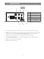
3.4 EPP-201 / EPP-360 Torch Connections to Plumbing Box
ELECTRIC SHOCK CAN KILL!
TURN OFF PRIMARY INPUT POWER AT THE WALL DISCONNECT BOX
BEFORE MAKING ANY CONNECTIONS TO THE PCC14.
WARNING
Coolant Supply
(Electrode Cable)
Coolant Return
(Electrode Cable)
Plasma Gas
Pilot Arc
Shield Gas
4
2
3
5
1
1 Shield Gas Hose
2 Electrode Cable / Coolant Return Hose
3 Plasma Gas Hose
4 Electrode Cable / Coolant Supply Hose
5 Pilot Arc Cable
1
Lines from torch
4
2
3
5
1

28
SECTION 3 PCC14 PLUMBING BOX DESCRIPTION / INSTALLATION
Chassis Ground
Note:
Chassis ground to be connected from PCC-14 Plumbing Box to either the cutting machine or to the chassis
of the power supply using the supplied ground wire.
(Ensure star washer is installed on the ground stud for the PCC-14 connections).
Hose connections should be wrench-tight.
Ensure plug of the switch lead is rmly locked in place. Then close hinged cover.
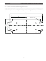
Interconnection Diagram - EPP-201/360
Electrode (-)
Pilot Arc (+)
Electrode (-)
Pilot Arc (+)

29
SECTION 3 PCC14 PLUMBING BOX DESCRIPTION / INSTALLATION
Connections to the Power Supply
1. A power output cable attaches to a large bolted connection labeled “Electrode”.
2. The Pilot Arc cable connects to a small threaded stud labeled “Pilot Arc”.
3. The Plasma Control Interface connects to the power supply. The PCC-14 Plumbing Box control cable connects to the
Plasma Control Interface.
4. A work cable connects to the "Work" terminal on the front-lower-left of the console. The other end is attached to the
cutting table or work piece.
Connections to the rear of the Plumbing Box
1. The Start, Cut & Shield gas hoses from the regulator panel attach to the rear of the plumbing box.
2. The Plumbing Box Control cable from the Plasma Control Interface connects to the amphenol receptacle labeled
“CONTROL CABLE FROM POWER SOURCE”.
Both power cables, the pilot arc cable and both coolant hoses enter the plumbing box from the rear and are connected
internally.
Connections to the Coolant Circulator
1. The coolant supply and return lines connect to the supply and return ttings on the coolant circulator.
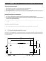
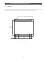
3.5 PCC-14 Plumbing Box Mounting Hole Locations
Install the PCC-14 Plumbing Box in an appropriate location so as to maintain adequate and unrestricted airow
into and out of the cabinetry. For permanent mounting refer to the gure below for mounting hole dimensions
in the base of this unit.
16.625"
(422.28 mm)
12.500"
(317.5 mm)
1.060"
(26.92 mm)
6.875"
(174.63 mm)
4.500"
(114.3 mm)
2.125"
(53.98 mm)
Page is loading ...
Page is loading ...
Page is loading ...

33
SECTION 3 Plasma Control InterfaCe DesCrIPtIon / InstallatIon
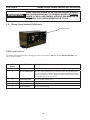
Weight : 17.0 lbs. (7.7 kg)
This unit is an integral component of the m3 Manual Gas Control Plasma
system used by an external controller (e.g. CNC) to interface with the PCC-
14 Plumbing Box. It controls all the sequencing required for handling the
plasma cutting/marking operation leaving the external controller with a
simple interface to the Plasma Control Interface (PCI).
3.6 General
3.7 Scope
The purpose of this manual is to provide the operator with all the informa-
tion required to install and operate the Plumbing Box & Plasma Control
Interface. Technical reference material is also provided to assist in trouble-
shooting.
Specications: Plasma Control Interface
15.50”
(393.7 mm)
6.59”
(167.4 mm)
13.67”
(347.2 mm)
PS
CNC PCC-14
E-STOP
1A
Page is loading ...
Page is loading ...
Page is loading ...
Page is loading ...
Page is loading ...
Page is loading ...
Page is loading ...
Page is loading ...
Page is loading ...
Page is loading ...
Page is loading ...
Page is loading ...
Page is loading ...
Page is loading ...
Page is loading ...
Page is loading ...
Page is loading ...
Page is loading ...
Page is loading ...
Page is loading ...
Page is loading ...
Page is loading ...
Page is loading ...
Page is loading ...
Page is loading ...
Page is loading ...
Page is loading ...
Page is loading ...
Page is loading ...
Page is loading ...
Page is loading ...
Page is loading ...
Page is loading ...
Page is loading ...
Page is loading ...
Page is loading ...
Page is loading ...
Page is loading ...
Page is loading ...
Page is loading ...
Page is loading ...
-
 1
1
-
 2
2
-
 3
3
-
 4
4
-
 5
5
-
 6
6
-
 7
7
-
 8
8
-
 9
9
-
 10
10
-
 11
11
-
 12
12
-
 13
13
-
 14
14
-
 15
15
-
 16
16
-
 17
17
-
 18
18
-
 19
19
-
 20
20
-
 21
21
-
 22
22
-
 23
23
-
 24
24
-
 25
25
-
 26
26
-
 27
27
-
 28
28
-
 29
29
-
 30
30
-
 31
31
-
 32
32
-
 33
33
-
 34
34
-
 35
35
-
 36
36
-
 37
37
-
 38
38
-
 39
39
-
 40
40
-
 41
41
-
 42
42
-
 43
43
-
 44
44
-
 45
45
-
 46
46
-
 47
47
-
 48
48
-
 49
49
-
 50
50
-
 51
51
-
 52
52
-
 53
53
-
 54
54
-
 55
55
-
 56
56
-
 57
57
-
 58
58
-
 59
59
-
 60
60
-
 61
61
-
 62
62
-
 63
63
-
 64
64
-
 65
65
-
 66
66
-
 67
67
-
 68
68
-
 69
69
-
 70
70
-
 71
71
-
 72
72
-
 73
73
-
 74
74


ESAB m3® Plasma Manual Gas Control Plasma System User manual
- Category
- Welding System
- Type
- User manual
- This manual is also suitable for
Ask a question and I''ll find the answer in the document
Finding information in a document is now easier with AI
in other languages
Related papers
Other documents
-
Lincoln 60 User manual
-
Lincoln Electric Pro-Cut 60 Operating instructions
-
-
 Thermal Dynamics iHC XT Operating instructions
-
-
Miller BDH Owner's manual
-
-
ESD CAN-PCC Owner's manual
-
 TE Connectivity 2388292 AMP Weld Smart E Controller User manual
-
Pyronix KX15DC-WE User manual

