United States Stove 2007 User manual
- Category
- Stoves
- Type
- User manual
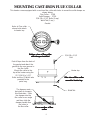
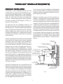
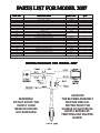
United States Stove 2007 is a pedestal heater designed to provide efficient and dependable warmth using wood as fuel. This durable heater features a cast-iron design and a painted jacket for lasting performance and style. It comes equipped with a solid damper to control airflow and a flue collar for easy chimney connection. With its efficient design, the heater helps conserve energy while offering a reliable source of heat for your indoor spaces.
United States Stove 2007 is a pedestal heater designed to provide efficient and dependable warmth using wood as fuel. This durable heater features a cast-iron design and a painted jacket for lasting performance and style. It comes equipped with a solid damper to control airflow and a flue collar for easy chimney connection. With its efficient design, the heater helps conserve energy while offering a reliable source of heat for your indoor spaces.


-
 1
1
-
 2
2
-
 3
3
-
 4
4
-
 5
5
-
 6
6
-
 7
7
-
 8
8
-
 9
9
-
 10
10
-
 11
11
-
 12
12
-
 13
13
-
 14
14
-
 15
15
-
 16
16


United States Stove 2007 User manual
- Category
- Stoves
- Type
- User manual
United States Stove 2007 is a pedestal heater designed to provide efficient and dependable warmth using wood as fuel. This durable heater features a cast-iron design and a painted jacket for lasting performance and style. It comes equipped with a solid damper to control airflow and a flue collar for easy chimney connection. With its efficient design, the heater helps conserve energy while offering a reliable source of heat for your indoor spaces.
Ask a question and I''ll find the answer in the document
Finding information in a document is now easier with AI
Related papers
-
United States Stove 1261 User manual
-
United States Stove B2350 Installation guide
-
-
-
-
-
-
-
-
Other documents
-
US Stove Company US1269E Owner's manual
-
United States Stove Company VG1820 Owner's manual
-
US Stove Company US1800E Owner's manual
-
Fireplace Plug Rectangular Fireplace Plug BRK-FP-05-01 Specification
-
Pleasant Hearth HWS-224172MH User manual
-
King 2016E Owner's manual
-
Ashley Hearth Products AW1820E Owner's manual
-
MHSC WR2500X02 Owner's manual
-
Vermont Castings WR2500X02 Owner's manual
-