Tripp Lite SMX1050SLT User manual

Category
Uninterruptible power supplies (UPSs)
Type
User manual

This manual is also suitable for

Owner’s Manual
1111 W. 35th Street Chicago, IL 60609 USA
Customer Support: (773) 869-1234 • www.tripplite.com
Important Safety Instructions
2
Quick Installation
3
Basic Operation
5
Storage and Service
8
Español
Copyright © 2006 Tripp Lite. All rights reserved. SmartPro
®
is a trademark of Tripp Lite
SmartPro
®
SLT
Intelligent, Line-Interactive UPS System
• 220/230/240V Pure Sine Wave Input/Output
Not suitable for mobile applications.
9
Battery Replacement
8
Français
17
Optional Installation
4
Deutsch
25
PyccŞèé
33
200603172 93-2443 SmartPro update OM.qxd 5/16/2006 3:15 PM Page 1
2
Important Safety Instructions
SAVE THESE INSTRUCTIONS
This manual contains important instructions that should be followed during the installation, operation
and storage of all Tripp Lite UPS Systems. Failure to heed these warnings will void your warranty.
UPS Location Warnings
• Use caution when lifting UPS.
• Install your UPS indoors, away from excess moisture or heat, dust or direct sunlight.
• For best performance, the ambient temperature near your UPS should be between 0° C and
40° C (between 32° F and 104° F).
• Leave adequate space around all sides of the UPS for proper ventilation. Do not obstruct its
vents or fan openings.
UPS Connection Warnings
• The UPS contains its own energy source (battery). The output terminals may be live even
when the UPS is not connected to an AC supply.
• Connect your UPS to a properly grounded AC power outlet. Do not modify the UPS’s plug
in a way that would eliminate the UPS’s connection to ground. Do not use adapters that
eliminate the UPS’s connection to ground.
• Do not plug your UPS into itself; this will damage the UPS and void your warranty.
• If you are connecting your UPS to a motor-powered AC generator, the generator must provide
filtered, frequency-regulated computer-grade output.
Equipment Connection Warnings
• Do not use Tripp Lite UPS Systems for life support applications in which a malfunction or
failure of a Tripp Lite UPS System could cause failure or significantly alter the performance
of a life-support device.
• Do not connect surge suppressors or extension cords to the output of your UPS. This might
overload the UPS and will void the surge suppressor and UPS warranties.
Battery Warnings
• Batteries can present a risk of electrical shock and burn from high short-circuit current.
Observe proper precautions. Do not dispose of the batteries in a fire. Do not open the UPS or
batteries. Do not short or bridge the battery terminals with any object. Unplug and turn off the
UPS before performing battery replacement. Use tools with insulated handles. There are no
user-serviceable parts inside the UPS. Battery replacement should be performed only by
authorized service personnel using the same number and type of batteries (sealed Lead-Acid).
The batteries are recyclable. Refer to your local codes for disposal requirements. Tripp Lite
offers a complete line of UPS System Replacement Battery Cartridges (R.B.C.). Visit Tripp
Lite on the Web at www.tripplite.com to locate the specific replacement battery for your UPS.
200603172 93-2443 SmartPro update OM.qxd 5/16/2006 3:15 PM Page 2
3
230V
220V
240V
230V
Quick Installation
With the UPS disconnected from
utility power, use a small tool to
set the Voltage Dip Switches to
match your input voltage. (All
models are preset to the 230V
setting.)
Insert a user-supplied power cord
(with country-specific plug) into
the UPS System's AC input
receptacle. Plug the cord into
an AC wall outlet.
NOTE! after you plug the UPS into a live AC outlet,
the UPS (in “Standby” mode) will automatically
charge its batteries,* but will not supply power to its
outlets until it is turned ON.
* The BATTERY CHARGE LED will be the only LED illuminated.
Find one of the power cords that
came with the UPS. Insert the
cord’s female plug into
computer’s AC input. Insert the
cord’s male plug into any UPS
female output receptacle.
Plug your equipment into the UPS.
Plug your equipment into the UPS. Repeat Step 3
above using the additional power cord(s) that came
with the UPS.
Note: Additional interconnection cords (C13 to
C14) are available from Tripp Lite. Call 773-869-
1234 (Part # P004-006).
Your UPS is designed to support computer equipment only. You will
overload the UPS if the total VA ratings for all the equipment you
connect exceeds UPS output capacity. To find your equipment’s VA
ratings, look on their nameplates. If the equipment is listed in amps,
multiply the number of amps by 240 to determine VA. (Example:
1 amp × 240 = 240 VA). If you are unsure if you have overloaded your
UPS's outlets, see “OUTPUT LOAD LEVEL” LED description.
Turn the UPS ON.
Press and hold the “ON/OFF/STANDBY” button for
one second. The alarm will beep once briefly after one
second has passed. Release the button.
1
1
2
5
3
4
5
2
3
4
240V
230V
220V
230V
SMX750SLT SMX1050SLT &
SMX1500SLT
200603172 93-2443 SmartPro update OM.qxd 5/16/2006 3:15 PM Page 3
Optional Installation
These connections are optional. Your UPS will function
properly without these connections.
USB and RS-232 Serial
Communications
Use the included USB cable (see ) and/or DB9 serial
cable (see ) to connect the communication port on
your computer to the communication port of your
UPS. Install on your computer the Tripp Lite
PowerAlert Software appropriate to your computers
operating system.
Telephone/Network Protection Jacks
Your UPS has jacks that protect against surges over a
telephone line or a network dataline. Using telephone
or network data cables, connect your wall jack to the
UPS jack marked “IN.” Connect your equipment to
the UPS jack marked “OUT.” Make sure the
equipment you connect to the UPS's jacks is also
protected against surges on the AC line.
Not compatible with PoE (Power Over Ethernet) applications.
1b
1a
4
1b
1a
2
1
2
200603172 93-2443 SmartPro update OM.qxd 5/16/2006 3:15 PM Page 4
5
“ON/OFF/STANDBY” Button
To turn the UPS ON: with the UPS plugged into a live AC wall outlet*, press
and hold the “ON/OFF/STANDBY” button for one second.** Release the
button. If utility power is absent, you can “cold-start” the UPS (i.e.: turn it ON
and supply power for a limited time from its batteries***) by pressing and
holding the “ON/OFF/STANDBY” button for one second.**
To turn the UPS OFF: with the UPS ON and receiving utility power, press
and hold the “ON/OFF/STANDBY” button for one second.** Then unplug
the UPS from the wall outlet. The UPS will be completely OFF.
* After you plug the UPS into a live AC outlet, the UPS (in ”Standby” mode) will automatically charge
its batteries, but will not supply power to its outlets until it is turned ON. ** The alarm will beep once
briefly after the indicated interval has passed. *** If fully charged.
“MUTE/TEST” Button
To Silence (or “Mute”) UPS Alarms: briefly press and release the
MUTE/TEST button.*
To Run a Self-Test: with your UPS plugged in and turned ON, press and hold
the MUTE/TEST button. Continue holding the button until the alarm beeps sev-
eral times and the UPS performs a self test. See “Results of a Self-Test” below.
Note: you can leave connected equipment on during a self-test. Your UPS, how-
ever, will not perform a self-test if the UPS is not turned on (see
“ON/OFF/STANDBY” Button description).
CAUTION! Do not unplug your UPS to test its batteries. This will remove
safe electrical grounding and may introduce a damaging surge into your
network connections.
Results of a Self-Test: The test will last approximately 10 seconds as the
UPS switches to battery to test its load capacity and battery charge.
If the “OUTPUT LOAD LEVEL” LED remains lit red and the alarm
continues to sound after the test, the UPS’s outlets are overloaded. To
clear the overload, unplug some of your equipment and run the self-test
repeatedly until the “OUTPUT LOAD LEVEL” LED is no longer lit red
and the alarm is no longer sounding.
CAUTION! Any overload that is not corrected by the user immedi-
ately following a self-test may cause the UPS to shut down and cease
supplying output power in the event of a blackout or brownout.
If the “BATTERY WARNING” LED remains lit and the alarm continues
to sound after the test, the UPS batteries need to be recharged or
replaced. Allow the UPS to recharge continuously for 12 hours, and
repeat the self-test. If the LED remains lit, contact Tripp Lite for service.
If your UPS requires battery replacement, visit www.tripplite.com to
locate the specific Tripp Lite replacement battery for your UPS.
* The alarm will beep once briefly after the indicated interval has passed.
Basic Operation
Buttons (Front Panel)
200603172 93-2443 SmartPro update OM.qxd 5/16/2006 3:15 PM Page 5
Basic Operation
continued
Indicator Lights (Front Panel)
All Indicator Light descriptions apply when the UPS is plugged into a wall
outlet and turned ON.
“POWER” LED: this green LED lights continuously when the UPS is ON and
supplying connected equipment with AC power from a utility source. The LED
flashes and an alarm sounds (4 short beeps followed by a pause) to indicate the
UPS is operating from its internal batteries during a blackout or severe
brownout. If the blackout or severe brownout is prolonged, you should save
files and shut down your equipment since internal battery power will eventual-
ly be depleted. See “BATTERY CHARGE” LED description below.
“VOLTAGE CORRECTION” LED: this green LED lights continuously
whenever the UPS is automatically correcting high or low AC voltage on the
utility line without the assistance of battery power. The UPS will also emit a
slight clicking noise. These are normal, automatic operations of the UPS, no
action is required on your part.
“OUTPUT LOAD LEVEL” LEDs: the LEDs indicate the approximate elec-
trical load of equipment connected to the UPS's AC outlets. They will turn from
green (light load) to yellow (medium load) to red (overload). If the LED is red
(either illuminated continuously or flashing), clear the overload immediately by
unplugging some of your equipment from the outlets until the LED changes
from red to yellow (or green). CAUTION! Any overload that is not corrected
by the user immediately may cause the UPS to shut down and cease supplying
output power in the event of a blackout or brownout.
“BATTERY CHARGE” LEDs: when the UPS is operating from utility power,
the LEDs indicate the approximate charge state of the UPS's internal batteries:
red indicates the batteries are beginning to charge; yellow indicates the batter-
ies are roughly midway through charging; and green indicates the batteries are
fully charged. When the UPS is operating from battery power during a blackout
or severe brownout, the LEDs indicate the approximate amount of energy
(ultimately affecting runtime) which the UPS’s batteries will provide: red indi-
cates a low level of energy; yellow indicates a medium level of energy; and
green indicates a high level of energy. Since the runtime performance of all UPS
batteries will gradually deplete over time, it is recommended that you periodi-
cally perform a self-test (see MUTE/TEST Button description) to determine the
energy level of your UPS batteries BEFORE a blackout or severe brownout
occurs. During a prolonged blackout or severe brownout, you should save files
and shut down your equipment since battery power will eventually be depleted.
When the red LED illuminates and an alarm sounds continuously, it indicates
the UPS's batteries are nearly out of power and UPS shutdown is imminent.
“BATTERY WARNING” LED: this LED lights red and an alarm sounds
intermittently after you initiate a self test (See “MUTE/TEST” Button descrip-
tion) to indicate the UPS batteries need to be recharged or replaced. Allow the
UPS to recharge continuously for 12 hours, and repeat the self-test. If the LED
continues to light, contact Tripp Lite for service. If your UPS requires battery
replacement, visit www.tripplite.com to locate the specific Tripp Lite replace-
ment battery for your UPS.
6
200603172 93-2443 SmartPro update OM.qxd 5/16/2006 3:15 PM Page 6
7
Basic Operation
continued
Other UPS Features (Rear Panel)
AC Receptacles: Your UPS features IEC-320-C13 outlets. These output
receptacles provide your connected equipment with AC line power during
normal operation and battery power during blackouts and brownouts. The UPS
protects equipment connected to these receptacles against damaging surges and
line noise.
Communications Ports (USB or RS-232): These ports connect your UPS to
any workstation or server. Use with Tripp Lite’s PowerAlert Software and
included cables to enable your computer to automatically save open files and
shut down equipment during a blackout. Also use PowerAlert Software to mon-
itor a wide variety of AC line power and UPS operating conditions. Consult
your PowerAlert Software manual or contact Tripp Lite Customer Support for
more information. See “USB and RS-232 Serial Communications” in the
“Optional Installation” section for installation instructions.
Telephone/Network Protection Jacks: These jacks protect your equipment
against surges over a telephone/network data line. Connecting your equipment
to these jacks is optional. Your UPS will work properly without this connection.
Not compatible with PoE (Power Over Ethernet) applications.
Voltage DIP Switches: These switches enable the UPS to be set to match
actual input voltage. If the Voltage DIP Switches are set above or below input
voltage, the UPS will treat the input as a continuous overvoltage or undervolt-
age condition, and will automatically adjust input voltage to match the Voltage
DIP Switch setting. This will cause constant, unnecessary wear on the UPS.
Note: The Voltage DIP Switches must be set with the UPS turned OFF and
disconnected from utility power. If the switches are set while the UPS is
connected to utility power, the setting will not take effect.
Accessory Slot: Remove the small cover panel from this slot to install option-
al accessories to remotely monitor and control your UPS. Refer to your acces-
sory’s manual for installation instructions. Contact Tripp Lite Customer
Support at (773) 869-1234 for more information, including a list of available
SNMP, network management and connectivity products.
Input Breaker (SMX1500SLT): Protect your electrical circuit from overcur-
rent draw from the UPS load. If this breaker trips, remove some of the load,
then reset by pressing the breaker in.
Fan: The fan cools the UPS's internal components. It operates only when the
UPS is in battery backup mode, is charging its batteries or is carrying a heavy
electrical load.
230V
220V
240V
230V
240V
230V
220V
230V
200603172 93-2443 SmartPro update OM.qxd 5/16/2006 3:15 PM Page 7
8
Storage and Service
Storage
Before storing your UPS, turn it completely OFF: with the UPS ON and receiving utility power,
press and hold the “ON/OFF/STANDBY” button for one second (an alarm will beep once briefly
after the interval has passed); then, unplug the UPS from the wall outlet. If you store your UPS for
an extended period of time, recharge the UPS batteries once every three months: plug the UPS into
a wall outlet; allow it to charge for 12 hours; and then unplug it and place it back in storage. Note:
after you plug the UPS in, it will automatically begin charging its batteries; however, it will not sup-
ply power to its outlets (see Quick Installation section). If you leave your UPS batteries discharged
for an extended period of time, they will suffer a permanent loss of capacity.
Service
Before returning your UPS for service, follow these steps:
1. Review the installation and operation instructions in this manual to ensure that the service
problem does not originate from a misreading of the instructions. Also, check that the UPS
System’s circuit breaker(s) are not tripped. This is the most common cause of service inquiries
which can be easily remedied by following the resetting instructions in this manual.
2. If the problem continues, do not contact or return the UPS to the dealer. Instead, call Tripp Lite
at (773) 869-1233. A service technician will ask for the UPS's model number, serial number
and purchase date and will attempt to correct the problem over the phone.
3. If the problem requires service, the technician will issue you a Returned Material Authorization
(RMA) number, which is required for service. If you require packaging, the technician can
arrange to send you proper packaging. Securely pack the UPS to avoid damage during ship-
ping. Do not use Styrofoam beads for packaging. Any damages (direct, indirect, special, inci-
dental or consequential) to the UPS incurred during shipment to Tripp Lite or an authorized
Tripp Lite service center is not covered under warranty. UPS Systems shipped to Tripp Lite or
an authorized Tripp Lite service center must have transportation charges prepaid. Mark the
RMA number on the outside of the package. If the UPS System is within the 2-year warranty
period, enclose a copy of your sales receipt. Return the UPS for service using an insured car-
rier to the address given to you by the Tripp Lite service technician.
Battery Replacement
Battery Replacement Door: Under normal conditions, the original battery in your UPS will last
several years. Battery replacement should be performed only by qualified service personnel. Refer
to “Battery Warnings” in the Safety section. Should your UPS require battery
replacement, visit Tripp Lite on the Web at www.tripplite.com/support/bat-
tery/index.cfm to locate the specific replacement battery for your UPS.
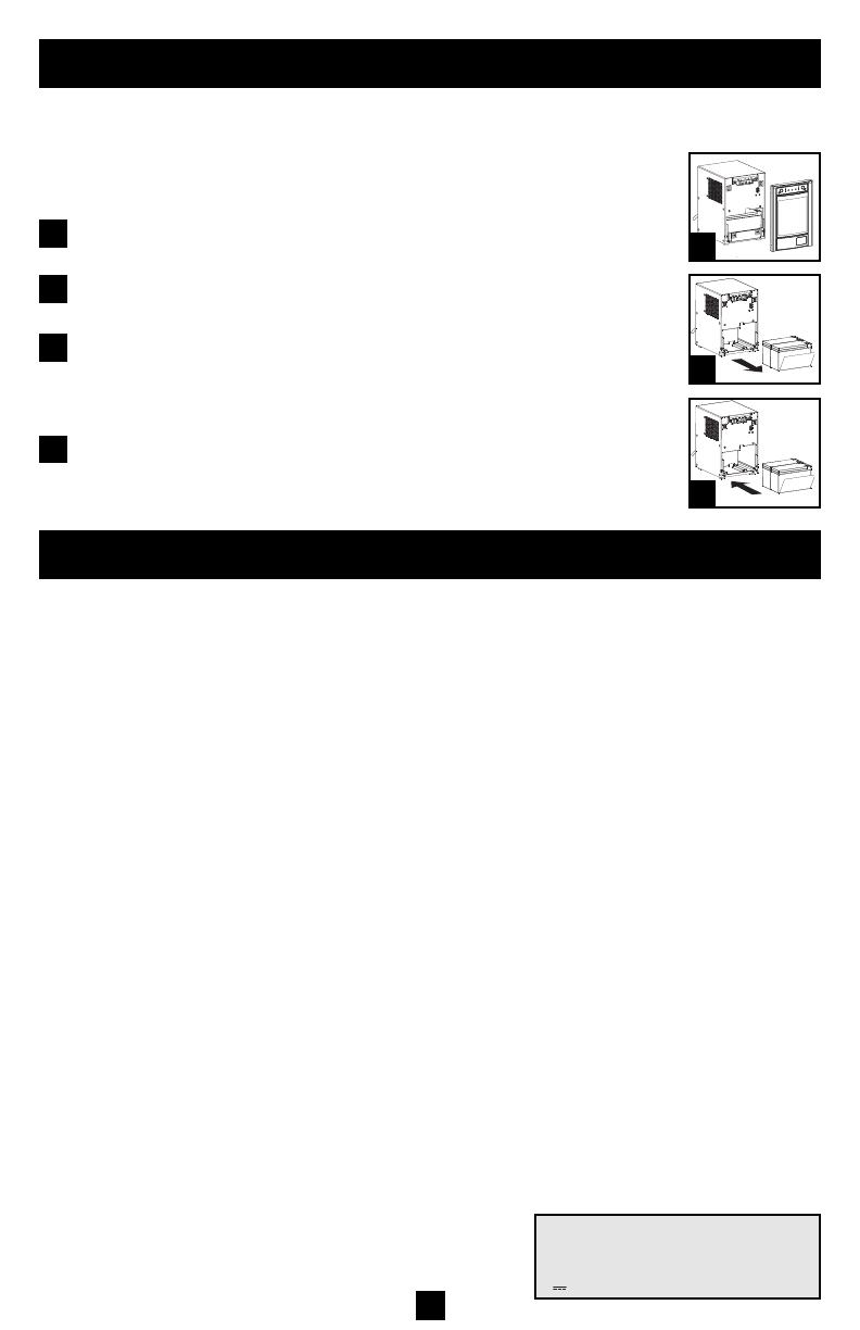
Carefully pull the front panel away from the UPS.
Place front panel on top of the unit. Remove the battery support bar.
Remove old batteries.
Carefully pull the batteries from the UPS and disconnect them.
Connect new batteries.
Connect the new batteries in exactly the same manner as the old ones: pos-
itive (red) connectors together and negative (black) connectors together.
Carefully push batteries back into the UPS.
Reassemble UPS.
Reinstall the battery support bar and replace the front panel.
1
2
3
1
2
3
4
Regulatory Compliance Identification Numbers
For the purpose of regulatory compliance certifications and identification, your Tripp Lite product has been assigned a
unique series number. The series number can be found on the product nameplate label, along with all required approval
markings and information. When requesting compliance information for this product, always refer to the series number.
The series number should not be confused with the marking name or model number of the product.
This product designed and engineered in the USA.
Note on Labeling
Two symbols are used on the label.
V~ : AC Voltage
V : DC Voltage
200603172 93-2443 SmartPro update OM.qxd 5/16/2006 3:15 PM Page 8
1111 W. 35th Street, Chicago, IL 60609 USA
773.869.1234 (USA) • 773.869.1212 (International)
www.tripplite.com
200603172 93-2443_EN
  • Page 1 1
  • Page 2 2
  • Page 3 3
  • Page 4 4
  • Page 5 5
  • Page 6 6
  • Page 7 7
  • Page 8 8
  • Page 9 9

Tripp Lite SMX1050SLT User manual

Category
Uninterruptible power supplies (UPSs)
Type
User manual
This manual is also suitable for

Ask a question and I''ll find the answer in the document

Finding information in a document is now easier with AI