Page 2
For technical questions, please call 1-800-444 3353. Item 67853
4. Setupanduseonlyonaat,level,
well-ventilated surface.
5. Use only lubricants and fuel recommended in the
enginemanualorintheSpecicationschartof
this manual.
6. Wear ANSI-approved safety goggles, heavy-duty work
gloves, and dust mask/respirator during set up.
Engine Precautions
Follow engine precautions and instructions in the included
engine instruction manual.
Operating Precautions
1. CARBON MONOXIDE HAZARD
Using an engine indoors CAN KILL
YOU IN MINUTES.
Engine exhaust contains carbon
monoxide. This is a poison you cannot
see or smell.
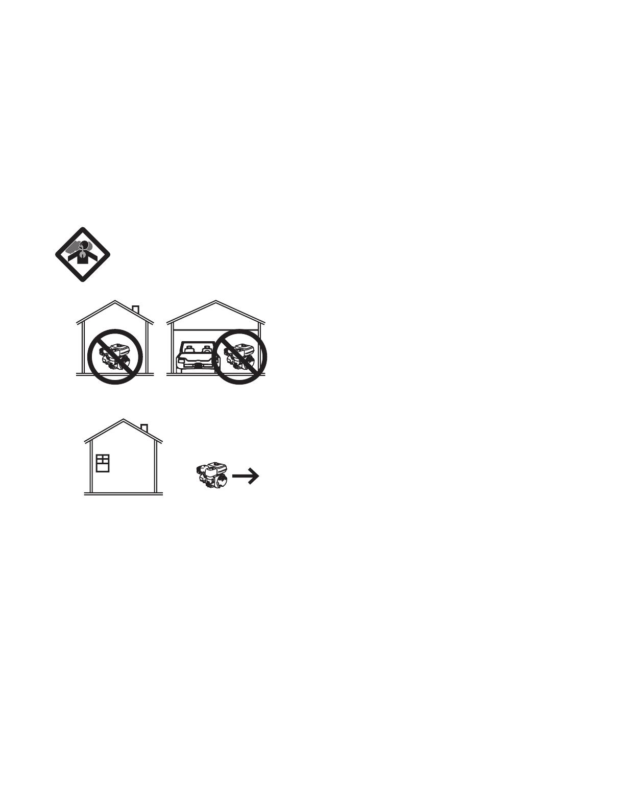
NEVER use inside a home or garage, EVEN IF doors
and windows are open.
Only use OUTSIDE and far away from windows, doors,
and vents.
2. Keep children away from the equipment, especially
while it is operating.
3. FireHazard!DonotllgastankwhileCompressor
engine is running. Do not operate if gasoline has been
spilled. Clean spilled gasoline before starting engine.
Donotoperatenearpilotlightoropename.
4. Do not touch Compressor engine during use. Let
engine cool down after use.
5. Neverstorefuelorotherammablematerialsnear
the Compressor engine.
6. Only use a suitable means of transport and lifting
deviceswithsufcientweightbearingcapacitywhen
transporting the Compressor.
7. Secure the Compressor on transport vehicles to
prevent the tool from rolling, slipping, and tilting.
8. Industrial applications must follow OSHA requirements.
9. Do not leave the equipment unattended when it is
running. Turn off the equipment (and remove safety
keys, if available) before leaving the work area.
10. Wear ANSI-approved safety glasses, hearing
protection, and NIOSH-approved dust mask/respirator
under a full face shield along with steel-toed work boots
during use.
11. People with pacemakers should consult their
physician(s)beforeuse.Electromagneticeldsin
close proximity to a heart pacemaker could cause
pacemaker interference or pacemaker failure. Caution
is necessary when near the engine’s magneto or
recoil starter.
12. Use only accessories that are recommended by Harbor
Freight Tools for your model. Accessories that may
be suitable for one piece of equipment may become
hazardous when used on another piece of equipment.
13. Do not operate in explosive atmospheres, such
asinthepresenceofammableliquids,gases,or
dust. Gasoline-powered engines may ignite the dust
or fumes.
14. Stay alert, watch what you are doing and use common
sense when operating this piece of equipment. Do not
use this piece of equipment while tired or under the
inuenceofdrugs,alcoholormedication.
15. Do not overreach. Keep proper footing and balance at
all times. This enables better control of the equipment
in unexpected situations.
16. Dress properly. Do not wear loose clothing or jewelry.
Keep hair, clothing and gloves away from moving parts.
Loose clothes, jewelry or long hair can be caught in
moving parts.
17. Parts, especially exhaust system components, get very
hot during use. Stay clear of hot parts.
18. Do not cover the engine or equipment during operation.
19. Keep the equipment, engine, and surrounding area
clean at all times.
20. Use the equipment, accessories, etc., in accordance
with these instructions and in the manner intended for
the particular type of equipment, taking into account the
working conditions and the work to be performed. Use
of the equipment for operations different from those
intended could result in a hazardous situation.
21. Do not operate the equipment with known leaks in the
engine’s fuel system.
22. This product contains or, when used, produces a
chemical known to the State of California to cause
cancer and birth defects or other reproductive harm.
(California Health & Safety Code § 25249.5, et seq.)
23. When spills of fuel or oil occur, they must be cleaned
upimmediately.Disposeofuidsandcleaning
materials as per any local, state, or federal codes
and regulations. Store oil rags in a bottom-ventilated,
covered, metal container.