
INSTRUCTION MANUAL
MODEL W1708
Disc Sander
Phone: 1-360-734-3482 • On-Line Technical Support: [email protected]
COPYRIGHT © September, 2003 BY WOODSTOCK INTERNATIONAL, INC.
WARNING: NO PORTION OF THIS MANUAL MAY BE REPRODUCED IN ANY SHAPE OR FORM WITHOUT
THE WRITTEN APPROVAL OF WOODSTOCK INTERNATIONAL, INC.
Printed in China

WARNING
Some dust created by power sanding, sawing,
grinding, drilling, and other construction activities
contains chemicals known to the State of California
to cause cancer, birth defects or other reproductive
harm. Some examples of these chemicals are:
• Lead from lead-based paints.
• Crystalline silica from bricks, cement, and
other masonry products.
• Arsenic and chromium from chemically
treated lumber.
Your risk from these exposures varies, depending on
how often you do this type of work. To reduce your
exposure to these chemicals: work in a well
ventilated area, and work with approved safety
equipment, such as those dust masks that are
specially designed to filter out microscopic
particles.

ASSEMBLY
OPERATIONS
MAINTENANCE
PARTS
ADJUSTMENTS
SAFETY
INTRODUCTION
USE THE QUICK GUIDE PAGE LABELS TO SEARCH OUT INFORMATION FAST!
CONTENTS
INTRODUCTION ............................................................................................2
About Your New Disc Sander................................................................................2
Woodstock Service and Support ............................................................................2
Warranty and Returns ........................................................................................3
Specifications ..................................................................................................3
SAFETY FIRST!..............................................................................................4
Standard Safety Instructions ................................................................................4
Disc Sander Components ....................................................................................6
Additional Safety Instructions for Disc Sanders ........................................................7
110V Operation ................................................................................................8
Extension Cords ................................................................................................8
Grounding ......................................................................................................8
ASSEMBLY ..................................................................................................9
Overview ........................................................................................................9
Box Contents....................................................................................................9
Shop Preparation ..............................................................................................9
Cleaning Machine ............................................................................................10
ADJUSTMENTS ............................................................................................11
General Information ........................................................................................11
Adjusting Table ..............................................................................................11
Table Tilt ......................................................................................................12
Replacing the Sandpaper ..................................................................................12
Disc Sanding ..................................................................................................13
OPERATIONS ..............................................................................................13
Test Run........................................................................................................13
Miter Sanding ................................................................................................14
Angle Sanding ................................................................................................14
Table............................................................................................................15
General ........................................................................................................15
Lubrication ....................................................................................................15
MAINTENANCE ............................................................................................15
PARTS ......................................................................................................16
Closure ........................................................................................................16
W1708 Disc Sander ..........................................................................................17
Parts List ......................................................................................................18

INTRODUCTION
-2-
Your new SHOP FOX
®
Disc Sander has been specially designed to provide many years of trouble-free
service. Close attention to detail, ruggedly built parts and a rigid quality control program assure safe
and reliable operation.
The Model W1708 is a very versatile and easy to use disc sander. This machine can perform a wide
variety of sanding operations. This disc sander features a 1 HP motor, a tilting cast iron table, a miter
gauge, a built in 2" dust port, and a 12" sanding disc.
Woodstock International, Inc. is committed to customer satisfaction in providing this manual. It is our
intent to make sure all the information necessary for safety, ease of assembly, practical use and
durability of this product be included.
We stand behind our machines! In the event that a defect is found, parts are missing or questions arise
about your machine, please contact Woodstock International Service and Support at 1-360-734-3482 or
send e-mail to: [email protected]
Our knowledgeable staff will help you troubleshoot
problems, send out parts or arrange warranty returns.
If you need the latest edition of this manual, you can download it from http://www.shopfox.biz.
If you still have questions after reading the latest manual, or if you have comments please contact us at:
Woodstock International, Inc.
Attn: Technical Support Department
P.O. Box 2309
Bellingham, WA 98227
Woodstock Service and Support
About Your New Disc Sander
INTRODUCTION

INTRODUCTION
-3-
INTRODUCTION
Woodstock International, Inc. warrants all SHOP FOX
®
machinery to be free of defects from
workmanship and materials for a period of 2 years from the date of original purchase by the original
owner. This warranty does not apply to defects due directly or indirectly to misuse, abuse, negligence
or accidents, lack of maintenance, or to repairs or alterations made or specifically authorized by
anyone other than Woodstock International, Inc.
Woodstock International, Inc. will repair or replace, at its expense and at its option, the SHOP FOX
®
machine or machine part which in normal use has proven to be defective, provided that the original
owner returns the product prepaid to the SHOP FOX
®
factory service center or authorized repair
facility designated by our Bellingham, WA office, with proof of their purchase of the product within 2
years, and provides Woodstock International, Inc. reasonable opportunity to verify the alleged defect
through inspection. If it is determined there is no defect, or that the defect resulted from causes not
within the scope of Woodstock International Inc.'s warranty, then the original owner must bear the
cost of storing and returning the product.
This is Woodstock International, Inc.'s sole written warranty and any and all warranties that may be
implied by law, including any merchantability or fitness, for any particular purpose, are hereby
limited to the duration of this written warranty. We do not warrant that SHOP FOX
®
machinery
complies with the provisions of any law or acts. In no event shall Woodstock International, Inc.'s
liability under this warranty exceed the purchase price paid for the product, and any legal actions
brought against Woodstock International, Inc. shall be tried in the State of Washington, County of
Whatcom. We shall in no event be liable for death, injuries to persons or property or for incidental,
contingent, special or consequential damages arising from the use of our products.
Every effort has been made to ensure that all SHOP FOX
®
machinery meets high quality and durability
standards. We reserve the right to change specifications at any time because of our commitment to
continuously improve the quality of our products.
Specifications
Motor Size..............................................................................1 HP, 110V, 60 Hz
Motor Speed ......................................................................................1725 RPM
Amps ....................................................................................................10 A
Sanding Disc ..............................................................................................12"
Disc Speed ........................................................................................1725 RPM
Table ..........................................................................................17
1
/4" x 8
1
/4"
Power Transfer................................................................................Direct Drive
Bearings ..............................................................Sealed, Permanantly Lubricated
Switch ....................................................Paddle ON/OFF Switch, w/Safety Lock Key
Machine Weight ......................................................................................68 lbs
Warranty and Returns

SAFETY
-4-
READ MANUAL BEFORE OPERATING MACHINE.
FAILURE TO FOLLOW INSTRUCTIONS BELOW WILL
RESULT IN PERSONAL INJURY.
1. Thoroughly read the instruction manual before operating your machine. Learn the applications,
limitations and potential hazards of this machine. Keep manual in a safe, convenient place for
future reference. Make sure any other operators have read and understand the manual as well.
2. Keep work area clean and well lighted. Clutter and inadequate lighting invite potential hazards.
3. Ground all tools. If a machine is equipped with a three-prong plug, it must be plugged into a
three-hole grounded electrical outlet or grounded extension cord. If using an adapter to aid in
accommodating a two-hole receptacle, ground using a screw to a known ground.
4. Wear eye protection at all times. Use safety glasses with side shields or safety goggles that meet
the national safety standards, while operating this machine.
5. Avoid dangerous environments. Do not operate this machine in wet or open flame environments.
Airborne dust particles could cause an explosion and severe fire hazard.
6. Ensure all guards are securely in place and in working condition.
7. Make sure switch is in the “OFF” position before connecting power to machine.
8. Keep work area clean, free of clutter, grease, etc.
9. Keep children and visitors away. Visitors should be kept at a safe distance away while operating.
10. Childproof workshop with padlocks, master switches or by removing starter keys.
11. Disconnect machine when cleaning, adjusting or servicing.
12. Do not force the machine. The machine will do a safer and better job if it does the work.
Indicates an imminently hazardous situation which, if not avoided, WILL
result in death or serious injury.
Indicates a potentially hazardous situation which, if not avoided, COULD
result in death or serious injury.
Indicates a potentially hazardous situation which, if not avoided, MAY
result in minor or moderate injury, MAY result in property damage.
This symbol is used to alert the user to useful information about proper
operation of the equipment.
NOTICE
Standard Safety Instructions
SAFETY FIRST!

SAFETY
-5-
13. Use the correct tool. Do not force the tool or attachment to do a job for which it was not
designed.
14. Wear proper apparel. Do not wear loose clothing, gloves, jewelry, keep long hair tied up, etc.
15. Remove adjusting keys and wrenches. Before turning the machine on, make a habit of checking
that all adjusting keys and wrenches have been removed before turning the machine ON.
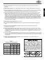
16. Use proper extension cord. Examine the extension cord to ensure it is in good condition. Use
Table 1 below to determine the correct length and gauge of extension cord needed for your
particular needs. The amp rating of the motor can be found on its nameplate. If the motor is dual
voltage, be sure to use the amp rating for the voltage you will be using. If you use an extension
cord with an undersized gauge or one that is too long, excessive heat will be generated within the
circuit increasing the chance of a fire or damage to the circuit. Never use an extension cord that
does not have a ground pin and connected ground wire. Immediately replace an extension cord if
it shows any signs of damage.
17. Keep stable footing and balance at all times.
18. Do not leave machine unattended. Wait until it comes to a complete stop before leaving the
area.
19. Perform machine maintenance and care. Follow lubrication and accessory attachment
instructions in the manual.
20. Keep machine away from open flame. Operating machines near pilot lights and/or open flames
creates a high risk if dust is dispersed in the area. Dust particles and an ignition source may cause
an explosion. Do not operate the machine in high-risk areas, including but not limited to, those
mentioned above.
21. If at any time you are experiencing difficulties performing the intended operation, stop using the
machine! Then contact our Service Department or ask a qualified expert how the operation should
be performed.
22. Habits—good and bad—are hard to break. Develop good habits in your shop and safety will
become second-nature to you.
Operating this equipment creates the
potential for flying debris to cause eye
injury. Always wear safety glasses or
goggles when operating equipment.
Everyday glasses or reading glasses only
have impact resistant lenses, they are not
safety glasses. Be certain the safety glasses
you wear meet the appropriate standards of
the American National Standards Institute
(ANSI).
Length And Gauge
Amp Rating 25ft 50ft 100ft
0-6 #16 #16 #16
7-10 #16 #16 #14
11-12 #16 #16 #14
13-16 #14 #12 #12
17-20 #12 #12 #10
21-30 #10 #10 No
Table 1
Extension Cord Requirements

SAFETY
-6-
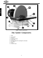
Figure 1. Machine Identification.
1. Base
2. Miter Gauge
3. Dust Port
4. Table Lock Handle
5. Work Table
6. Precision Ground Disc (Sanding Disc Attached)
7. Disc Guard
8. Motor
9. ON/OFF Switch
Disc Sander Components
2
7
8
6
5
4
3
1
9

SAFETY
-7-
USE this and other machinery with caution
and respect. No list of safety guidelines can
be complete. Every shop environment is
different. Always consider safety first, as it
applies to your individual working
conditions. Failure to follow guidelines
could result in serious personal injury,
damage to equipment or poor work results.
1. Always disconnect the machine from the power source when moving or servicing the disc
sander!
2. All inspections, adjustments, and maintenance MUST be done with the power off and the
power cord unplugged. Wait for disc to come to a complete stop.
3. Always keep your fingers away from the moving disc. Serious personal injury could occur.
4. Never operate this disc sander if the disc is worn or damaged. Inspect disc before each use.
Worn discs stress the motor and can burn the workpiece.
5. Never use excessive force when sanding. This causes motor overload and increases the chance of
fingers slipping into the disc.
6. Always feed the material into the portion of the disc that is spinning down toward the table.
7. Always place material flat on the surface of the table before sanding.
8. If there is any doubt as to the stability of the material to be sanded, do not sand it.
9. If you ever experience difficulties performing the intended sanding operation, stop using the
disc sander! Then contact our service department or ask a qualified expert how the operation
should be performed.
10. Always wear a dust mask or respirator when sanding even if you have a reliable method of dust
collection.
11. Sanding dust from some woods may be toxic or cause an allergic reaction. Be sure to wear an
appropriate respirator when working around wood dust. Make sure there is adequate ventilation or
a constant source of fresh air. The dust from some species of wood can be toxic to some people.
Be sure to research the dangers of the specific species of wood you are working with.
READ and understand this
entire instruction manual
before performing any
operations with your
machine. Serious personal
injury may occur if safety and
operational information is not
understood and followed.
INSTRUCTION MANUAL
MODEL W1708
Disc Sander
Phone: 1-360-734-3482 • On-Line Technical Support: [email protected]
COPYRIGHT © August, 2003 BY WOODSTOCK INTERNATIONAL, INC.
WARNING: NO PORTION OF THIS MANUAL MAY BE REPRODUCED IN ANY SHAPE OR FORM WITHOUT
THE WRITTEN APPROVAL OF WOODSTOCK INTERNATIONAL, INC.
Printed in China
Additional Safety Instructions for Disc Sanders

SAFETY
-8-
When it is necessary to use an extension cord,
follow the guidelines below:
• Use cords rated for Standard Service
• Never use cords longer than 100 feet
• Use cords with 16 gauge wire
• Always use cords with a grounding pin
• Never use damaged cords
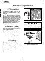
This machine must be grounded! If your outlet
does not accommodate a ground pin (Figure
2), have the outlet replaced by a qualified
electrician or have an appropriate adapter
installed and grounded properly. An adapter
with a grounding wire does not guarantee that
the machine will be grounded. A ground source
must be verified!
The SHOP FOX
®
W1708 has a 1 HP, 110V, 60
Hz motor that draws approximately 10 amps
under load.
Use a 15 amp circuit breaker in a circuit that
has wiring rated to handle this amperage draw.
Keep in mind that a circuit being used by other
machines or tools at the same time will add to
the total load being applied. Add up the load
ratings of all the machines on the circuit. If
this number exceeds the rating of the circuit
breaker or wiring, use a different circuit.
Figure 2. 110V plug and outlet.
DO NOT replace the circuit breaker with
one rated at a higher amperage or damage
to the circuit may occur.
NEVER remove the grounding
pin from any plug and always
make sure all wiring to the
machine is grounded before
operating. Any electrical
outlet and circuit you plug
your machine into must be
grounded. Serious injury may
occur if this warning is
ignored!
Grounding
Extension Cords
110V Operation
Electrical Requirements

ASSEMBLY
-9-
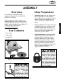
The following is a description of the
components shipped with the SHOP FOX
®
W1708 12" Disc Sander.
Should any parts be missing, examine the
packaging carefully to be sure parts are not
among the packing materials. If any parts are
missing, contact Woodstock International, Inc.
at 360-734-3482 or by e-mail at:
.
1. Disc Sander
2. Miter Gauge
3. Sanding Disc
Figure 3. Disc sander components.
DO NOT connect the
machine to power at this
time. The machine must
remain unplugged
throughout the entire
assembly process. Failure
to do this may result in
serious personal injury.
!
2
3
1
• Workbench Load: Your disc sander has a
small weight load in a small footprint.
Most workbenches are suitable for the disc
sander. Reinforce the workbench if you
question its ability to support the disc
sander.
• Working Clearances: Consider existing and
anticipated needs, size of material to be
processed through each machine, and
space for auxiliary stands, work tables or
other machinery when establishing a
location for your disc sander.
• Lighting and Outlets: Lighting should be
bright enough to eliminate shadows and
prevent eye strain. Electrical circuits
should be dedicated or large enough to
handle amperage requirements. Outlets
should be located near each machine so
power or extension cords are clear of
high-traffic areas. Observe local electrical
codes for proper installation of new
lighting, outlets, or circuits.
ALWAYS make sure that all
entrances to your shop are
locked or that machines
are equipped with safety
lock-out devices to protect
curious children or visitors
from serious injury. Never
allow unsupervised people
in your shop who have not
been fully trained!
Shop Preparation
Box Contents
Overview
ASSEMBLY

ASSEMBLY
-10-
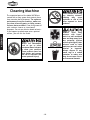
The unpainted parts of the Model W1708 are
coated with a waxy grease that protects them
from corrosion during shipment. For optimum
performance from your machine, make sure
you clean all moving parts or sliding contact
surfaces that are coated. Clean this grease off
with a solvent cleaner or citrus-based
degreaser. Do not use chlorine-based solvents—
if you happen to splash some onto a painted
surface, you will ruin the finish.
NEVER use flammables
such as gas or other
petroleum-based solvents
to clean your machine.
These products have low
flash points and present
the risk of explosion and
severe personal injury!
NEVER smoke while using
any cleaning solvents.
Smoking may cause
explosion or risk of fire
when exposed to these
products!
ALWAYS when using
solvents with fumes,
work in a well ventilated
area and keep away from
any potential ignition
sources (pilot lights). Most
solvents used to clean
machinery are toxic when
inhaled or ingested.
Always dispose of any
waste rags in a sealed
container to make sure
they do not cause fire or
environmental hazards.
Cleaning Machine

ADJUSTMENTS
-11-
The adjustments in this section have been
preset and generally do not need to be
performed when you first receive your disc
sander; however, we suggest that you become
familiar with these adjustments before
operating your disc sander. This will help you
understand the machine and will prepare you
for the types of adjustments that can be made
in troubleshooting and everyday use.
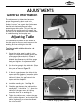
The table must be parallel to the surface of
the disc plate for accuracy and to prevent the
sanding disc from rubbing on the table.
To align the table with the disc plate, do
these steps:
1. Square the miter gauge by placing a try
square or a machinist’s square against the
miter gauge slide as shown in Figure 4.
Loosen the adjustment knob, push the
blade of the square up to the miter gauge
body, and tighten the adjustment knob.
2. Set the miter gauge in the table slot. Place
the square against the miter gauge and the
disc plate as shown in Figure 5.
3. If there is a gap between the blade of the
square and the disc plate, loosen the table
screws shown in Figure 6, and adjust the
table until there is no gap between the
square and the disc plate.
4. Install the sanding disc. See Page 12.
5. Check the gap between the table and the
sanding disc. It should be
1
⁄16". Adjust the
table until the gap is even all the way
across the face of the sanding disc.
6. Tighten the table screws, recheck the gap
and the table alignment, and re-adjust the
table if tightening the screws has caused
the table to shift.
Figure 5. Checking table square.
Figure 4. Squaring the miter gauge.
Figure 6. Aligning table with disc.
Adjusting Table
General Information
ADJUSTMENTS
1
/16"Gap
Table
Screws
Table
Screws

ADJUSTMENTS
-12-
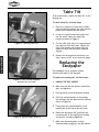
Figure 7. Checking table tilt.
Figure 8. Slide covered sandpaper
between disc and table.
Figure 9. Remove paper backing
To ensure accuracy, adjust the table 90˚ to the
sanding disc.
To check table tilt, do these steps:
1. Place a try square or a machinist’s square
with the base flat against the table and the
blade vertical against the disc plate.
2. If there is a gap between the square and
the disc plate, loosen the table lock
handles as shown in Figure 7.
3. Tilt the table until there is no gap between
the square and the disc plate, tighten the
table lock handles and recheck with the
square to verify that the table remained
aligned.
4. Remove the angle pointer and place it so
that it points to 90˚ on the trunnion gauge.
The sandpaper can be replaced without
removing the table or the dust port.
To replace the sanding disc, do these steps:
1. UNPLUG THE DISC SANDER!
2. Make sure that the disc plate is free of dirt,
dust, and adhesive.
3. Peel back half of the sanding disc backing.
4. Slide the covered portion of the sanding
disc between the disc plate and the table as
shown in Figure 8.
5. Firmly press the exposed portion of the
sanding disc to the top of the disc plate.
6. Rotate the disc plate 180˚, peel back the
remaining half of the sanding disc backing
and press it into place (Figure 9).
7. Make sure the sanding disc is firmly
attached before plugging in the disc sander.
Replacing the
Sandpaper
Table Tilt
Gap

OPERATIONS
-13-
Once the adjustments are complete, the SHOP
FOX
®
W1708 is ready for a test run. The
purpose of a test run is to identify any unusual
noises and vibrations, as well as to confirm
that the machine is performing as intended.
To test run the machine, do these steps:
1. Plug the machine into the power source.
2. Turn the disc sander ON.
3. Keep your hand over the power switch in
case there is a situation that requires you
to quickly turn the power OFF.
Your disc sander should run smoothly with no
strange noises or excessive vibration. UNPLUG
the machine before investigating any unusual
noises.
ALWAYS WEAR safety
glasses during operations.
Serious injury may occur
if this is warning is ig-
nored!
ALWAYS keep loose
clothing and long hair
secured and away from
moving parts.
Test Run
OPERATIONS
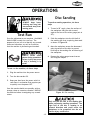
To perform sanding operations, do these
steps:
1. To sand a 90˚ angle, place the surface of
the workpiece that you wish to sand
against the face of the miter gauge (set at
90˚).
2. Slide the workpiece into the left half of
the sanding disc that is spinning downward
as shown in Figure 10.
3. Move the workpiece across the downward
spinning surface of the disc to prevent
build-up on the sanding disc and burning of
the workpiece.
4. Remove the miter gauge to sand curves
and irregular shapes.
Figure 10. Disc sanding.
Disc Sanding
Only use the left half of the sanding disc
when performing sanding operations. The
right half of the disc is rotating in an
upward direction and could cause the
workpiece to be propelled into the air.
Serious injury could occur.

OPERATIONS
-14-
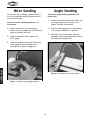
An effective way of making a perfect miter is
to cut the workpiece slightly long and sand it
to the desired angle.
To perform miter sanding operations, do
these steps:
1. Loosen the knob on the miter gauge,
adjust the miter gauge body to the desired
angle and tighten the knob.
2. Hold the workpiece firmly against the
miter gauge.
3. Slide the workpiece along the face of the
miter gauge into the left side of the
sanding disc as shown in Figure 11.
Figure 11. Mitering with gauge angled.
Rotation
To perform angle sanding operations, do
these steps:
1. Loosen the handles securing the table, use
the angle gauge to set the angle, and
tighten the table lock handles.
2. Slide the miter gauge into its slot and use
it to hold your workpiece in position.
3. With light, but firm pressure, push the
workpiece slowly into the downspin side of
the sanding disc (Figure 12).
Figure 12. Mitering with table angled.
Angle SandingMiter Sanding
Rotation

MAINTENANCE
-15-
MAINTENANCE
Lubrication
Since all bearings are sealed and permanently
lubricated, simply leave them alone until they
need to be replaced. Do not lubricate them.
For other items on this machine, an occasional
application of light machine oil is all that is
necessary. Before applying lubricant, wipe the
machine clean.
Your goal is to achieve adequate lubrication.
Too much lubrication will attract dirt and
sawdust. Various parts of your machine could
lose their freedom of movement as a result.
Regular periodic maintenance on your Model
W1708 will ensure its optimum performance.
Make a habit of inspecting your sander each
time you use it. Check for the following
conditions and repair or replace when
necessary.
1. Loose mounting bolts.
2. Worn switch.
3. Worn or damaged cords and plugs.
4. Damaged sanding disc.
5. Any other condition that could hamper the
safe operation of this machine.
General
Table
Tables can be kept rust-free with regular
applications of products like Boeshield
®
T-9. For
long term storage you may want to consider
products like Kleen Bore's Rust Guardit™.
Disconnect power to the
machine when performing
any maintenance, assembly
or adjustments. Failure to do
this may result in serious
personal injury.
!

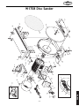
PARTS
-16-
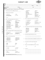
The following pages contain parts diagrams/lists
and a warranty card for your SHOP FOX
®
Model W1708.
If you need parts or help in assembling your
machine, or if you need operational
information, we encourage you to call our
Service Department. Our trained service
technicians will be glad to help you.
If you have comments dealing specifically with
this manual, please write to us using the
address in the General Information. The
specifications, drawings, and photographs
illustrated in this manual represent the Model
W1708 as supplied when the manual was
prepared. However, due to Woodstock
International, Inc.’s policy of continuous
improvement, changes may be made at any
time with no obligation on the part of
Woodstock International, Inc. Whenever
possible, though, we send manual updates to
all owners of a particular tool or machine that
have registered their purchase with our
warranty card. Should you receive one, add the
new information to this manual and keep it for
reference.
We have included some important safety
measures that are essential to this machine’s
operation. While most safety measures are
generally universal, we remind you that each
workshop is different and safety rules should
be considered as they apply to your specific
situation.
We recommend you keep this manual for
complete information regarding
Woodstock International, Inc.’s warranty and
return policy. Should a problem arise, we
recommend that you keep your proof of
purchase with your manual. If you need
additional technical information relating to
this machine, or if you need general assistance
or replacement parts, please contact the
Service Department at 1-360-734-3482 or e-
mail: [email protected]
Additional information sources are necessary to
realize the full potential of this machine. Trade
journals, woodworking magazines, and your
local library are good places to start.
The Model W1708 is specifically designed for
sanding operations. DO NOT MODIFY AND/OR
USE THIS MACHINE FOR ANY OTHER PURPOSE.
MODIFICATIONS OR IMPROPER USE OF THIS
TOOL WILL VOID THE WARRANTY. If you are
confused about any aspect of this machine, DO
NOT use it until all your questions have been
answered.
Closure
As with all power tools, there is danger
associated with the Model W1708. Use the
tool with respect and caution to lessen the
possibility of mechanical damage or
operator injury. If normal safety
precautions are overlooked or ignored,
injury to the operator or others is likely.

PARTS
-17-
W1708 Disc Sander
D
I
S
C
R
O
T
A
T
I
O
N
1
2
3
4
5
5-1
5-2
5-3
5-4
5-5
6
6
7
8
9
10
11
12
12
13
14
15
16
16-1
18
17
19
20
21
19
22
22-3
22-2
22-4
22-5
22-1
23
23
23
23
23
24
26
26
25
27
28
29
30
21
23
26
31
32
32
33
34
35
36
37
38
39
40
34

PARTS
-18-
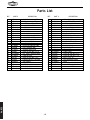
REF PART # DESCRIPTION REF PART # DESCRIPTION
1 X1708001 SHOP FOX LOGO LABEL
2 X1708002 READ MANUAL LABEL
3 X1708003 SAFETY GLASSES LABEL
4 X1708004 MACHINE ID LABEL
5 X1708005 MOTOR 1HP
5-1 X1708005-1 MOTOR FAN
5-2 X1708005-2 FAN COVER
5-3 X1708005-3 WIRING BOX
5-4 XPC100A CAPACITOR 100MFD/250V
5-5 X1708005-5 CAPACITOR COVER
6 XPTLW01M EXT TOOTH WASHER 4MM
7 XPLW01M LOCK WASHER 5MM
8 X1708008 WAVY WASHER 39MM
9 X1708009 ROTATION ARROW LABEL
10 XPW05M FLAT WASHER 4MM
11 X1708011 GROUND INDICATOR
12 XPS09M PHLP HD SCR M5-.8 X 10
13 XPTLW02M EXT TOOTH WASHER 5MM
14 X1708014 CORD & PLUG
15 XPS17M PHLP HD SCR M4-.7 X 6
16 XPSW09 PADDLE SWITCH 110/220V
16-1 XPSW09-1 SWITCH KEY
17 X1708017 RIGHT TRUNNION
18 X1708018 LEFT TRUNNION
19 XPFH06M FLAT HD SCR M6-1 X 20
20 X1708020 WORK TABLE
21 XPN01M HEX NUT M6-1
22 X1708022 COMPLETE MITER GAUGE
22-1 X1708022-1 MITER GAUGE BODY
22-2 X1708022-2 GAUGE SLIDE
22-3 X1708022-3 KNOB BOLT M6-.1 X 22
22-4 X1708022-4 ANGLE POINTER
22-5 XPS19M PHLP HD SCR M5-.8 X 6
23 XPW03M FLAT WASHER 6MM
24 X1708024 REFERENCE LABEL
25 XPS26M PHLP HD SCR M6-1 X 20
26 XPLW03M LOCK WASHER 6MM
27 X1708027 DUST CHUTE COVER
28 X1708028 SPECIAL WASHER
1
⁄4" X 1
1
⁄4"
29 X1708029 SANDING DISC
30 X1708030 RUBBER FOOT
31 X1708031 STOP SCREW
32 X1708032 TABLE LOCK
33 XPS47M PHLP HD SCR M6-1 X 25
34 XPS07M PHLP HD SCR M4-.7 X 8
35 XPK23M KEY 5 X 5 X 25
36 XP6204 BALL BEARING 6204ZZ
37 X1708037 BASE
38 X1708038 80 GRIT SANDING DISC
39 XPSB26M CAP SCREW M6-1 X 12
40 X1708040 TRUNNION REST
Parts List
Page is loading ...
Page is loading ...
Page is loading ...
Page is loading ...
-
 1
1
-
 2
2
-
 3
3
-
 4
4
-
 5
5
-
 6
6
-
 7
7
-
 8
8
-
 9
9
-
 10
10
-
 11
11
-
 12
12
-
 13
13
-
 14
14
-
 15
15
-
 16
16
-
 17
17
-
 18
18
-
 19
19
-
 20
20
-
 21
21
-
 22
22
-
 23
23
-
 24
24


Ask a question and I''ll find the answer in the document
Finding information in a document is now easier with AI
Related papers
-
Woodstock SHOP FOX W1709 User manual
-
-
-
Shop fox SHOP FOX W1815 User manual
-
Woodstock THE SHOP FOX W1500 User manual
-
Woodstock W1688 Owner's manual
-
-
-
-
Shop fox W1687 User manual
Other documents
-
Grizzly G7297 Owner's manual
-
-
Whirlpool RE960PXK User manual
-
-
General International BD7004 User manual
-
Craftex CX Series CX506 Owner's manual
-
-
-
-