2
Rear Trim Accessories
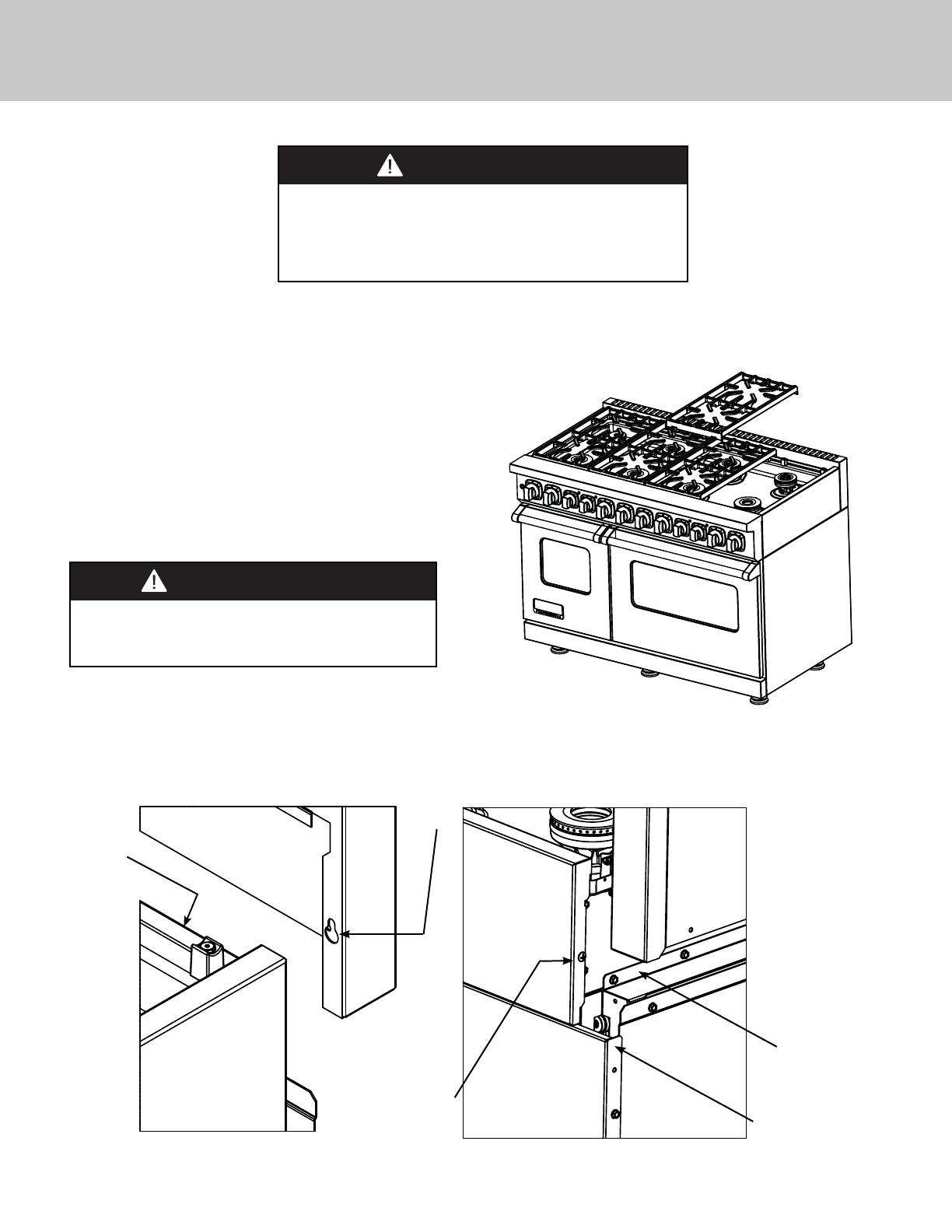
ATTACHING REAR TRIM
(Island Trim, 10” H. Backguard OR 24” H. High Shelf Back Panel)
1. Remove the grate supports in order to locate the rear fl ange
and mounting stud on the unit. Grasp the rear trim on each end
and carefully align the rear trim over the rear fl ange and insert
mounting screw into keyhole opening on the rear trim.
Make sure the rear trim is in front of the sealed burner
box and not behind.
2. Align holes in rear trim with holes in fl ange. Slide
rear trim down until it rest on top of the side panels
ensuring accessory rear wall is outside of unit. Secure
with enclosed #10 x 1/2” (1.3 cm) phillips head
threaded screws. 36” W. ranges/rangetops have (3)
hole locations and 48” W ranges/rangetops have (4).
To reduce the risk of fi re or injury to persons, check to
make sure all packaging has been removed from the
outside and inside parts of the rear trim device before
installing. MAKE SURE ALL CORRUGATED MATERIAL IS
REMOVED FROM INSIDE THE HIGH SHELF.
WARNING
Remove
grates
SIDE VIEW
REAR VIEW
Keyhole
opening
Mounting
screw
Rear fl ange
Side Panel
To reduce the risk of injury, assistance from a
second person is recommended when installing
48” backguards or high shelf backs.
CAUTION


