
K3G11/AUS
K3G11S/AUS
Contents
Installation, 2-7
Positioning and levelling
Electrical connection
Gas connection
Adapting to different types of gas
Technical data
Table of burner and nozzle specifications
Description of the appliance, 8
Overall view
Control panel
Start-up and use,9-11
Using the hob
Using the oven
Electronic timer
Oven cooking advice table
Precautions and tips, 12-13
General safety
Disposal
Respecting and conserving the environment
Care and maintenance, 14-15
Switching the appliance off
Cleaning the appliance
Gas tap maintenance
Replacing the oven light bulb
Assistance
Operating Instructions
COOKER
AUS
AUS
English, 1

2
AUS
! Before operating your new appliance please read
this instruction booklet carefully. It contains
important information concerning the safe installation
and operation of the appliance.
! Please keep these operating instructions for future
reference. Make sure that the instructions are kept
with the appliance if it is sold, given away or moved.
! The appliance must be installed by a qualified
professional according to the instructions provided.
! Any necessary adjustment or maintenance must be
performed after the cooker has been disconnected
from the electricity supply.Positioning
Compliance with standards
This cooktop must be installed in accordance with
the requirements of local gas and electrical
authorities, as well as the latest published versions
of the following standards:
· AS/NZS 5601 Gas Installation code
SAA Wiring Rules.
! It is possible to install the appliance alongside
cupboards whose height does not exceed that of the
hob surface.
! This cooker should be installed directly on! This cooker should be installed directly on
! This cooker should be installed directly on! This cooker should be installed directly on
! This cooker should be installed directly on
the floor. Do not install this cooker on anthe floor. Do not install this cooker on an
the floor. Do not install this cooker on anthe floor. Do not install this cooker on an
the floor. Do not install this cooker on an
artificial base of any kind.artificial base of any kind.
artificial base of any kind.artificial base of any kind.
artificial base of any kind.
! Make sure that the wall in contact with the back of
the appliance is made from a non-flammable, heat-
resistant material (T 90°C).
! Important: Do not install this appliance! Important: Do not install this appliance
! Important: Do not install this appliance! Important: Do not install this appliance
! Important: Do not install this appliance
adjacent to the door or other means ofadjacent to the door or other means of
adjacent to the door or other means ofadjacent to the door or other means of
adjacent to the door or other means of
access to minimise the likelihood of personsaccess to minimise the likelihood of persons
access to minimise the likelihood of personsaccess to minimise the likelihood of persons
access to minimise the likelihood of persons
using the door making contact with pans onusing the door making contact with pans on
using the door making contact with pans onusing the door making contact with pans on
using the door making contact with pans on
the hob surface.the hob surface.
the hob surface.the hob surface.
the hob surface.
Where the total input of all appliances exceeds 3
MJ/h for each cubic metre of the room or enclosure
volume, the space shall be ventilated by one of the
methods detailed below. For the purpose of
assessing the adequacy of ventilation, the space
that cannot be isolated by doors is the ‘volume of a
room’.
Natural ventilation direct from outside
Two permanent openings shall be provided directly
to outside. The openings shall be located to ensure
the distance between the top of the upper opening
and the ceiling of the room or enclosure, and the
distance between the bottom of the lower opening
and the floor of the room or enclosure does not
exceed 5% of the height of the room or enclosure.
The minimum free ventilation area provided by each
opening shall be calculated using the following
formula:
Installation
* Only available in certain models.
A = 3 × T
where
A = the minimum free ventilation area (cm
2
)
T = the total gas consumption of all
appliances (MJ/h)
The minimum vertical dimension of any free
ventilation opening shall be 6 mm.
NOTE 1 When used in this Clause, the termNOTE 1 When used in this Clause, the term
NOTE 1 When used in this Clause, the termNOTE 1 When used in this Clause, the term
NOTE 1 When used in this Clause, the term
‘directly to outside’ means any one of the‘directly to outside’ means any one of the
‘directly to outside’ means any one of the‘directly to outside’ means any one of the
‘directly to outside’ means any one of the
following options, provided that thefollowing options, provided that the
following options, provided that thefollowing options, provided that the
following options, provided that the
ventilation path is unobstructed by buildingventilation path is unobstructed by building
ventilation path is unobstructed by buildingventilation path is unobstructed by building
ventilation path is unobstructed by building
material or insulation:material or insulation:
material or insulation:material or insulation:
material or insulation:
(a) Directly through an outside wall (preferred
option).
(b) Through to an outside wall but offset.
(c) Into a cavity ventilated to outside.
(d) Into an underfloor space ventilated to
outside.
(e) Into a roof space ventilated to outside.
NOTE 2 The two openings may be combinedNOTE 2 The two openings may be combined
NOTE 2 The two openings may be combinedNOTE 2 The two openings may be combined
NOTE 2 The two openings may be combined
provided that the top and bottom of theprovided that the top and bottom of the
provided that the top and bottom of theprovided that the top and bottom of the
provided that the top and bottom of the
opening reach the limits set by this Clause.opening reach the limits set by this Clause.
opening reach the limits set by this Clause.opening reach the limits set by this Clause.
opening reach the limits set by this Clause.
Natural ventilation via adjacent room
Two permanent openings shall be provided in the
room or enclosure. The openings shall be located to
ensure the distance between the top of the upper
opening and the ceiling of the room or enclosure,
and the distance between the bottom of the lower
opening and the floor of the room or enclosure does
not exceed 5% of the height of the room or
enclosure.
The minimum free ventilation area provided by each
opening shall be calculated using the following
formula:
A = 6 × T
where
A = the minimum free ventilation area (cm
2
)
T = the total gas consumption of all
appliances (MJ/h)
These requirements shall apply to all subsequent
rooms until a room is ventilated to outside, in
accordance with the previous section, or the total
input of the appliances does not exceed 3 MJ/h for
each cubic metre of the total volume of the
enclosure and rooms.
The minimum vertical dimension of any free
ventilation opening shall be 6 mm.
NOTE
: The two openings may be combined: The two openings may be combined
: The two openings may be combined: The two openings may be combined
: The two openings may be combined
provided that the top and bottom of the openingprovided that the top and bottom of the opening
provided that the top and bottom of the openingprovided that the top and bottom of the opening
provided that the top and bottom of the opening
reach the limits set by this Clause.reach the limits set by this Clause.
reach the limits set by this Clause.reach the limits set by this Clause.
reach the limits set by this Clause.

AUS
3
To install the appliance correctly:
• Place it in the kitchen, dining room or the bed-sit
(not in the bathroom).
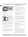
• If the top of the hob is higher than the cupboards,
the appliance must be installed at least 200 mm
away from them.
• If the cooker is installed underneath a wall cabinet,
there must be a minimum distance of 420 mm
between this cabinet and the top of the hob.
This distance should be increased to 700 mm if the
wall cabinets are flammable (
see figure
)
The following minimum clearances to combustible
materials must be observed:
• Minimum clearance from edge of burner to side
wall must be 200 mm.
• Minimum clearance from edge of burner to rear
wall must be 200 mm.
• Do not position blinds behind the cooker or less
than 200 mm away from its sides.
• Range hoods and overhead exhaust fans must be
installed according to manufacturers’ instructions
but in no case shall clearance from hob burners
be less than 600 mm for range hoods and 750
mm for overhead exhaust fans.
If the hood is installed below a wall cabinet, the
latter must be at least 700 mm (millimetres) above
the surface of the hob.
• The cooker is fitted with a safety chain that must
be attached to a screw, secured to the wall
behind the appliance.
! In order to prevent accidental tipping of the
appliance, for example by a child climbing onto the
top oven door, the supplied
safety chain must be
installed.
Ensure the chain is secured
to the rear wall of the oven as
shown, and attach the chain
to a screw secured to the
wall behind the appliance.
Levelling
If it is necessary to level the
appliance, screw the
adjustable feet into the places
provided on each corner of the
base of the cooker (
see
figure
).
The legs* fit into the slots on
the underside of the base of
the cooker.
Installation of the cooker
The appliance can be installed next to furniture units
which are no taller than the top of the cooker hob.
The wall in direct contact with the back panel of the
cooker must be made of non-flammable material.
During operation the back panel of the cooker could
reach a temperature of 50°C above room
temperature. For proper installation of the cooker,
the following precautions must be taken:
a)a)
a)a)
a )The appliance can be placed in a kitchen, dining
room or bedsit, but not in a bathroom.
b)b)
b)b)
b )All furniture around the appliance must be placed
at least 200 mm from the top of the cooker,
should the surface of the appliance be higher than
the worktop of this furniture. Curtains should not
be placed behind the cooker or less than 200 mm
away from the sides of the appliance.
c)c)
c)c)
c )Any hoods must be installed according to the
requirements in the installation manual for the
hoods themselves.
be attached to a screw secured to the wall behind
the appliance.
d)d)
d)d)
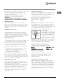
d )If the cooker is installed beneath a wall cabinet,
the latter must be situated at a minimum of 420
mm above the hob. The minimum distance
between the worktop and kitchen units made of
combustible material is 700 mm (Fig. A).
e)e)
e)e)
e )The wall in direct contact with the back panel of
the cooker must be made of non-flammable
materials.
f)f)
f)f)
f ) The cooker is fitted with a safety chain that must
be attached to a screw secured to the wall behind
the appliance.
! Some models can have their gas connection
inverted. It is important to make sure the safety
chain is always situated on the side which
corresponds to the hose holder (Fig. B).

4
AUS
* Only available in certain models.
Gas connection
This appliance is suitable for use with either a
flexible connection or rigid copper connection.
Check The Gas Type
WARNING: Before installation, check that the gas
type (natural gas or
LPG/Propane) of the
cooker is suitable for
the gas type available
to the installation. It is
extremely dangerous to
use the wrong gas type
with any appliance, as
fire or serious injury can
result.
This cooker is supplied
from the factory already set for Natural Gas. To
convert the cooker to LPG (or back to Natural Gas
from LPG), follow the directions later in this section.
Fit regulator supplied for Natural Gas (if applicable)
at rear of appliance, and as close as practicable to
the appliance.
It is recommended that an isolating valve and union
be fitted, to enable simple disconnection for
servicing. These are to be in an accessible location.
.
! Make sure the supply pressure conforms with the
values shown in the table entitled “Caracteristics of
the burners and nozzles”.
When the cooker is installed between cabinets
(recessed), the gas connection must be effected by
an approved flexible hose with bayonet fitting (BS
669 Current Edition). The gas inlet for the cookers is
a threaded G 1/2 gas female fitting.
700 mm
HOT PARTS
Connecting the gas supply
If a flexible hose is used, it should be as short as
possible with a maximum length of 1.5 metres;
• The flexible connection must be approved to
class B or D of AS/NZS1869 as a minimum.
• it should not be bent, kinked or compressed;
• it should not be in contact with the rear wall of the
appliance or in any case with parts which may
reach a temperature of 50°C;
• it should not come into contact with pointed parts
or sharp corners;
• it should not be subject to any pulling or twisting
forces;
• it should be easy to inspect along its entire length
in order to be able to check its condition.
• The supply connection point must be accessible
with the appliance installed.
• The inner diameters of the pipe are as follows:
8 mm for LPG; 13 mm for Natural Gas.
Upon completion of installation, check the gas
circuit, the internal connections and the taps for
leaks using a soapy solution (never a flame). Also
check that the connecting pipe cannot come into
contact with moving parts which could damage or
crush it. Make sure that the natural gas pipe is
adequate for a sufficient supply to the appliance
when all the burners are lit
! Some models can have their gas connection
inverted. It is important to make sure the safety
chain is always situated on the side which
corresponds to the hose holder (Fig. B).
Duplicate Data Plate
Where the data plate is obscured by cabinetry when
the cooker is in the installed position, place a
duplicate data plate on a surface of the cabinetry
adjacent to the cooker.
Electrial Connection
Power supply voltage and frequency: 230-240V a.c.
50/60 Hz.
!!
!!
! The supply cable must be positioned so that it
never reaches at any point a temperature 50°C
higher than the room temperature. The cable must
be routed away from the rear vents. Should you
require it, you may use a longer cable, however, you
must ensure that the cable supplied with the
appliance is replaced by one of the same
specifications in accordance with current standards
and legislation.
HOOD
420
Min.
min.
650
mm. with hood
min.
700
mm. without hood
mm.
600
Min. mm.
420
Min. mm.
Fig. A Fig. B

AUS
5
Your appliance is supplied with a 13 amp fused plug
that can be plugged into a 13 amp socket for
immediate use. Before using the appliance please
read the instructions below.
WARNING - THIS APPLIANCE MUST BE
EARTHED.
THE FOLLOWING OPERATIONS SHOULD BE
CARRIED OUT BY A QUALIFIED ELECTRICIAN.
Replacing the fuse:
When replacing a faulty fuse, a 13 amp ASTA
approved fuse to BS 1362 should always be used,
and the fuse cover re-fitted. If the fuse cover is lost,
the plug must not be used until a replacement is
obtained.
Replacement fuse covers:
If a replacement fuse cover is fitted, it must be of
the correct colour as indicated by the coloured
marking or the colour that is embossed in words on
the base of the plug. Replacements can be obtained
directly from your nearest Service Depot.
Removing the plug:
If your appliance has a non-rewireable moulded plug
and you should wish to remove it to add a cable
extension or to re-route the mains cable through
partitions, units etc., please ensure that either:
• the plug is replaced by a fused 13 amp re-
wireable plug bearing the BSI mark of approval.
or:
• the mains cable is wired directly into a 13 amp
cable outlet, controlled by a switch, (in
compliance with BS 5733) which is accessible
without moving the appliance.
!!
!!
! For appliances with a rating greater than 13 amp
(eg: electric hob, double ovens and freestanding
electric cookers etc.) the mains cable must be wired
into a cooker output point with a rating of 45 amp. In
this case the cable is not supplied.
Disconnecting the cable
Ensure that the means for disconnection of the
power cable is incorporated into the fixed wiring in
accordance with local wiring rules.
(New Zealand statutory warning): The cooker must
be connected to the electricity supply by a cable
fitted with an appropriately rated plug that is
compatible with the socket-outlet fitted to the final
subcircuit in the fixed wiring that is intended to
supply this cooker.
GREEN &
YELLOW
BROWN
BLUE
13 amp fuse
CROSS-BAR
CORD GRIP
Disposing of the plug:
Ensure that before disposing of the plug itself, you
make the pins unusable so that it cannot be
accidentally inserted into a socket. Instructions for
connecting cable to an alternative plug:
!!
!!
! The wires in the mains lead are coloured in
accordance with the following code:
Green & Yellow - Earth
Blue - Neutral
Brown - Live
If the colours of the wires in the mains lead do not
correspond with the coloured markings identifying
the terminals in your plug, proceed as follows:
Connect Green & Yellow wire to terminal marked “
EE
EE
E”
or or coloured Green or Green & Yellow.
Connect Brown wire to terminal marked “
LL
LL
L” or
coloured Red.
Connect Blue wire to terminal
marked “
NN
NN
N” or coloured Black.
If a 13 amp plug (BS 1363) is
used it must be fitted with a
13 amp fuse. A 15 amp plug
must be protected by a 15
amp fuse, either in the plug or
adaptor or at the distribution board. If you are in any
doubt about the electrical supply to your machine,
consult a qualified electrician before use.
How to connect an alternative plug:
The wires in this mains lead are coloured in
accordance with the following code:
BLUEBLUE
BLUEBLUE
BLUE “
NEUTRALNEUTRAL
NEUTRALNEUTRAL
NEUTRAL” (“
NN
NN
N”)
BROWNBROWN
BROWNBROWN
BROWN “
LIVELIVE
LIVELIVE
LIVE” (“
LL
LL
L”)
GREEN AND YELLOWGREEN AND YELLOW
GREEN AND YELLOWGREEN AND YELLOW
GREEN AND YELLOW “
EARTHEARTH
EARTHEARTH
EARTH” (“
EE
EE
E”)
Disposing of the appliance
When disposing of the appliance please remove the
plug by cutting the mains cable as close as
possible to the plug body and dispose of it as
described above.
Checking the connection for leaks
Upon completion of installation, check the gas
circuit, the internal connections and the taps for
leaks using a soapy solution (never a flame). Also
check that the connecting pipe cannot come into
contact with moving parts which could damage or
crush it. Make sure that the natural gas pipe is
adequate for a sufficient supply to the appliance
when all the burners are lit

6
AUS
Adapting to Different Types of Gas
It is possible to adapt the appliance to a type of gas
other than the default type (this is indicated on the
rating label on the cover).
Adapting the hob
Replacing the nozzles for the
hob burners:
1. Remove the hob grids and
slide the burners off their seats.
2. Unscrew the nozzles using a
7 mm socket spanner (
see
figure
), and replace them with
nozzles suited to the new type
of gas (
see Burner and nozzle specifications table
).
3. Replace all the components by following the
above instructions in reverse.
Adjusting the hob burners’ minimum setting:
1. Turn the tap to the minimum position.
2. Remove the knob and adjust the regulatory
screw, which is positioned inside or next to the tap
pin, until the flame is small but steady.
! If the appliance is connected to a liquid gas
supply, the regulatory screw must be fastened as
tightly as possible.
3. While the burner is alight, quickly change the position
of the knob from minimum to maximum and vice versa
several times, checking that the flame is not
extinguished.
! The hob burners do not require primary air adjustment.
! After adjusting the appliance so it may be used
with a different type of gas, replace the old rating
label with a new one that corresponds to the new
type of gas (these labels are available from
Authorised Technical Assistance Centres).
! Should the gas pressure used be different (or vary
slightly) from the recommended pressure, a suitable
pressure regulator must be fitted to the inlet hose in
accordance with current national regulations relating
to “regulators for channelled gas”.
Post Installation Checks
Perform post installation checks and ensure proper
and safe operation before leaving. Test all burners
individually and in combination.
Leak Check
• Ensure all gas control knobs are in the Off
position.
• Ensure the gas supply is switched on.
· Spray a solution of soapy water onto all gas
joints as well as the full length of any flexible hoses.
UNDER NO CIRCUMSTANCES USE A NAKED
FLAME IN CHECKING FOR LEAKS.
If bubbles appear anywhere, turn the gas supply
off, check all connections and retest. If satisfactory
operation cannot be achieved, contact place of
purchase or their appointed agent for service.
Flame check
Turn each burner on, and ensure that the flame is
blue with minimal yellow tipping. If there is
significant yellow tipping, flame lift off or excessive
noise, check pressure and adjust at the regulator if
necessary.
If satisfactory operation cannot be achieved,
contact place of purchase or their appointed agent
for service.
Igniter operation
Check that the igniter for each burner successfully
ignites the gas.
If an igniter fails to work, first remove the plug from
the electrical power outlet, and then check that all
the electrical connections are in place.
If satisfactory operation cannot be achieved,
contact place of purchase or their appointed agent
for service.
Low flame setting
Check the low flame setting for each hob burner to
ensure that the minimum flame will not be
extinguished by air draughts.
• Light the burner.
• Turn the control until it engages in the minimum
position.
• Ensure the flame is stable and will not be
extinguished by air draughts.
To adjust the minimum flame:
Follow the procedure described in the gas
conversion instruction.
DO NOT MODIFY THIS APPLIANCE IN ANY WAY,
OTHER THAN AS DESCRIBED IN THESE
INSTRUCTIONS.

AUS
7
TECHNICAL DATA
Oven dimensions
(HxWxD)
34x39x44 cm
Volume
58 l
Useful
measurements
relating to the
oven
compartment
width 42 cm
depth 44 cm
height 23 cm
Power supply
voltage and
frequency
see data plate
Burners
may be adapted for use with any
type of gas shown on the data
plate, which is located inside the
flap or, after the oven compartment
has been opened, on the left-hand
wall inside the oven.
ENERGY LABEL
Directive 2002/40/EC on the label
of electric ovens. Standard EN
50304
Declared energy consumption for
Natural convection Class – heating
mode:
Static
EC Directives: 2006/95/EEC dated
12/12/06 (Low Voltage) and
subsequent amendments -
89/336/EEC dated 03/05/89
(Electromagnetic Compatibility) and
subsequent amendments -
90/369/EEC dated 29/06/90 (Gas)
and subsequent amendments -
93/68/EEC dated 22/07/93 and
subsequent amendments -
2002/96/EC.
S
S
R
A
Technical Specification
Gas Consumption
Natural Gas (1.0 kPa) ULPG (2.75 kPa)
Injector
Diameter
Gas Input
Injector
Diameter
Gas Input
Auxiliary Burner 0.85 mm 3.7 MJ/hr 0.50 mm 3.1 MJ/hr
Semi Rapid Burners (x2) 1.10 mm 6.0 MJ/hr 0.64 mm 5.5 MJ/hr
Rapid Burner 1.29 mm 8.2 MJ/hr
0.80 mm 8.5 MJ/hr
Total 23.9 MJ/hr 22.6 MJ/hr
Connections
Gas Inlet fitting 1/2” BSP (male) thread
Location of gas inlets at rear of cooker
222 mm from top of cooker
20 mm from left edge of cooker
Alternative inlet 20mm from right edge of cooker.
K3G11/AUS
K3G11S/AUS

8
AUS
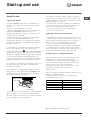
Hob grid
Control panel
GRILL
DRIPPING PAN
GUIDE RAILS
for the sliding racks
position 3
position 2
position 1
Gas burner
Containment surface
for spills
Adjustable foot
Adjustable foot
position 5
position 4
Overall View
Control Panel
**
**
*
Only available in certain models.
TIMER
knob*
THERMOSTAT
knob
THERMOSTAT
indicator light
Hob BURNER
control knobs
SELECTOR
Knob
GAS BURNER
ignition button*
Description of the appliance

AUS
9
Using The Hob
Lighting the burners
For each BURNER knob there is a complete ring
showing the strength of the flame for the relevant
burner.
To light one of the burners on the hob:
1. Bring a flame or gas lighter close to the burner.
2. Press the BURNER knob and turn it in an
anticlockwise direction so that it is pointing to the
maximum flame setting E.
3. Adjust the intensity of the flame to the desired
level by turning the BURNER knob in an
anticlockwise direction. This may be the minimum
setting C, the maximum setting E or any position in
between the two.
If the appliance is fitted with an electronic lighting
device* (
see figure
), press the ignition button,
marked with the symbol
11
11
1, then hold the BURNER
knob down and turn it in an anticlockwise direction,
towards the maximum flame setting, until the burner
is lit. The burner may be extinguished when the
knob is released. If this occurs, repeat the operation,
holding the knob down for a longer period of time.
! If the flame is accidentally extinguished, switch off
the burner and wait for at least 1 minute before
attempting to relight it.
If the appliance is equipped with a flame failure
safety device*, press and hold the BURNER knob
for approximately 2-7 seconds to keep the flame
alight and to activate the device.
Check that the gas has been lit. If the burner fails to
ignite try again. If the burner fails to ignite after 3
attempts, wait a few minutes for the gas to disperse
before making any further attempts.
.
Start-up and use
If the burner still fails to ignite, a match or lighting
device can be used, but care must be taken. If the
problem persists, contact place of purchase or their
appointed agent for service.
If the flame has excessive yellowing, or appears to
lift off the burner ports, or makes a loud noise, turn
the burner off and call your service agent.
To switch the burner off, turn the knob until it
reaches the stop position •
Lighting the burners for the first time
If the appliance is being used for the first time, or if
it has not been used for a long period of time, it may
be necessary to purge the gas lines of excess air
before you can successfully light the burners.
To do this, turn each burner to High for 10-15
seconds and press the ignition button several times.
If the burner does not light, repeat this procedure
twice more. Wait 1-2 minutes for any gas build up to
disperse before allowing any further gas flow.
Practical advice on using the burners
For the burners to work in the most efficient way
possible and to save on the amount of gas
consumed, it is recommended that only pans that
have a lid and a flat base are used. They should
also be suited to the size of the burner.
To identify the type of burner, please refer to the
diagrams contained in the “Technical
specifications”.
Do not use pans which are unstable or which have a
warped or damaged base.
Ensure the pot sits securely on the trivet and is
centred above the burner.
HOB GAS BURNER
SAFETY DEVICE
ELECTRONIC
LIGHTING DEVICE
Burner ø Cookware diameter (cm)
Fast (R) 24 - 26
Semi Fast (S) 16 - 20
Auxiliary (A) 10 - 14
**
**
*
Only available in certain models.

10
AUS
Using The Oven
! The first time you use your appliance, heat the
empty oven with its door closed at its maximum
temperature for at least half an hour. Ensure that the
room is well ventilated before switching the oven off
and opening the oven door. The appliance may emit
a slightly unpleasant odour caused by protective
substances used during the manufacturing process
burning away.
! Before operating the product, remove all plastic
film from the sides of the appliance.
1. Select the desired cooking mode by turning the
SELECTOR knob.
2. Select the recommended temperature for the
cooking mode or the desired temperature by turning
the THERMOSTAT knob.
A list detailing cooking modes and suggested
cooking temperatures can be found in the relevant
table (
see Oven cooking advice table
).
Note: at the minimum thermostat settingNote: at the minimum thermostat setting
Note: at the minimum thermostat settingNote: at the minimum thermostat setting
Note: at the minimum thermostat setting
(130°C) the thermostat can underestimate(130°C) the thermostat can underestimate
(130°C) the thermostat can underestimate(130°C) the thermostat can underestimate
(130°C) the thermostat can underestimate
temperatures by up to 17°C.temperatures by up to 17°C.
temperatures by up to 17°C.temperatures by up to 17°C.
temperatures by up to 17°C.
During cooking it is always possible to:
• Change the cooking mode by turning the
SELECTOR knob.
• Change the temperature by turning the
THERMOSTAT knob.
• Set the total cooking time and the cooking end
time (
see below
).
• Stop cooking by turning the SELECTOR knob to
the “0” position.
! Never put objects directly on the bottom of the
oven; this will avoid the enamel coating being
damaged. Only use position 1 in the oven when
cooking with the rotisserie spit.
! Always place cookware on the rack(s) provided.
! When inserting the shelves onto the guide! When inserting the shelves onto the guide
! When inserting the shelves onto the guide! When inserting the shelves onto the guide
! When inserting the shelves onto the guide
rails, ensure the raised sections is towardsrails, ensure the raised sections is towards
rails, ensure the raised sections is towardsrails, ensure the raised sections is towards
rails, ensure the raised sections is towards
the rear of the oven. This prevents food fromthe rear of the oven. This prevents food from
the rear of the oven. This prevents food fromthe rear of the oven. This prevents food from
the rear of the oven. This prevents food from
falling off the back of the tray.falling off the back of the tray.
falling off the back of the tray.falling off the back of the tray.
falling off the back of the tray.
THERMOSTAT indicator light
When this is illuminated, the oven is generating
heat. It switches off when the inside of the oven
reaches the selected temperature. At this point the
light illuminates and switches off alternately,
indicating that the thermostat is working and is
maintaining the temperature at a constant level.
Oven light
This is switched on by turning the SELECTOR knob
to any position other than “0”. It remains lit as long
as the oven is operating. By selecting
88
88
8 with the
knob, the light is switched on without any of the
heating elements being activated.
Cooking Modes
! A temperature value can be set for all cooking
modes between 50°C and MAX, except for the
GRILL programme, for which only the MAX power
level is recommended.
STATIC OVEN mode
Both the top and bottom heating elements will come
on. When using this traditional cooking mode, it is
best to use one cooking rack only. if more than one
rack is used, the heat will be distributed unevenly.
OVEN BOVEN B
OVEN BOVEN B
OVEN B
OTTOMOTTOM
OTTOMOTTOM
OTTOM mode
The lower heating element is activated. This position
is recommended for perfecting the cooking of
dishes (in baking trays) which are already cooked on
the surface but require further cooking in the centre,
or for desserts with a covering of fruit or jam, which
only require moderate colouring on the surface. It
should be noted that this function does not allow the
maximum temperature to be reached inside the oven
(250°C) and it is therefore not recommended that
foods are cooked using only this setting, unless you
are baking cakes (which should be baked at a
temperature of 180°C or lower).
GRILL mode
The top heating element is activated. The extremely
high and direct temperature of the grill makes it
possible to brown the surface of meats and roasts
while locking in the juices to keep them tender.
DOUBLE GRILL mode
The top heating element and the rotisserie spit will
be activated. The grill is also highly recommended
for dishes that require a high surface temperature:
beef steaks, veal, rib steak, fillets, hamburgers
etc...
! The GRILL and DOUBLE GRILL cooking modes must
be performed with the oven door shut.

AUS
11
Timer*
To activate the Timer proceed as follows:
1. Turn the TIMER knob in a clockwise direction 4
for almost one complete revolution to set the buzzer.
2. Turn the TIMER knob in an anticlockwise direction
5 to set the desired length of time.
Lower compartment*
There is a compartment
underneath the oven
that may be used to
store oven accessories
or deep dishes. To open
the door pull it
downwards (
see
figure
).
! The internal surfaces of the compartment (where
present) may become hot.
! Do not place flammable materials in the lower oven
compartment.
! !
! !
! WARNING
- -
- -
- Accesible parts may become
hot when the grill is in use. Children should
be kept away.
Practical Cooking Advice
! In the GRILL cooking mode, place the dripping
pan in position 1 to collect cooking residues (fat
and/or grease).
GRILL
• Insert the rack in position 3 or 4. Place the food in
the centre of the rack.
• We recommend that the power level is set to
maximum. The top heating element is regulated
by a thermostat and may not always operate
constantly.
PIZZA
• Use a light aluminium pizza pan. Place it on the
rack provided.
For a crispy crust, do not use the dripping pan as
it prevents the crust from forming by extending
the total cooking time.
• If the pizza has a lot of toppings, we recommend
adding the mozzarella cheese on top of the pizza
halfway through the cooking process.
**
**
*
Only available in certain models.
Oven cooking advice table
Cooking
modes
Foods Weight
(in kg)
Rack
position
Preheating time
(min)
Recommended
Temperature
(°C)
Cooking
time
(minutes)
Static
Lasagne
Cannelloni
Baked pasta
Veal
Chicken
Duck
Rabbit
Pork
Lamb
Mackerel
Mackerel
Trout baked in foil
Neapolitan-style pizza
Biscuits and small cakes
Sweet unleavened flans and desserts
Savoury pies
Leavened cakes
Fruit cakes
2.5
2.5
2.0
1.7
1.5
1.8
2
2.1
1.8
1.1
1.5
1
1
0.5
1.1
1
0.5
1
2
3
3
2
3
3
3
3
3
2
2
2
2
3
3
3
3
3
5
5
5
10
10
10
10
10
10
5
5
5
15
10
10
10
10
10
200
200
200
180
200
180
180
180
180
180
180
180
220
180
180
180
160
170
45-50
30-35
30-35
60-70
80-90
90-100
70-80
70-80
70-80
30-40
30-35
25-30
15-20
10-15
25-30
30-35
25-30
25-30
Oven bottom Perfecting cooking
Grill
Sole and cuttlefish
Squid and prawn kebabs
Cod fillet
Grilled vegetables
1
1
1
1
4
4
4
3/4
5
5
5
5
Max
Max
Max
Max
8
4
10
8-10
Double Grill
Veal steak
Chops
Hamburgers
Mackerel
Toast
1
1.5
1
1
4 pcs
4
4
3
4
4
5
5
5
5
5
Max
Max
Max
Max
Max
15-20
20
7
15-20
5

12
AUS
Precautions and tips
! This appliance has been designed and
manufactured in compliance with international safety
standards.The following warnings are provided for
safety reasons and must be read carefully.
General Appliance Warnings
• Read the recommendations in this instruction
booklet carefully, as they give important advice
regarding safe installation, use and maintenance.
Keep this booklet in a safe place for further
reference when required.
• This appliance is not suitable for marine craft,
caravans or recreational vehicles.
• This appliance has been designed for private,
nonprofessional use in normal dwellings.
• This appliance is not intended for use by persons
(including children) with reduced physical,
sensory or mental capabilities, or lack of
experience and knowledge, unless they have
been given supervision or instruction concerning
the use of the appliance by a person responsible
for their safety.
• Children should be supervised to ensure they do
not play with this appliance.
• Always make sure the knobs are in the OFF
position when the appliance is not in use.
• The openings used for ventilation and dispersion
of heat must never be covered.
• During operation, the oven glass door, adjacent
parts of the appliance and the internal sections of
the appliance become hot. Care should be taken
to avoid touching any of these parts.
• Accessible parts may become hot during use. To
avoid burns young children should be kept away.
• The appliance was designed for domestic use
inside the home and is not intended for
commercial or industrial use.
• Make sure that power supply cables of other
electrical appliances do not come into contact
with hot parts of this appliance.
• Always use oven gloves when placing or
removing cookware into or out of the oven.
• Do not use flammable liquids (alcohol, petrol,
etc...) near the appliance while it is in use.
• Do not place flammable material in the lower
storage compartment or in the oven itself. If the
appliance is accidentally switched on, these
materials could catch fire. Care must be taken
when using the bottom storage drawer, as the
internal bottom surface of this drawer can get very
hot.
Installation Warnings
• The appliance must not be installed outdoors,
even in covered areas. It is extremely dangerous
to leave the appliance exposed to weather.
• The appliance must be installed by a qualified
person in compliance with the instructions
provided, and should be used for the purpose for
which it was designed. Any other purpose (for
example, heating the room) constitutes improper
use of the cooker and is dangerous. The
manufacturer shall not be held responsible for any
harm caused to persons or animals or for any
damage to property resulting from incorrect
installation, or caused as a result of improper,
incorrect or unreasonable use of the appliance.
• The electrical safety of this appliance is only
guaranteed when it has been correctly connected
to an efficient earthed electricity supply in
compliance with current electrical safety
regulations. This is a fundamental safety
requirement that must be checked and, if there is
any doubt, you should ask a professionally
qualified technician to carry out a thorough check
of the supply system. The manufacturer may not
be held responsible for any damage caused by a
mains supply that has not been earthed correctly.
• Before connecting the appliance, make sure its
rating (which can be found on the appliance itself
and/or on the packaging) corresponds to the gas
and electrical power supply.
• Make sure that the mains supply and the
electrical sockets can withstand the maximum
power of the appliance, which is indicated on the
serial number plate. If there is any doubt, contact
a professionally qualified technician.
• Some parts are covered with a removable scratch-
proof film. Before using the appliance the film
should be removed and the underlying part
cleaned with a cloth and a non-abrasive
household cleaning product. When switching on
for the first time, it is advisable to heat the empty
oven at maximum temperature for about 30
minutes to eliminate any residue from
manufacture.
• In order to prevent accidental tipping of the
appliance, for example by a child climbing onto
the open oven door, the supplied safety chain
must be installed. Refer to the installation section
of this manual for details.
• Do not lean or rest heavy objects on the open
door.

AUS
13
Safety With The Cooktop
• Never leave cooking food unattended. Do not
allow the liquid to boil dry
• Do not use asbestos mats or heat diffusers, as
these trap the heat and can cause damage to the
cooktop from overheating.
• Don’t wear loose clothing while cooking, as
garments may catch utensil handles or catch fire.
• Use dry utensil holders. Wet pot holders can build
up steam. Do not use towels or other large pieces
of cloth to pick up cooking utensils, as these may
touch the heating element and catch fire.
• Do not allow pot handles to overhang other
burners that are in use, as this will cause
scorching of the handle, and potential handling
burns.
• Always make sure that pan handles are turned
towards the centre of the hob in order to avoid
accidental burns.
• Always make sure the knobs are in the OFF
position when the appliance is not in use.
Maintenance Warnings
• DO NOT MODIFY THIS APPLIANCE.
• When you have removed the packing, check that
the appliance is not damaged. If you have any
doubts, do not use the appliance and contact
your nearest Ariston Service Centre.
• There are no user serviceable parts within this
appliance. For any service, contact the place of
purchase or the nominated service agent. Do not
attempt repairs yourself.
• Do not touch hot surfaces. Allow hob to cool
before wiping spillage.
• Do not attempt to replace the power supply cable
yourself. If the cable is damaged or needs
replacing, contact a technical assistance centre
that has been authorised by the manufacturer.
• Always disconnect the appliance from the mains
supply (either by unplugging it or by shutting off
the switch) before cleaning it or carrying out any
maintenance work. When unplugging the
appliance, always pull the plug from the mains
socket; do not pull on the cable.
• Never perform any cleaning or maintenance work
without having disconnected the appliance from
the electricity mains.
• Before disposing of the appliance, make it
unusable by unplugging it and cutting off the
power supply cable. It is also advisable to
remove any potentially hazardous parts,
especially with regard to children who may use
the old appliance as a toy.
• Periodically check the condition of the gas
connection pipe and have it replaced by a
qualified technician as soon as it shows any signs
of wear or damage.
Gas And Electrical Safety
• If you are using small domestic appliances near
the hob, ensure that their power supply cables do
not come into contact with the hot parts of the
surface.
• DO NOT SPRAY AEROSOLS IN THE VICINITY OF
THIS APPLIANCE WHILE IT IS IN OPERATION.
• DO NOT USE OR STORE FLAMMABLE
MATERIALS IN THE STORAGE COMPARTMENT
OR NEAR THIS APPLIANCE.
Gas appliances require a regular air supply to
maintain efficient operation. Always ensure that the
kitchen is adequately ventilated whilst the appliance
is in use.
Respecting And Conserving
The Environment
• You can help to reduce the peak load of the
electricity supply network companies by using the
oven in the hours between late afternoon and the
early hours of the morning.
• Always keep the oven door closed when using the
GRILL and DOUBLE GRILL modes. This will
achieve better results while saving energy
(approximately 10%).
• Check the door seals regularly and wipe them clean
to ensure they are free of debris so that they adhere
properly to the door, thus avoiding heat dispersion.

14
AUS
Switching The Appliance Off
Disconnect your appliance from the electricity supply
before carrying out any work on it.
DO NOT TOUCH HOT SURFACES. ALLOW
COOKTOP AND ALL OVEN SURFACES TO COOL
COMPLETELY BEFORE CLEANING.
Cleaning The Appliance
! Do not use abrasive or corrosive detergents such as
stain removers, anti-rust products, powder detergents or
sponges with abrasive surfaces: these may scratch the
surface beyond repair.
! Never use steam cleaners or pressure cleaners on the
appliance.
• It is usually sufficient simply to wash the hob using a
damp sponge and dry it with absorbent kitchen roll.
• The stainless steel or enamel-coated external parts and
the rubber seals may be cleaned using a sponge that
has been soaked in lukewarm water and neutral soap.
Use specialised products for the removal of stubborn
stains. After cleaning, rinse well and dry thoroughly. Do
not use abrasive powders or corrosive substances.
• The hob grids, burner caps, flame spreader rings and
burners may be removed to make cleaning easier;
wash them in hot water and non-abrasive detergent,
making sure all burnt-on residue is removed before
drying them thoroughly.
• For hobs with electronic ignition, the terminal part of the
electronic lighting devices should be cleaned
frequently and the gas outlet holes should be checked
for blockages.
• The inside of the oven should ideally be cleaned after
each use, while it is still lukewarm. Use hot water and
detergent, then rinse well and dry with a soft cloth. Do
not use abrasive products.
•
Clean the glass part of the oven door using a sponge
and a non-abrasive cleaning product, then dry
thoroughly with a soft cloth.
• Do not use harsh abrasive cleaners or materials,
or metal scrapers to clean the oven door glass
since these can scratch the surface, which may
result in shattering of the glass.
• The accessories can be washed like everyday
crockery, and are even dishwasher safe.
• Stainless steel can be marked by hard water that has
been left on the surface for a long time, or by
aggressive detergents containing phosphorus. After
cleaning, rinse well and dry thoroughly. Any remaining
drops of water should also be dried.
Inspecting The Oven Seals
Check the door seals around the oven regularly. If the
seals are damaged, please contact your nearest
Authorised After-sales Service Centre. We recommend
that the oven is not used until the seals have been
replaced.
Gas Tap Maintenance
Over time, the taps may become jammed or difficult to
turn. If this occurs, the tap must be replaced.
!This procedure must be performed by a qualified
technician authorised by the manufacturer.
Replacing The Oven Light Bulb
1. After disconnecting the oven
from the electricity mains, remove
the glass lid covering the lamp
socket (
see figure
).
2. Remove the light bulb and
replace it with a similar one:
voltage 230 V, wattage 25 W, cap
E 14.
3. Replace the lid and reconnect the oven to the electricity
supply.
Cleaning The Cooktop
• Always wipe spills up when they occur. Do not
leave spills to dry onto the surface of the hob.
• It is usually enough to wash the hob with a damp
sponge and dry it with absorbent kitchen roll.
• NOTE: Do not put hot components in cold water.
The sudden temperature shock could cause the
component to crack.
• Do not use abrasive or corrosive detergents such
as stain removers, anti-rust products, powder
detergents or sponges with abrasive surfaces:
these may scratch the surface beyond repair.
Care and maintenance

AUS
15
Burners
• Wait for the cooktop to cool completely. Remove
the burner cap and check the gas outlet holes for
blockages. Clean with a soft bristle brush and
warm soapy water.
• The removable parts of the burners should be
washed frequently with warm water and soap and
any burnt-on substances removed.
• Dry the burner parts thoroughly before replacing.
Ignitors
• The terminal part of the electronic instant lighting
devices and flame failure probes should be
cleaned frequently.
Enamelled Parts (trivets)
• Never use abrasives, scouring pads or sharp
objects. This will cause irreparable damage to the
enamel.
• Clean the enamelled parts with soapy water when
cold and wipe off with a clean, dry cloth. The
enamel could dull if cleaned while still hot.
Stainless Steel and Chromed Parts
• Stainless steel can be marked by hard water that
has been left on the surface for a long time, or by
aggressive detergents containing phosphorus.
After cleaning, rinse and dry any remaining drops
of water.
• Use commercial products designed for cleaning
stainless steel and chromed steel, and follow the
maker’s instructions. Care should be taken when
cleaning around graphics.
• Never use steam cleaners or pressure cleaners on
the appliance.
Grill Plate
• We recommend that the grill plate be cleaned
while it is still hot, using the knobs provided to
move it from the cooking rack to the sink. Wash
the grill plate with hot water and non-abrasive
detergent.
Assistance
Please have the following information to hand:
• The appliance model (Mod.).
• The serial number (S/N).
This information can be found on the data plate located on
the appliance and/or on the packaging.
To keep your cooker running smoothly, we
recommend that you have your cooker serviced
every 5 years by an authorised service agent.

16
AUS
02/2010 - 195074971.00
XEROX FABRIANO
INDESIT
PRIORITY SERVICE
If you are not completely satisfied with your appliance
or require service call:
Australia
Phone: 1300 815 589
AUSTRALIA
ARISIT PTY LIMITED
40-44 Mark Anthony Drive, Dandenong South,
VIC 3175, Australia
Fax: Service & Sales (03) 9768 0838
Email: consumer[email protected]
GENUINE ACCESSORIES
& SPARE PARTS
A wide range of genuine
accessories are available for your appliance call:
Australia
Phone: (03) 9768 0888
-
 1
1
-
 2
2
-
 3
3
-
 4
4
-
 5
5
-
 6
6
-
 7
7
-
 8
8
-
 9
9
-
 10
10
-
 11
11
-
 12
12
-
 13
13
-
 14
14
-
 15
15
-
 16
16


Ask a question and I''ll find the answer in the document
Finding information in a document is now easier with AI
Related papers
-
Indesit K3G11(W)/AUS User guide
-
Whirlpool I6T52(W)/AUS User guide
-
-
-
-
Indesit PC 640 T X AUS.1 User guide
-
-
-
-
Other documents
-
Whirlpool WS6TMC2CXAUS User manual
-
-
Ariston PC 640 T X AUS User manual
-
DeLonghi BQ 58 Datasheet
-
-
-
-
-
Scholtes TG 755 P GH Operating Instructions Manual
-