Page is loading ...

(800) 235-3423 • (864) 433-0333 • AFLglobal.com1.24.20
ASCEND
™
SPLICE CASSETTE
INSTALLATION INSTRUCTIONS
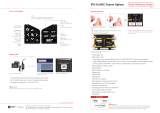
MATERIALS
INCOMING FIBER PREPARATION (INSIDE PLANT CABLE)
This document provides installation instructions for the ASCEND Splice Cassette.
1. Cassette Housing with Pigtails
2. Clear Plastic Cover
3. Splice Holder Kit
4. Cable Mounting Clip
5. Splice Sleeve Kit
1
1
2
4
3
5
Required Tools: Fusion Splicer, Ring Cutter, Sheers, Tape Measure
MAIN TRUNK
12-FIBER SUB UNIT
CABLE MOUNTING CLIP
46"
32" 14"
250 µm
1. Measure and ring cut 46" from the end of the main cable trunk.
2. Remove 4-6" of cable sheath to expose the rip cord and subunits.
3. Split the cable sheath by pulling the rip cord towards the end of the cable. Remove the split cable sheath.
4. Remove any loose aramid yarn and rip cords.
5. Label each sub-unit as necessary.
6. With the subunits exposed, measure and ring cut 14” from the end of each subunit to expose the ber.
7. Ensure sub-unit tubing is located accordingly. Sub-unit tubing should extend just beyond the splice chamber wall when
entering cassette (Figure 1).
Figure 1

(800) 235-3423 • (864) 433-0333 • AFLglobal.com INS-01006
INCOMING FIBER PREPARATION (OUTSIDE PLANT CABLE)
MAIN TRUNK
FURCATION TUBING
CABLE MOUNTING CLIP
46"
30" 14"
250 µm
1. Cut supplied furcation tubing to 30" before starting the cable preparation process.
2. Measure and ring cut 46" from the end of the main cable trunk. Remove cable jacket.
3. Measure and mark the buffer tubes 2.5" in front of the ring cut.
4. At the 2.5" mark, score and remove the buffer tube segment. Thoroughly clean the 250 μm ber.
5. Slide each group of 250 μm bers through a furcation tube. The furcation and buffer tube should overlap 0.5".
6. Secure furcation tubing to buffer tube with tape or heat shrink.
7. Label each sub-unit as necessary.
8. Ensure furcation tubing is located accordingly. Furcation tubing should extend just beyond the splice chamber
wall when entering cassette (Figure 2).
LOOSE TUBE
TAPE
2.5"
Figure 2
2

(800) 235-3423 • (864) 433-0333 • AFLglobal.com1.24.20
INCOMING FIBER PREPARATION (eABF
®
AIR-BLOWN FIBER)
MAIN TRUNK
CABLE MOUNTING CLIP
14"
250 µm
1. Measure and mark the eABF 14” from the end of the main cable trunk
2. Using wire stripping pliers score and remove the 14” eABF outer jacket segment
3. Cut the aramid yarn back to the cable sheath cut.
FIBER SPLICING
1. Orient the splice cradle for single or mass splicing (Figures 3 and 4, respectively).
2. Organize the prepared incoming ber and pigtails on a suitable work surface.
3. Measure and mark the pigtails 27” from the connector boot and cut the bers (Figure 5 and 6).
4. Slide the splice sleeves onto the pigtails (Figure 7).
Note: single splice sleeves are 28 mm sleeves. Set Splicer heater accordingly.
5. Prepare the matched incoming and pigtail bers for splicing: Strip, Clean, and Cleave. Secure the prepared bers in the splicer.
6. Splice Fibers. Position splice sleeve over exposed ber and use heater to shrink the sleeve. Repeat for all matched incoming and pigtail ber pairs (Figure 8).
7. Place each splice sleeve into the splice cradle (Figure 9).
8. Attach the splice holder assembly cover once all the splice sleeves have been inserted (Figure 10).
Figure 3 Figure 4 Figure 5 Figure 6
Figure 7 Figure 8 Figure 9 Figure 10
3

(800) 235-3423 • (864) 433-0333 • AFLglobal.com INS-010064
SPLICE CASSETTE ASSEMBLY
1. Route the pigtail bers inside of the splice cassette. Create two-and-a-half (2.5) loops around the bottom of cassette by rotating the cassette counter clockwise
(Figure 11).
2. Mount the splice sleeve holder assembly on the cassette base (Figure 12).
3. Route the incoming bers into the cassette on top of the pigtail bers. Wrap the ber one (1) time around the base (Figure 13).
4. Place the cable mounting clip onto the incoming ber in the correct opening – 3 mm or 900 μm (Figure 14).
5. Mount the incoming ber into the module using the mounting clip into the center slot. Cable jacket should extend just beyond the chamber wall (Figure 15).
6. Place the plastic cover over the module and slide it forward to lock it into place (Figure 16).
To install the cassette into an ASCEND housing, follow the procedure outlined in the ASCEND Cassette Installation Instructions.
Note: A separate cable mounting bracket kit should be used to secure the cable to the side of the housing.
Figure 11 Figure 12 Figure 13 Figure 14
Figure 15 Figure 16
3 mm
900 μm
/