Page is loading ...

Read through carefully and understand these instructions before use.
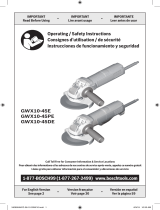
Disc Grinder
Handling instructions
G10SQ • G 12SQ • G 13SQ
G12SQ
10.2.16, 10:202

1
15° – 30°
AB
1 Wernch
2 Wheel nut
3 Depressed center wheel
4 Wheel washer
5 Wheel guard
6 Spindle
7 Push button
8 Off lock lever
9 Switch lever
0 Tail cover
A
On lock button
1
2
3
4
5
6
7
(a)
8
9
0
A
B
(b)
A
C
1
3
2
10.2.8, 14:101

2
10.2.16, 10:252

3
01Chs_G10SQ_ChS.p65 12.7.26, 10:263

4
×
×
×
×
01Chs_G10SQ_ChS.p65 12.7.26, 14:284

5
䡬
䡬
䡬
01Chs_G10SQ_ChS.p65 12.7.20, 9:595

6
䡬
䡬
䡬
䡬
䡬
䡬
䡬
01Chs_G10SQ_ChS.p65 12.7.20, 9:596

7
GENERAL SAFETY RULES
WARNING!
Read all instructions
Failure to follow all instructions listed below may result in
electric shock, fire and/or serious injury.
The term “power tool” in all of the warnings listed below
refers to your mains operated (corded) power tool or battery
operated (cordless) power tool.
SAVE THESE INSTRUCTIONS
1) Work area
a) Keep work area clean and well lit.
Cluttered and dark areas invite accidents.
b) Do not operate power tools in explosive
atmospheres, such as in the presence of flammable
liquids, gases or dust.
Power tools create sparks which may ignite the
dust of fumes.
c) Keep children and bystanders away while operating
a power tool.
Distractions can cause you to lose control.
2) Electrical safety
a) Power tool plugs must match the outlet.
Never modify the plug in any way.
Do not use any adapter plugs with earthed
(grounded) power tools.
Unmodified plugs and matching outlets will reduce
risk of electric shock.
b) Avoid body contact with earthed or grounded
surfaces such as pipes, radiators, ranges and
refrigerators.
There is an increased risk of electric shock if your
body is earthed or grounded.
c) Do not expose power tools to rain or wet
conditions.
Water entering a power tool will increase the risk
of electric shock.
d) Do not abuse the cord. Never use the cord for
carrying, pulling or unplugging the power tool.
Keep cord away from heat, oil, sharp edges or
moving parts.
Damaged or entangled cords increase the risk of
electric shock.
e) When operating a power tool outdoors, use an
extension cord suitable for outdoor use.
Use of a cord suitable for outdoor use reduces
the risk of electric shock.
3) Personal safety
a) Stay alert, watch what you are doing and use
common sense when operating a power tool.
Do not use a power tool while you are tired or
under the influence of drugs, alcohol or medication.
A moment of inattention while operating power
tools may result in serious personal injury.
b) Use safety equipment. Always wear eye protection.
Safety equipment such as dust mask, non-skid
safety shoes, hard hat, or hearing protection used
for appropriate conditions will reduce personal
injuries.
c) Avoid accidental starting. Ensure the switch is in
the off position before plugging in.
Carrying power tools with your finger on the
switch or plugging in power tools that have the
switch on invites accidents.
d) Remove any adjusting key or wrench before
turning the power tool on.
A wrench or a key left attached to a rotating part
of the power tool may result in personal injury.
e) Do not overreach. Keep proper footing and balance
at all times.
This enables better control of the power tool in
unexpected situations.
f) Dress properly. Do not wear loose clothing or
jewellery. Keep your hair, clothing and gloves
away from moving parts.
Loose clothes, jewellery or long hair can be caught
in moving parts.
g) If devices are provided for the connection of dust
extraction and collection facilities, ensure these
are connected and properly used.
Use of these devices can reduce dust related hazards.
4) Power tool use and care
a) Do not force the power tool. Use the correct
power tool for your application.
The correct power tool will do the job better and
safer at the rate for which it was designed.
b) Do not use the power tool if the switch does not
turn it on and off.
Any power tool that cannot be controlled with the
switch is dangerous and must be repaired.
c) Disconnect the plug from the power source before
making any adjustments, changing accessories, or
storing power tools.
Such preventive safety measures reduce the risk
of starting the power tool accidentally.
d) Store idle power tools out of the reach of children
and do not allow persons unfamiliar with the
power tool or these instructions to operate the
power tool.
Power tools are dangerous in the hands of
untrained users.
e) Maintain power tools. Check for misalignment or
binding of moving parts, breakage of parts and
any other condition that may affect the power
tools operation.
If damaged, have the power tool repaired before
use.
Many accidents are caused by poorly maintained
power tools.
f) Keep cutting tools sharp and clean.
Properly maintained cutting tools with sharp cutting
edges are less likely to bind and are easier to
control.
g) Use the power tool, accessories and tool bits etc.,
in accordance with these instructions and in the
manner intended for the particular type of power
tool, taking into account the working conditions
and the work to be performed.
Use of the power tool for operations different from
intended could result in a hazardous situation.
5) Service
a) Have your power tool serviced by a qualified repair
person using only identical replacement parts.
This will ensure that the safety of the power tool
is maintained.
PRECAUTION
Keep children and infirm persons away.
When not in use, tools should be stored out of reach of
children and infirm persons.
02Eng_G10SQ_ChS.p65 12.7.20, 9:517

8
SAFETY WARNINGS FOR GRINDING
OPERATIONS
a) This power tool is intended to function as a grinder.
Read all safety warnings, instructions, illustrations
and specifications provided with this power tool.
Failure to follow all instructions listed below may
result in electric shock, fire and/or serious injury.
b) Operations such as sanding, polishing, cut-off or
wire brushing are not recommended to be
performed with this power tool.
Operations for which the power tool was not designed
may create a hazard and cause personal injury.
c) Do not use accessories which are not specifically
designed and recommended by the tool
manufacturer.
Just because the accessory can be attached to your
power tool, it does not assure safe operation.
d) The rated speed of the accessory must be at least
equal to the maximum speed marked on the power
tool.
Accessories running faster than their rated speed
can break and fly apart.
e) The outside diameter and the thickness of your
accessory must be within the capacity rating of
your power tool.
Incorrectly sized accessories cannot be adequately
guarded or controlled.
f) The arbour size of wheels, flanges, backing pads
or any other accessory must properly fit the spindle
of the power tool.
Accessories with arbour holes that do not match
the mounting hardware of the power tool will run
out of balance, vibrate excessively and may cause
loss of control.
g) Do not use a damaged accessory. Before each use
inspect the accessory such as abrasive wheels for
chips and cracks, backing pad for cracks, tear or
excess wear, wire brush for loose or cracked wires.
If power tool or accessory is dropped, inspect for
damage or install an undamaged accessory. After
inspecting and installing an accessory, position
yourself and bystanders away from the plane of
the rotating accessory and run the power tool at
maximum no-load speed for one minute.
Damaged accessories will normally break apart
during this test time.
h) Wear personal protective equipment. Depending on
application, use face shield, safety goggles or safety
glasses. As appropriate, wear dust mask, hearing
protectors, gloves and workshop apron capable of
stopping small abrasive or workpiece fragments.
The eye protection must be capable of stopping
flying debris generated by various operations. The
dust mask or respirator must be capable of filtrating
particles generated by your operation. Prolonged
exposure to high intensity noise may cause hearing
loss.
i) Keep bystanders a safe distance away from work
area. Anyone entering the work area must wear
personal protective equipment.
Fragments of workpiece or of a broken accessory
may fly away and cause injury beyond immediate
area of operation.
j) Hold power tool by insulated gripping surfaces
only, when performing an operation where the
cutting accessory may contact hidden wiring or its
own cord.
Cutting accessory contacting a”live” wire may make
exposed metal parts of the power tool “live” and
shock the operator.
k) Position the cord clear of the spinning accessory.
If you lose control, the cord may be cut or snagged
and your hand or arm may be pulled into the
spinning accessory.
l) Never lay the power tool down until the accessory
has come to a complete stop.
The spinning accessory may grab the surface and
pull the power tool out of your control.
m) Do not run the power tool while carrying it at your
side.
Accidental contact with the spinning accessory could
snag your clothing, pulling the accessory into your
body.
n) Regularly clean the power tool’s air vents.
The motor’s fan will draw the dust inside the housing
and excessive accumulation of powdered metal may
cause electrical hazards.
o) Do not operate the power tool near flammable
materials.
Sparks could ignite these materials.
p) Do not use accessories that require liquid coolants.
Using water or other liquid coolants may result in
electrocution or shock.
KICKBACK AND RELATED WARNINGS
Kickback is a sudden reaction to a pinched or snagged
rotating wheel, backing pad, brush or any other accessory.
Pinching or snagging causes rapid stalling of the rotating
accessory which in turn causes the uncontrolled power
tool to be forced in the direction opposite of the accessory’s
rotation at the point of the binding.
For example, if an abrasive wheel is snagged or pinched
by the workpiece, the edge of the wheel that is entering
into the pinch point can dig into the surface of the material
causing the wheel to climb out or kick out. The wheel may
either jump toward or away from the operator, depending
on direction of the wheel’s movement at the point of
pinching. Abrasive wheels may also break under these
conditions.
Kickback is the result of power tool misuse and/or incorrect
operating procedures or conditions and can be avoided
by taking proper precautions as given below.
a) Maintain a firm grip on the power tool and position
your body and arm to allow you to resist kickback
forces. Always use auxiliary handle, if provided, for
maximum control over kickback or torque reaction
during start-up.
The operator can control torque reactions or kickback
forces, if proper precautions are taken.
b) Never place your hand near the rotating accessory.
Accessory may kickback over your hand.
c) Do not position your body in the area where power
tool will move if kickback occurs.
Kickback will propel the tool in direction opposite
to the wheel’s movement at the point of snagging.
02Eng_G10SQ_ChS.p65 12.7.20, 9:518

9
d) Use special care when working corners, sharp edges
etc. Avoid bouncing and snagging the accessory.
Corners, sharp edges or bouncing have a tendency
to snag the rotating accessory and cause loss of
control or kickback.
e) Do not attach a saw chain woodcarving blade or
toothed saw blade.
Such blades create frequent kickback and loss of
control.
SAFETY WARNINGS SPECIFIC FOR
GRINDING OPERATION
a) Use only wheel types that are recommended for
your power tool and the specific guard designed
for the selected wheel.
Wheels for which the power tool was not designed
cannot be adequately guarded and are unsafe.
b) The guard must be securely attached to the power
tool and positioned for maximum safety, so the least
amount of wheel is exposed towards the operator.
The guard helps to protect operator from broken
wheel fragments and accidental contact with wheel.
c) Wheels must be used only for recommended
applications. For example: do not grind with the
side of cut-off wheel.
Abrasive cut-off wheels are intended for peripheral
grinding, side forces applied to these wheels may
cause them to shatter.
d) Always use undamaged wheel flanges that are of
correct size and shape for your selected wheel.
Proper wheel flanges support the wheel thus
reducing the possibility of wheel breakage. Flanges
for cut-off wheels may be different from grinding
wheel flanges.
e) Do not use worn down wheels from larger power
tools.
Wheel intended for larger power tool is not suitable
for the higher speed of a smaller tool and may burst.
GENERAL SAFETY INSTRUCTIONS FOR
GRINDERS
– Check that speed marked on the wheel is equal to
or greater than the rated speed of the grinder;
– Ensure that the wheel dimensions are compatible
with the grinder;
– Abrasive wheels shall be stored and handled with
care in accordance with manufacturer’s instructions;
– Inspect the grinding wheel before use, do not use
chipped, cracked or otherwise defective products;
– Ensure that mounted wheels and points are fitted
in accordance with the manufacturer’s instructions;
– Ensure that blotters are used when they are provided
with the bonded abrasive product and when they
are required;
– Ensure that the abrasive product is correctly mounted
and tightened before use and run the tool at no-
load for 30 s in a safe position, stop immediately
if there is considerable vibration or if other defects
are detected. If this condition occurs, check the
machine to determine the cause;
– If a guard is equipped with the tool never use the
tool without such a guard;
– Do not use separate reducing bushings or adapters
to adapt large hole abrasive wheels;
– For tools intended to be fitted with threaded hole
wheel, ensure that the thread in the wheel is long
enough to accept the spindle length;
– Check that the work piece is properly supported;
– Do not use cutting off wheel for side grinding;
– Ensure that sparks resulting from use do not create
a hazard e.g. do not hit persons, or ignite flammable
substances;
– Ensure that ventilation openings are kept clear when
working in dusty conditions, if it should become
necessary to clear dust, first disconnect the tool
from the mains supply (use non metallic objects)
and avoid damaging internal parts;
– Always use eye and ear protection. Other personal
protective equipment such as dust mask, gloves,
helmet and apron should be worn;
– Pay attention to the wheel that continues to rotate
after the tool is switched off.
*Be sure to check the nameplate on product as it is subject to change by areas.
Model G10SQ G12SQ G13SQ
Voltage (by areas)* (110 V, 120 V, 127 V, 220 V, 230 V, 240 V)
Power Input* 840 W
Rated speed 10000 /min
Outer dia. × hole dia. 100 × 16 mm 115 × 22.23 mm 125 × 22.23 mm
Wheel
Peripheral speed 72 m/s 80 m/s
Weight (Only main body) 1.6 kg
STANDARD ACCESSORIES
(1) Depressed center wheel ..........................................1
(2) Wrench ........................................................................1
(3) Side handle ................................................................1
Standard accessories are subject to change without
notice.
APPLICATIONS
䡬
Removal of casting fin and finishing of various types
of steel, bronze and aluminum materials and castings.
䡬 Grinding of welded sections or sections cut by
means of a cutting torch.
䡬 Grinding of synthetic resins, slate, brick, marble, etc.
02Eng_G10SQ_ChS.p65 12.7.20, 9:519

10
PRIOR TO OPERATION
1. Power source
Ensure that the power source to be utilized conforms
to the power requirements specified on the product
nameplate.
2. Power switch
Ensure that the power switch is in the OFF position.
If the plug is connected to a receptacle while the
power switch is in the ON position, the power tool
will start operating immediately, which could cause
a serious accident.
3. Extension cord
When the work area is removed from the power
source, use an extension cord of sufficient thickness
and rated capacity. The extension cord should be
kept as short as practicable.
4. Fitting and adjusting the wheel guard
The wheel guard is a protective device to prevent
injury should the depressed center wheel shatter
during operation. Ensure that the guard is properly
fitted and fastened before commencing grinding
operation.
By slightly loosening the setting screw, the wheel
guard can be turned and set at any desired angle
for maximum operational effectiveness. Ensure that
the setting screw is thoroughly tightened after
adjusting the wheel guard.
5. Ensure that mounted wheels and points are fitted
in accordance with the manufacturer’s instructions.
Ensure that the depressed center wheel to be utilized
is the correct type and free of cracks or surface
defects. Also ensure that the depressed center wheel
is properly mounted and the wheel nut is securely
tightened, Refer to the section on “ASSEMBLING
AND DISASSEMBLING THE DEPRESSED CENTER
WHEEL”.
Ensure that blotters are used when they are provided
with the bonded abrasive product and when they
are required.
Do not use separate reducing bushings or adaptors
to adapt large hole abrasive wheels.
For tools intended to be fitted with threaded hole
wheel, ensure that the thread in the wheel is long
enough to accept the spindle length.
Do not use cutting off wheel for side grinding.
6. Conducting a trial run
Ensure that the abrasive products is correctly
mounted and tightened before use and run the tool
at no-load for 30 seconds in a safe position, stop
immediately if there is considerable vibration or if
other defects are detected.
If this condition occurs, check the machine to
determine the cause.
7. Confirm the push button
Confirm that the push button is disengaged by
pushing push button two or three times before
switching the power tool on (See Fig. 2).
8. Fixing the side handle
Screw the side handle into the gear cover.
PRACTICAL GRINDER APPLICATION
1. Pressure
To prolong the life of the machine and ensure a
first class finish, it is important that the machine
should not be overloaded by applying too much
pressure. In most applications, the weight of the
machine alone is sufficient for effective grinding.
Too much pressure will result in reduced rotational
speed, inferior surface finish, and overloading which
could reduce the life of the machine.
2. Grinding angle
Do not apply the entire surface of the depressed
center wheel to the material to be ground. As
shown in Fig. 1, the machine should be held at an
angle of 15° – 30° so that the external edge of the
depressed center wheel contacts the material at an
optimum angle.
3. To prevent a new depressed center wheel from
digging into the workpiece, initial grinding should
be performed by drawing the grinder across the
workpiece toward the operator (Fig. 1 direction B).
Once the leading edge of the depressed center
wheel is properly abraded, grinding may be
conducted in either direction.
4. Switch operation
[When the switch has locking mechanism]
Switch ON: To switch on, slide the off lock lever
in the direction of A and press the
switch lever in the direction of B as
shown in Fig. 3-a.
Furthemore, push the on lock button
in the direction of C shown in Fig. 3-
b while pressing the switch lever to
lock and enable continuous operation.
Switch OFF: To release the locking mode, press the
switch lever in the direction of B shown
in Fig. 3-a, and release the switch
lever to switch off.
[When the switch has no locking mechanism]
To switch on, slide the off lock lever in the direction
of A and press the switch lever in the direction of
B as shown in Fig. 3-a.
Release the switch lever to switch off.
5. Precautions immediately after finishing operation
The wheel continues to rotate after the tool is
switched off.
After switching off the machine, do not put it down
until the depressed center wheel has come to a
complete stop. Apart from avoiding serious
accidents, this precaution will reduce the amount
of dust and swarf sucked into the machine.
CAUTIONS
䡬 Check that the work piece is properly supported.
䡬 Ensure that ventilation openings are kept clear when
working in dusty conditions.
If it should become necessary to clear dust, first
disconnect the tool from the mains supply (use non-
metallic objects) and avoid damaging internal parts.
䡬 Ensure that sparks resulting from use do not create
a hazard e.g. do not hit persons, or ignite flammable
substances.
䡬 Always use eye and ear protection.
Other personal protective equipment such as dust
mask, gloves, helmet and apron should be worn
when necessary.
If in doubt, wear the protective equipment.
02Eng_G10SQ_ChS.p65 12.7.20, 9:5110

11
䡬 When the machine is not use, the power source
should be disconnected.
ASSEMBLING AND DISASSEMBLING THE
DEPRESSED CENTER WHEEL (Fig. 2)
CAUTION Be sure to switch OFF and disconnect the
attachment plug from the receptacle to avoid
a serious accident.
1. Assembling (Fig. 2)
(1) Turn the disc grinder upsidedown so that the spindle
is facing upward.
(2) Align the across flats of the wheel washer with the
notched part of the spindle, then attach them.
(3) Fit the protuberance of the depressed center wheel
onto the wheel washer.
(4) Screw the wheel nut onto the spindle.
(5) While pushing the push button with one hand, lock
the spindle by turning the depressed center wheel
slowly with the other hand.
Tighten the wheel nut by using the supplied wrench
as shown in Fig.2.
2. Disassembling
Follow the above procedures in reverse.
CAUTIONS
䡬 Comfirm that the depressed center wheel is mounted
firmly.
䡬 Confirm that the push button is disengaged by
pushing push button two or three times before
switching the power tool on.
MAINTENANCE AND INSPECTION
1. Inspecting the depressed center wheel
Ensure that the depressed center wheel is free of
cracks and surface defects.
2. Inspecting the mounting screws
Regularly inspect all mounting screws and ensure
that they are properly tightened. Should any of the
screws be loose, retighten them immediately. Failure
to do so could result in serious hazard.
3. Inspecting the carbon brushes
For your continued safety and electrical shock
protection, carbon brush inspection and replacement
on this tool should ONLY be performed by a Hitachi
Authorized Service Center.
4. Replacing supply cord
If the supply cord of Tool is damaged, the Tool
must be returned to Hitachi Authorized Service
Center for the cord to be replaced.
5. Maintenance of the motor
The motor unit winding is the very “heart” of the
power tool. Exercise due care to ensure the winding
does not become damaged and/or wet with oil or
water.
6. Service parts list
CAUTION:
Repair, modification and inspection of Hitachi Power
Tools must be carried out by a Hitachi Authorized
Service Center.
This Parts List will be helpful if presented with the
tool to the Hitachi Authorized Service Center when
requesting repair or other maintenance.
In the operation and maintenance of power tools,
the safety regulations and standards prescribed in
each country must be observed.
MODIFICATIONS:
Hitachi Power Tools are constantly being improved
and modified to incorporate the latest technological
advancements.
Accordingly, some parts may be changed without
prior notice.
NOTE
Due to HITACHI’s continuing program of research and
development, the specifications herein are subject to
change without prior notice.
02Eng_G10SQ_ChS.p65 12.7.20, 9:5111

12
G10SQ
1
2
3
4
6
7
8
9
10
11
12
13
30
16
17
18
19
20
21
22
23
24
25
26
27
28
29
14
15
31
32
39
40
34
41
35
33
42
36
37
38
47
48
49
50
51
54
43
45
46
55
56
57
58
59
60
61
62
44
502
501
52
53
Item
No.
Part Name Q’TY
41 NOISE SUPPRESSOR 1
42 CONNECTOR 1
43 INTERNAL WIRE 1
44 TERMINAL 1
45 CORD CLIP 1
46
TAPPING SCREW
2
(W/FLANGE) D4 × 16
47 HITACHI LABEL 1
48 CARBON BRUSH 2
49 TAPPING SCREW D3 × 84
50 BRUSH HOLDER 2
51 SPRING 1
52 OFF LOCK PLATE 1
53 SPRING 1
54 SWITCH PLUNGER 1
55 OFF LOCK LEVER 1
56 SWITCH LEVER 1
57 TAIL COVER (A) 1
58 SPRING (A) 1
59 PIN D2.5 1
60 ON LOCK BUTTON 1
61 CORD ARMOR D8.8 1
62 CORD 1
501 WRENCH 1
502 SIDE HANDLE 1
Item
No.
Part Name Q’TY
1
TAPPING SCREW
4
(W/FLANGE) D4 × 25
2 PUSHING BUTTON 1
3 GEAR COVER ASS’Y 1
4 SPECIAL NUT M6 1
6 BALL BEARING 628VVC2PS2-L 1
7 BEARING HOLDER 1
8 ARMATURE 1
9 FAN GUIDE 1
10 HEX. HD. TAPPING SCREW D4 × 70 2
11 STATOR 1
12 DUST SEAL 1
13 BALL BEARING 626VVC2PS2L 1
14 RUBBER BUSHING 1
15 LOCK PIN 1
16
SEAL LOCK SCREW
2
(W/SP. WASHER) M4 × 10
17 BEARING COVER 1
18 BALL BEARING 6201VVCMPS2L 1
19 FELT PACKING 1
20 PACKING GLAND 1
21
SEAL LOCK SCREW
4
(W/SP. WASHER) M4 × 12
22 WOODRUFF KEY 1
23 SPINDLE 1
24
MACHINE SCREW
2
(W/SP. WASHER) M5 × 16
25 SET PLATE 1
26 WHEEL GUARD ASS’Y 1
27 WHEEL WASHER 1
28 D. C. WHEELS 100MM × 4T A36Q 1
29 WHEEL NUT (C) 1
30 GEAR SET 1
31 HOUSING ASS’Y 1
32 NAME PLATE 1
33 CONNECTOR 50091 1
34 TERMINAL 1
35 PILLAR TERMINAL 1
36 TAIL COVER (B) 1
37
TAPPING SCREW
1
(W/FLANGE) D4 × 30
38
TAPPING SCREW
1
(W/FLANGE) D4 × 20
39
MACHINE SCREW
2
(W/WASHER) M3.5 × 6
40 SWITCH 1
02Eng_G10SQ_ChS.p65 12.7.20, 9:5112

13
G12SQ
1
2
3
4
6
15
30
16
17
18
19
20
21
22
23
24
25
26
27
28
29
502
7
8
9
10
11
12
13
14
501
31
32
39
40
34
41
35
33
42
36
37
38
47
48
49
50
43
45
46
57
58
59
60
61
62
44
52
53
51
54
55
56
Item
No.
Part Name Q’TY
1
TAPPING SCREW
(W/FLANGE) D4 × 25
4
2PUSHING BUTTON 1
3 GEAR COVER ASS’Y 1
4 SPECIAL NUT M6 1
6 BALL BEARING 628VVC2PS2-L 1
7 BEARING HOLDER 1
8 ARMATURE 1
9 FAN GUIDE 1
10 HEX. HD. TAPPING SCREW D4 × 70 2
11 STATOR 1
12 DUST SEAL 1
13 BALL BEARING 626VVC2PS2L 1
14 RUBBER BUSHING 1
15 LOCK PIN 1
16
SEAL LOCK SCREW
(W/SP. WASHER) M4 × 10
2
17 BEARING COVER 1
18 BALL BEARING 6201VVCMPS2L 1
19 FELT PACKING 1
20 PACKING GLAND 1
21
SEAL LOCK SCREW
(W/SP. WASHER) M4 × 12
4
22 WOODRUFF KEY 1
23 SPINDLE 1
24
MACHINE SCREW
(W/SP. WASHER) M5 × 16
2
25 SET PLATE 1
26 WHEEL GUARD ASS’Y 1
27 WHEEL WASHER 1
28 D. C. WHEELS 115MM × 4T A36Q 1
29 WHEEL NUT (C) 1
30 GEAR SET 1
31 HOUSING ASS’Y 1
32 NAME PLATE 1
33 CONNECTOR 50091 1
34 TERMINAL 1
35 PILLAR TERMINAL 1
36 TAIL COVER (B) 1
37
TAPPING SCREW
(W/FLANGE) D4 × 30
1
38
TAPPING SCREW
(W/FLANGE) D4 × 20
1
39
MACHINE SCREW
(W/WASHER) M3.5 × 6
2
40 SWITCH 1
Item
No.
Part Name Q’TY
41 NOISE SUPPRESSOR 1
42 CONNECTOR 1
43 INTERNAL WIRE 1
44 TERMINAL 1
45 CORD CLIP 1
46
TAPPING SCREW
(W/FLANGE) D4 × 16
2
47 HITACHI LABEL 1
48 CARBON BRUSH 2
49 TAPPING SCREW D3 × 84
50 BRUSH HOLDER 2
51 SPRING 1
52 OFF LOCK PLATE 1
53 SPRING 1
54 SWITCH PLUNGER 1
55 OFF LOCK LEVER 1
56 SWITCH LEVER 1
57 TAIL COVER (A) 1
58 SPRING (A) 1
59 PIN D2.5 1
60 ON LOCK BUTTON 1
61 CORD ARMOR D8.8 1
62 CORD 1
501 WRENCH 1
502 SIDE HANDLE 1
02Eng_G10SQ_ChS.p65 12.7.20, 9:5113

14
G13SQ
1
2
3
4
6
15
30
16
17
18
19
20
21
22
23
24
25
26
27
28
29
502
7
8
9
10
11
12
13
14
31
32
39
40
34
41
35
33
42
36
37
38
47
48
49
50
43
45
46
57
58
59
60
61
62
501
44
52
53
51
54
55
56
Item
No.
Part Name Q’TY
1
TAPPING SCREW
(W/FLANGE) D4 × 25
4
2 PUSHING BUTTON 1
3 GEAR COVER ASS’Y 1
4 SPECIAL NUT M6 1
6 BALL BEARING 628VVC2PS2-L 1
7 BEARING HOLDER 1
8 ARMATURE 1
9 FAN GUIDE 1
10 HEX. HD. TAPPING SCREW D4 × 70 2
11 STATOR 1
12 DUST SEAL 1
13 BALL BEARING 626VVC2PS2L 1
14 RUBBER BUSHING 1
15 LOCK PIN 1
16
SEAL LOCK SCREW
(W/SP. WASHER) M4 × 10
2
17 BEARING COVER 1
18 BALL BEARING 6201VVCMPS2L 1
19 FELT PACKING 1
20 PACKING GLAND 1
21
SEAL LOCK SCREW
(W/SP. WASHER) M4 × 12
4
22 WOODRUFF KEY 1
23 SPINDLE 1
24
MACHINE SCREW
(W/SP. WASHER) M5 × 16
2
25 SET PLATE 1
26 WHEEL GUARD ASS’Y 1
27 WHEEL WASHER 1
28 D. C. WHEELS 125MM × 4T A36Q 1
29 WHEEL NUT (C) 1
30 GEAR SET 1
31 HOUSING ASS’Y 1
32 NAME PLATE 1
33 CONNECTOR 50091 1
34 TERMINAL 1
35 PILLAR TERMINAL 1
36 TAIL COVER (B) 1
37
TAPPING SCREW
(W/FLANGE) D4 × 30
1
38
TAPPING SCREW
(W/FLANGE) D4 × 20
1
39
MACHINE SCREW
(W/WASHER) M3.5 × 6
2
40 SWITCH 1
Item
No.
Part Name Q’TY
41 NOISE SUPPRESSOR 1
42 CONNECTOR 1
43 INTERNAL WIRE 1
44 TERMINAL 1
45 CORD CLIP 1
46
TAPPING SCREW
(W/FLANGE) D4 × 16
2
47 HITACHI LABEL 1
48 CARBON BRUSH 2
49 TAPPING SCREW D3 × 84
50 BRUSH HOLDER 2
51 SPRING 1
52 OFF LOCK PLATE 1
53 SPRING 1
54 SWITCH PLUNGER 1
55 OFF LOCK LEVER 1
56 SWITCH LEVER 1
57 TAIL COVER (A) 1
58 SPRING (A) 1
59 PIN D2.5 1
60 ON LOCK BUTTON 1
61 CORD ARMOR D8.8 1
62 CORD 1
501 WRENCH 1
502 SIDE HANDLE 1
02Eng_G10SQ_ChS.p65 12.7.20, 9:5114

209
Code No. C99188622 F
Printed in China
Hitachi Koki Co., Ltd.
000_G10SQ_cover_Chs.p65 12.7.20, 9:001
/