Invacare LYNX LX-3 Unpacking And Setup Instructions

Category
Scooters
Type
Unpacking And Setup Instructions

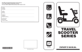
Invacare LYNX LX-3 is a reliable and user-friendly scooter designed to provide you with independence and mobility. With its powerful motor and long-lasting batteries, you can navigate various terrains smoothly and confidently. The adjustable tiller and comfortable seat ensure a personalized and comfortable ride. Safety features like the brake release lever and anti-tip wheels enhance your safety while operating the scooter. Whether you're running errands, exploring your neighborhood, or simply enjoying a leisurely ride, the LYNX LX-3 offers a dependable and enjoyable experience.

Invacare LYNX LX-3 is a reliable and user-friendly scooter designed to provide you with independence and mobility. With its powerful motor and long-lasting batteries, you can navigate various terrains smoothly and confidently. The adjustable tiller and comfortable seat ensure a personalized and comfortable ride. Safety features like the brake release lever and anti-tip wheels enhance your safety while operating the scooter. Whether you're running errands, exploring your neighborhood, or simply enjoying a leisurely ride, the LYNX LX-3 offers a dependable and enjoyable experience.

Unpacking/Setup Instructions
Lynx LX-3
TM
Scooter
DEALER: THIS MANUAL MUST BE GIVEN
TO THE USER OF THE WHEELCHAIR.
USER: BEFORE USING THIS WHEEL-
CHAIR, READ THIS MANUAL AND SAVE
FOR FUTURE REFERENCE.
Instrucciones Para Desempacar y Ensamblar El Escúter
DISTRIBUIDOR: ESTE MANUAL DEBE DE
SER ENTREGADO AL USUARIO DEL
ESCUTER.
USUARIO: ANTES DE USAR EL ESCUTER,
LEA ESTE MANUAL Y GUARDELO PARA
FUTURA REFERENCIA.
2
Tiller
Front Basket
Headlight
On-Board Battery Charger
Floor Basket
Rear Shroud
Seat
LYNX LX-3 SCOOTER
DISASSEMBLED VIEW
Front Basket
Batteries
Rear Sub-Frame
Assembly
Rear Shroud
Seat
Front Sub-Frame
Assembly
LYNX LX-3 SCOOTER
3
Congratulations on the purchase of your new LYNX LX-3 Scooter. To ensure safe and proper operation of
your scooter, DO NOT attempt to operate your scooter without first reading the Owner's Operator and
Maintenance Manual.
Before proceeding, check to ensure that you have three (3) cartons:
One (1) large carton containing the scooter
Two (2) battery cartons
Tools needed for setup and assembly:
7/16 Box Wrench or Crescent Wrench
The use of rubber gloves and safety glasses is recommended when working with batteries.
The instructions contained in this manual were written to provide a step-by-step guide for assembly and setup of
your scooter. A space is provided to check off each step as it is completed.
If you have difficulty with the instructions, or with setup and assembly of your scooter, you may call
Invacare
Customer Service at 1-800-343-6059 for assistance.
A. REMOVING THE SCOOTER FROM THE CARTON (FIGURE 1)
WARNING
The Lynx LX-3 scooter weighs 110-lbs. (50kg) without the batteries. DO NOT attempt to lift a powered
scooter by any removable (detachable) parts. Improper lifting may result in injury to the user or assis-
tants, or damage to the powered scooter.
To properly remove the scooter from the carton, perform the following steps:
Check Box When
Completed
1. Cut along the seams at the end of the carton that is closest to the scooter seat.
2. Lay the end of the carton down (flat) on the floor.
3. Before attempting to roll the scooter out of the carton, you must first place the brake-release lever in
the "OFF" position (DETAIL "A" of FIGURE 1).
4. Raise the seat back to the upright position (DETAIL "B" of FIGURE 1).
5. To roll the scooter out of the carton, grasp the seat back and gently pull the scooter backwards out of
the carton.
6. Locate the Owner's Operator and Maintenance Manual, part number 1090132. You will need to refer
to this manual as a part of the setup procedures and for safe operation and maintenance of your
scooter.
7. Remove the remaining packing and protective covering material from the scooter.
FIGURE 1 - REMOVING THE SCOOTER FROM THE CARTON
Brake
Release
Lever
Rear of
Scooter
Back
(Upright
Position)
Seat
DETAIL "A" DETAIL "B"
REMOVING THE SCOOTER FROM THE CARTON
4
B. TILLER ASSEMBLY (FIGURE 2)
WARNING
Section B is only to accommodate the removal of the front basket from the floor area of the scooter. DO
NOT operate the scooter until the proper tiller adjustment procedure (refer to PROCEDURE 8 of the
Owner's Operator and Maintenance manual, part number 1090132) has been performed after comple-
tion of these setup instructions.
DO NOT insert the key into the ignition while performing these setup instruction - otherwise, injury or
damage may occur.
To raise the tiller assembly, perform the following steps:
Check Box When
Completed
1. Locate the tiller release lever on the lower left side (facing the scooter) of the tiller (FIGURE 2).
2. While supporting the tiller with one (1) hand, push the tiller release lever to the UNLOCKED position
with the other hand (FIGURE 2).
3. Raise the tiller to the upright position and pull the release lever to the LOCKED position, ensuring the
adjustment pin is engaged in one (1) of the five (5) holes in the adjustment plate.
4. Gently pull/push against the tiller to ensure the tiller is securely engaged into the locking mechanism.
5. Remove the keys from the tiller adjustment plate and place in a safe and secure location.
Tiller Release Lever
UNLOCKED
FIGURE 2 - TILLER ASSEMBLY
Tiller Release Lever
LOCKED
Tiller
Adjustment
Plate
Tiller
Adjustment
Pin
NOTE: The tiller adjustment plate shown in FIGURE 2
has three (3) adjustment positions instead of five (5).
TILLER ASSEMBLY
NOTE: The delta tiller is NOT shown.
5
C. FRONT BASKET INSTALLATION (FIGURE 3)
Check Box When
Completed
1. Remove the front basket from the floor area of the scooter.
2. Remove the packing material that held the basket in place for shipping.
3. Remove the following five (5) items from inside the front basket and set aside for future use:
A. AC Power Cord (
NOTE: This is used for battery charging procedure
)
B. Two (2) Anti-Tipper Wheel Assemblies
C. Knob (
NOTE: This is a spare part to be used if a knob is lost
)
D. Nut/Bolt (
NOTE: This is ONLY used for the optional flag or cane holder, save for future use if
optional flag or can holder was not purchased.
)
To properly install the front basket, perform the following steps:
Check Box When
Completed
1. Align the slots of the front basket with the mounting clips located on the front of the tiller (FIGURE 3).
2. Push down on the front basket to secure it in place.
FIGURE 3 - FRONT BASKET INSTALLATION
Front Basket
Slots
Shroud
Of Tiller
Mounting Clips
FRONT BASKET INSTALLATION
6
Check Box When
Completed
4. Remove the two (2) wide "VELCRO
®
like" straps from around the bottom of the frame post - these are
the battery lifting straps and will be used later in the battery installation process. These two (2) straps
are wrapped together and will need to be separated (DETAIL "A" of FIGURE 5).
NOTE: DO NOT remove the narrow "VELCRO
®
like" strap that runs across the back of the scooter - this
is the battery fastening strap.
5. Disconnect the RED connector of the BATTERY wiring harness from the RED connector on the
CONTROLLER wiring harness and set aside (DETAIL "B" of FIGURE 5).
6. Disconnect the BLACK connector of the BATTERY wiring harness from the BLACK connector on the
CONTROLLER wiring harness and set aside (DETAIL "B" of FIGURE 5).
FIGURE 4 - PREPARING THE SCOOTER/BATTERIES FOR INSTALLATION
Seat
DETAIL "B"DETAIL "A"
Seat Post
Frame Post
Stability
Knob
Rear
Shroud
Frame
Support
VELCRO
®
is a registered trademark of Velcro Industries B.V.
D. BATTERY INSTALLATION
Preparing The Scooter/Batteries For Installation (FIGURES 4, 5 AND 6)
To properly prepare the scooter/batteries for installation, perform the following steps:
Check Box When
Completed
1. Unscrew and remove the stability knob located under the seat on the front of the frame post (DETAIL
"A" of FIGURE 4).
WARNING
DO NOT lift the seat by the arm rests - otherwise, injury or damage may occur.
2. Lift the seat assembly up and remove it from the frame support (DETAIL "A" of FIGURE 4).
3. Lift the rear shroud off of the frame post (DETAIL "B" of FIGURE 4).
NOTE: You will hear a "VELCRO
®
like" unhooking sound when removing the shroud.
BATTERY INSTALLATION
7
WARNING
BEFORE PROCEEDING WITH THE BATTERY INSTALLATION, READ THE FOLLOWING:
To ensure safe handling and that the proper procedures are followed for the battery installation, refer to
BATTERIES AND CHARGING in PROCEDURE 4 of the Owner's Manual, part number 1090132. Once you
have read and understand PROCEDURE 4 in the Owner's Manual, you may proceed with the following
instructions.
Check Box When
Completed
7. Locate the two (2) battery boxes and carefully remove the batteries from the boxes.
NOTE: The weight of each battery is 23 lbs. (10 Kg.).
8. Locate one (1) of the two (2) wide "VELCRO
®
like" battery lifting straps (Refer to STEP 4 of this
procedure) and place it smooth side up (hook side down) on a flat surface (FIGURE 6).
9. Place one (1) of the batteries, front to back, on top of the strap by making sure the following occurs:
A. The two (2) battery terminal posts are on the TOP, REAR edge of the battery (FIGURE 6).
B. The retaining ring on the battery lifting strap is located at the BACK, REAR edge of the battery
(FIGURE 6).
10. Wrap the battery lifting strap around the battery, making sure it runs BETWEEN the two (2) battery
terminal posts (FIGURE 6).
11. Pull the end of the battery lifting strap WITHOUT the retaining ring THROUGH the retaining ring at the
opposite end of the battery lifting strap (FIGURE 6).
NOTE: When the lifting strap is pulled tight, the retaining ring should be positioned in the MIDDLE of the
BACK side of the battery.
12. If necessary, adjust the battery lifting strap by placing one (1) hand BETWEEN the battery lifting strap
and the TOP of the battery, then secure the remaining loose end by pressing the "VELCRO
®
like"
material together.
13. Test that the battery is secure and positioned properly for lifting and transporting by using two (2)
hands (one (1) hand under the strap on the TOP of the battery, and the other to balance the battery)
to carefully lift the battery.
FIGURE 5 - PREPARING THE SCOOTER/BATTERIES FOR INSTALLATION
DETAIL "B"DETAIL "A"
RED
Connector
Battery Lifting Straps
(Remove From Around
Frame Post)
Battery Fastening
Strap (DO NOT
Remove)
BLACK
Connector
Rear Sub
Frame
Battery Wiring Harness
RED
Connector
BLACK
Connector
Controller
Wiring
Harness
Preparing The Scooter/Batteries For Installation (FIGURES 4, 5 AND 6) - Continued
BATTERY INSTALLATION
VELCRO
®
is a registered trademark of Velcro Industries B.V.
Battery
Wiring
Harness
8
Connecting The Battery Wiring Harness To The Battery (FIGURES 7 AND 8)
To properly connect the battery wiring harness to the battery, perform the following steps:
Check Box When
Completed
1. Locate the battery wiring harness with the BLACK connector at one (1) end (FIGURE 7).
NOTE: There are two (2) battery wiring harnesses - one (1) with a BLACK connector and one (1) with a
RED connector.
CAUTION
When tightening the screws/locknuts on the battery terminal posts, always use a box or a crescent
wrench. Pliers will round off the nuts. Never wiggle the terminal when tightening. Otherwise, the battery
may become damaged.
2. Remove the mounting screw and locknut from the NEGATIVE (-) battery terminal post (FIGURE 8).
NOTE: To establish a ground, make the BLACK cable to NEGATIVE (-) battery terminal post connection first.
3. Connect the battery cable with the BLACK boot to the NEGATIVE (-) battery terminal post using the mounting
screw and locknut (FIGURE 8). Tighten the screw and locknut using a 7/16 box or Crescent wrench.
4. Push the BLACK battery cable boot down over the NEGATIVE (-) battery terminal post, covering the
terminal post, mounting screw and locknut (FIGURE 8).
FIGURE 7 - CONNECTING THE BATTERY WIRING HARNESS TO THE BATTERY
Battery
Wiring
Harness
Black
Connector
Battery
Wiring
Harness
Red
Connector
FIGURE 6 - PREPARING THE SCOOTER/BATTERIES FOR INSTALLATION
Battery
Lifting
Strap
Smooth Side Up
Battery
Battery
Terminal Post
(NOT
SHOWN)
Battery
Terminal Post
(NOT
SHOWN)
Top,
Rear
Edge
Battery
Lifting
Strap
Retaining
Ring
Preparing The Scooter/Batteries For Installation (FIGURES 4, 5 AND 6) - Continued
NOTE: DO NOT position the battery in the scooter at this time.
14. Repeat STEPS 7-14 for the other battery.
BATTERY INSTALLATION
9
Installing The Batteries Into The Scooter (FIGURES 9, 10, 11 AND 12)
To properly install the batteries into the scooter, perform the following steps:
Check Box When
Completed
1. Loosen the battery fastening strap, making sure that both ends of the battery fastening strap are
laying outside of the scooter so the batteries will not be set down on the battery fastening strap
(FIGURE 8).
2. Ensure the area behind the floor basket (where the batteries will be installed) is free of all material and
ready for the batteries to be installed.
3. Remove the retaining pin that holds the front frame assembly and the rear frame assembly together
(FIGURE 10).
4. Temporarily place the retaining pin inside the frame post (FIGURE 10).
NOTE: DO NOT lift up on either the front or rear frame assemblies when the pin is removed. Otherwise,
the front frame will separate from the rear frame.
Battery
Fastening
Strap
Laying On
Outside Of
Scooter
FIGURE 9 - INSTALLING THE BATTERIES INTO THE SCOOTER
Connecting The Battery Wiring Harness To The Battery (FIGURES 7 AND 8) - Continued
5. Remove the mounting screw and locknut from the POSITIVE (+) battery terminal post
6. Connect the battery cable with the RED boot to the POSITIVE (+) battery terminal post using the
mounting screw and locknut. Tighten the screw and locknut using a 7/16 box or Crescent wrench.
7. Push the RED battery cable boot down over the POSITIVE (+) battery terminal post, covering the
terminal post, mounting screw and locknut.
8. Locate the battery wiring harness with the RED connector at one (1) end (FIGURE 7).
9. Repeat STEPS 2-8 for the second battery.
FIGURE 8 - CONNECTING THE BATTERY WIRING HARNESS TO THE BATTERY
Mounting Screws
Locknuts
Battery Wiring
Harness With
Black Connector
Battery Cable
Black Boot
Positive (+) Battery Terminal Post
Negative (-) Battery
Terminal Post
Battery Cable
Red Boot
BATTERY INSTALLATION
10
NOTE: DO NOT put the pin into the large hole in the frame post.
8. Ensure that the area where the second battery is to be installed is free of all material and ready for the
battery to be installed.
9. Locate the battery with the RED connector at the end of the battery wiring harness.
10. Carefully lift the battery using the battery lifting strap (using one (1) hand under the strap on the TOP
of the battery, and the other to balance the battery) and place it in the open area just behind the LEFT
side of the floor basket (FIGURE 11).
NOTE: The battery terminals should be towards the rear of the scooter (FIGURE 11).
NOTE: DO NOT connect the battery wiring harness at this time.
FIGURE 11 - INSTALLING THE BATTERIES INTO THE SCOOTER
Front Of Scooter
Rear Of Scooter
TOP VIEW OF REAR PORTION OF SCOOTER
Battery Terminals
Battery Terminals
Battery
Black Connector
Battery Wiring Harness
Battery
Red Connector
Battery Wiring Harness
Installing The Batteries Into The Scooter (FIGURES 9, 10, 11 AND 12) - Continued
Retaining Pin
Frame Post
Place Retaining Pin Here
5. Locate the battery with the BLACK connector at the end of the battery wiring harness.
6. Carefully lift the battery using the battery lifting strap (using one (1) hand under the strap on the TOP
of the battery, and the other to balance the battery) and place it in the open area just behind the
RIGHT side of the floor basket (FIGURE 11).
NOTE: The battery terminals should be towards the rear of the scooter (FIGURE 11).
NOTE: DO NOT connect the battery wiring harness at this time.
7. From the rear of the scooter, replace the retaining pin by passing it through both the FRONT and the
REAR frame assemblies (FIGURE 10).
FIGURE 10 - INSTALLING THE BATTERIES INTO THE SCOOTER
Front Frame Assembly
Rear Frame Assembly
BATTERY INSTALLATION
11
Installing The Batteries Into The Scooter (FIGURES 9, 10, 11 AND 12) - Continued
11. Reconnect the battery fastening strap by pulling the loose end though the retaining ring and tighten-
ing the strap (FIGURE 12).
NOTE: Ensure that none of the wiring harnesses are under the strap (between the strap and the battery).
Connecting The Battery Wiring Harness (FIGURE 13)
To properly install the batteries into the scooter, perform the following steps:
WARNING
NEVER allow any of your tools and/or battery cables to contact BOTH terminal(s) post(S) at the same
time. An electrical short may occur and injury or damage may result.
Check Box When
Completed
1. Connect the BLACK connector of the battery wiring harness to the BLACK connector of the controller
wiring harness. Push together until the connectors lock together (FIGURE 13).
2. Connect the RED connector of the battery wiring harness to the RED connector of the controller
wiring harness. Push together until the connectors lock together (FIGURE 13).
FIGURE 13 - CONNECTING THE BATTERY WIRING HARNESS
Black Connector
Battery Wiring Harness
Black Connector
Controller Wiring Harness
Controller
Red Connector
Battery Wiring Harness
Red Connector
Controller Wiring Harness
Batteries
FIGURE 12 - INSTALLING THE BATTERIES INTO THE SCOOTER
Battery
Fastening
Strap
Retaining
Ring
BATTERY INSTALLATION
12
E. ANTI-TIPPER WHEEL ASSEMBLY INSTALLATION (FIGURE 14)
WARNING
DO NOT operate the scooter without the anti-tipper wheel assemblies installed. Anti-tipper wheel as-
semblies MUST be attached at all times - otherwise, injury or damage may occur.
Check Box When
Completed
1. Locate the two (2) anti-tipper wheel assemblies.
2. From the REAR of the scooter, remove the quick release pin on the LEFT side of the scooter sub-
frame assembly (FIGURE 14).
3. Slide the anti-tipper wheel assembly into the LEFT side of the sub-frame assembly and secure with
the quick release pin. Ensure the quick release pin is protruding through the bottom of the sub-frame
assembly (FIGURE 14).
NOTE: To check for proper installation, the anti-tipper wheel should be facing the inside of the scooter and
the warning label should face the outside of the scooter (FIGURE 14).
4. Repeat STEPS 2-3 for the RIGHT side anti-tipper wheel assembly.
FIGURE 14 - ANTI-TIPPER WHEEL INSTALLATION
Sub-Frame Assembly
Anti-Tipper
Wheel Assembly
Quick
Release
Pin
Wheel (Facing
Inside Of
Scooter)
Warning Label
(Facing Outside
Of Scooter)
ANTI-TIPPER WHEEL ASSEMBLY INSTALLATION
13
F. REASSEMBLY OF THE REAR SHROUD AND SEAT (FIGURE 15)
Check Box When
Completed
1. Check to ensure the wiring harness in NOT covering the "VELCRO
®
like" strip on TOP of the rear
frame assembly.
2. Place the rear shroud over the frame post (DETAIL "A" of FIGURE 15).
3. Pick up the seat assembly and place the seat post into the frame post and lower the seat into position
(DETAIL "B" of FIGURE 15)
4. Screw the stability knob into the hole located on the FRONT of the frame post, Hand tighten ONLY
(DETAIL "B" of FIGURE 15)
WARNING
The stability knob is designed to prevent the seat from "wiggling" back and forth. DO NOT use the
stability knob to adjust the seat height as it will NOT support the weight of the seat/user. To adjust the seat
height, refer to
ADJUSTING THE SEAT HEIGHT in PROCEDURE 5 of the Owner's Manual, part number
1090132. Otherwise, injury or damage may occur.
NOTE: Refer to the PROCEDURE 5 of the Owner's Manual, part number 1090132, for proper seat
adjustments.
VELCRO
®
is a registered trademark of Velcro Industries B.V.
FIGURE 15 - REASSEMBLY OF THE REAR SHROUD AND SEAT
Seat
DETAIL "B"DETAIL "A"
Seat Post
Frame Post
Stability
Knob
Rear
Shroud
Frame
Support
REASSEMBLY OF THE REAR SHROUD AND SEAT
14
Although you have now completed the setup and assembly instructions - DO NOT INSERT THE KEY INTO THE
IGNITION AT THIS TIME.
New batteries MUST be fully charged prior to the initial use of the scooter, otherwise battery life will be
reduced.
Your LYNX LX-3 Scooter has an on-board battery charger. Refer to
CHARGING THE BATTERIES in PROCE-
DURE 4 of the Owner's Manual, part number 1090132.
While the batteries in your scooter are charging, it is recommended that you do the following:
Read the Owner's Operator and Maintenance Manual, part number 1090132
WARNING
DO NOT operate your scooter without first reading and understanding your Owner's Manual. If you are
unable to understand the warning, cautions and instructions, contact Invacare Customer Service
(1-800-343-6059) before attempting to use this equipment - otherwise, injury or damage may result.
CUSTOMER SURVEY
15
Barra del Timón
Canasta de Enfrente
Farol
Cargador de la Batería de Abordo
Canasta del Piso
Covertura Trasera
Asiento
ESCUTER LYNX LX-3
VISTA DESARMADO
Baterías
Subestructura Trasera
Covertura Trasera
Asiento
Subestructura
Delantera
ESCUTER LYNX LX-3
Canasta de Enfrente
16
Congratulaciones por la compra de su nuevo Escúter LYNX LX-3. Para asegurarse de operar su escúter
de manera aporpiada y sin peligros, NO intente operarlo sin antes leer el Manual del Operador y de
Mantenimiento..
Antes de proceder, inspeccone para asegurarse de que ha recibido tres (3) cajas:
Una (1) caja grande contiene el escúter
Dos (2) cajas contien las baterias
Herramientas necesarias para armar y ensamblar:
Llave de Tubo de 7/16" o llave Crescent
Se recomienda el uso guantes y anteojos protectores cuando trabaje con baterías.
Las instrucciones contenidas en este manual fueron escritas para proveer una guía paso a paso para el armado y
ensamblado de su escúter. Se provee un espacio en el manual para que vaya marcando cada paso que haya completado.
Si tiene dificultad para entender las instrucciones, con el armado y ensamblado de su escúter, puede llamar al
Departamento
Para Servicio a los Clientes de Invacare al teléfono número 1-800-343-6059, para obtener asistencia.
A. REMOVIENDO EL ESCUTER DE LA CAJA (FIGURA 1)
ADVERTENCIA
El escúter Lynx LX-3 pesa 110-lbs. (50kg) sin las baterías. NO intente levantar el escúter motorizado
de una parte que es removible (que se desprende). Al levantarlo de manera impropia puede
resultar en herida al usuario o asistentes, o daño al escúter.
Para remover el escúter de la caja apropiadamente, siga los pasos siguientes:
Marque el Espacio
Cuando Haya
Completado
1. Corte la caja en la orilla del lado que está más cerca del asiento del escúter.
2. Recueste la caja en el piso (a nivel).
3. Antes de intentar sacar el escúter de la caja, mueva la palanca de soltar el freno a la posición "OFF"
(DETALLE "A" de FIGURA 1).
4. Levante el respaldo del asiento a su posición recta (DETALLE "B" de FIGURA 1).
5. Para sacar el escúter de la caja, agarre el respaldo del asiento y con mucho cuidado jale el escúter
hacia atrás.
6. Localice el Manual del Operador y Mantenimiento, número 1090132. Necesitara este manual para
referirse a los procedimientos, para una operación sin peligros y el mantenimiento del escúter.
7. Remueva el resto del material de empaque y protección del escúter.
FIGURA 1 - REMOVIENDO EL ESCUTER DE LA CAJA
Palanca
de Soltar
el Freno
Parte de
Atrás del
Escúter
Respaldo
(Posición
Recta)
Asiento
DETALLE "A" DETALLE "B"
REMOVIENDO EL ESCUTER DE LA CAJA
17
B. ENSAMBLE DE LA BARRA DEL TIMON (FIGURA 2)
ADVERTENCIA
La Sección B es solamente para hacer lugar para la remoción de la canasta de enfrente, que
viene en el area del piso del escúter. NO opere el escúter hasta que el ajuste apropiado de la barra
del timón esté hecho, después de completar estas instrucciones. (refiérase a PROCEDIMIENTO 8 del
Manual del Operador y de Mantenimiento, número 1090132).
NO inserte la llave a la ingnición mientras lleva acabo estas instrucciones de ensamblado. Do otro
modo, herida personal o daño pueden ocurrir.
Para levantar el ensamble de la barra del timón, siga los siguientes pasos.
Marque el espacio
Cuando Haya
Completado
1. Localice la palanca de abrir la cerradura de la barra del timón, abajo, lado izquierdo (viendo al escúter de
frente) de la barra del timón (FIGURA 2).
2. Mientras sostiene la barra del timón con una (1) mano, empuje la palanca de abrir la cerradura a la
posición "UNLOCKED" con la otro mano. (FIGURA 2).
3. Levante la barra del timón a su posición recta y jale la palanca hacia la posición "LOCKED",
assegurandose de que el pasador ha entredo en uno (1) de los cinco (5) hoyos de la plancha para los
ajustes.
4. Cuidadosamente empuje y jale la barra del timón para ver si está bien asegurada en el mecanismo.
5. Remueva las llaves de la plancha de ajustar la barra del timón y coloquelas en un lugar seguro.
Palanca de Abrir la
Cerradura de la Barra del
Timón - SEGURO ABIERTO
FIGURA 2 - ENSAMBLE DE LA BARRA DEL TIMON
Palanca de Abrir la Cerradura
de la Barra del Timón -
SEGURO CERRADO
Plancha de
Ajustar la Barra
del Timón
Barra del
Timón
Pasador
NOTA: La plancha de ajustar la barra del timón que se
muestra en la FIGURA 2 tiene tres (3) posiciones de
ajuste en lugar de cinco (5).
ENSAMBLE DE LA BARRA DEL TIMON
NOTA: La barra del timón delta NO se muestra.
18
C. INSTALACION DE LA CANASTA DE ENFRENTE (FIGURA 3)
Marque el Espacio
Cuando Haya
Completado
1. Remueva la canasta de enfrente del area del piso del escúter.
2. Remueva el material de empaque que mantubo la canasta sujeta durante el envío.
3. Remueva las siguientes cinco (5) cosas que se encuentran dentro de la canasta y póngalas a un lado
para uso futuro.
A. Cordón eléctrico (
NOTA: Este se usa en el procedimiento de cargar la batería
)
B. Dos (2) ensambles de ruedas antivuelco
C. Perilla (
NOTA: Esta es una parte de repuesto en caso de que pierda la primera
)
D. Tuerca/Tornillo (
NOTA: Este se usa SOLAMENTE para la bandera opcional o el sostenedor de
un bastón. Guardelos para futuro uso si no compró ahora una vandera o un bastón
)
Para instalar apropiadamente la canasta de enfrente, siga los siguentes pasos:
Marque lols Espacios
Cuando Haya
Completado
1. Alinie las aberturas del frente de la canasta con los sostenedores localizados en el frente de la barra del
timón. (FIGURA 3).
2. Empuje la canasta hacia abajo, para que trabe y quede en su lugar.
FIGURA 3 - INSTALACION DE LA CANASTE DE ENFRENTE
Canasta de Enfrente
Aberturas
Covertura del Timón
Sostenedores
INSTALACION DE LA CANASTA DE ENFRENTE
19
Marque el Espacio
Cuando Haya
Completado
4. Remueva las dos (2) correas anchas "VELCRO
®
" que se encuentran alrededor, abajo del tubo soporte
Estas son las correas de levantar las baterías y serán usadas más tarde en el proceso de instalar las
baterías. Estas dos (2) correas están enrolladas juntas y se necesitará separarlas. (DETALLE "A" de
FIGURA 5).
NOTA: NO remueva la correa angosta "VELCRO
®
" que está instalada a través de la parte trasera del
escúter. Esta es la correa de sujetar la batería.
5. Desconecte el conector ROJO del arnés de la BATERIA, del conector ROJO del arnés del CONTROL
y déjelo a un lado (DETALLE "B" de FIGURA 5).
6. Desconecte el conector NEGRO del arnés de la BATERIA, del conector NEGRO del arnés del CON-
TROL y déjelo a un lado (DETALLE "B" de FIGURA 5).
FIGURA 4 - PREPARANDO EL ESCUTER Y LAS BATERIAS PARA LA INSTALACION
Asiento
DETALLE "B"DETALLE "A"
Paral
Tubo Soporte
Botón
Estabilizador
Covertura
Trasera
Soporte de
La Estructura
VELCRO
®
es una marca registrada de Velcro Industries B.V.
D. INSTALACION DE LAS BATERIAS
Preparando El Escúter y las Baterías Para la Instalación (FIGURAS 4, 5 y 6)
Para preparar el escúter y las baterías para la instalación apropiada, siga los pasos siguientes:
Marque el Espacio
Cuando Haya
Completaddo
1. Desatornille y remueva el botón estabilizador localizado debajo del asiento en el tubo soporte.(DETALLE
"A" de FIGURA 4).
ADVERTENCIA
NO levante el asiento por los brazos. De otra manera, herida o daño pueden ocurrir.
2. Jale el asiento hacia arriba y remuevalo del tubo soporte (DETALLE "A" de FIGURA 4).
3. Levante la covertura trasera, separela del tubo soporte.(DETALLE "B" de FIGURA 4).
NOTA: Se escuchará un sonido como si separara un "VELCRO
®"
cuando remueva la covertura trasera.
INSTALACION DE LAS BATERIAS
20
ADVERTENCIA
ANTES DE PROCEDER CON LA INSTALACION DE LA BATERIA, LEA LO SIGUIENTE:
Para asegurarse de seguir el procedimiento apropiado y que usa los cuidados necesarios en el
proceso de la instalación de la batería, refiérase a
BATERIAS/CARGANDOLAS en el PROCEDIMIENTO
4 del Manual del Usuario, número 1090132. Cuando haya leído y entendido el PROCEDIMIENTO 4
en Manual del Usuario, puede proceder con las siguientes instrucciones.
Marque el Espacio
Cuando Haya
Completado
7. Localice las dos (2) cajas que contienen las baterías y cuidadosamente remueva las baterías.
NOTA: El peso de cada batería es de 23 libras. (10 Kg.).
8. Localice una (1) de dos (2) correas anchas "VELCRO
®
" para levantar las baterías (Refiérase a PASO
4 de este procedimiento) y coloque el lado liso hacia arriba (ganchos viendo hacia abajo) en una
superficie plana (FIGURA 6).
9. Coloque una (1) de las baterías (1) con el fente viendo hacia atrás, sobre la correa, asegurandose de
que ocurre lo siguiente:
A. Las dos (2) terminales de la batería quedan ARRIBA, en la orilla de ATRAS de la batería. (FIGURA 6).
B. El anillo retenedor de la correa de levantar la batería queda ATRAS, en la orilla de ATRAS de la
batería (FIGURA 6).
10. Ponga la correa alrededor de la batería, asegurandose de que ésta pasa EN MEDIO de las dos (2)
terminales de la batería (FIGURA 6).
11. Jale la punta de la correa QUE NO TIENE el anillo retenedor A TRAVES del.anillo retenedor que se
encuentra en la otra punta de la correa (FIGURA 6).
NOTA: Cuando la correa de levantar la batería sea apretada, el anillo retenedor de la misma debe de
quedar EN MEDIO del lado de ATRAS de la batería.
12. Si es necesario, ajuste la correa mediante colocar una (1) mano ENTRE la correa y el lado de ARRIBA
de la batería, y entonces asegure la punta que está floja mediante presionar el material "VELCRO
®
"
para que agarre.
FIGURA 5 - PREPARANDO EL ESCUTER Y LAS BATERIAS PARA LA INSTALACION
DETALLE "B"DETALLE "A"
Conector
ROJO
Correas de Levantar las
Baterías (Remuevalas
de Alrededor del Tubo
Soporte)
Correa de Sujetar
la Batería (NO
Remueva)
Conector
NEGRO
Subestructura
Trasera
Arnés de la Batería
Conector
ROJO
Conector
NEGRO
Arnés del
Control
Preparando El Escúter y Las Baterías Para La Instalación (FIGURAS 4, 5 Y 6) - Continuación
INSTALACION DE LAS BATERIAS
VELCRO
®
es una marca registrada de Velcro Industries B.V.
Arnés de la
Batería
  • Page 1 1
  • Page 2 2
  • Page 3 3
  • Page 4 4
  • Page 5 5
  • Page 6 6
  • Page 7 7
  • Page 8 8
  • Page 9 9
  • Page 10 10
  • Page 11 11
  • Page 12 12
  • Page 13 13
  • Page 14 14
  • Page 15 15
  • Page 16 16
  • Page 17 17
  • Page 18 18
  • Page 19 19
  • Page 20 20
  • Page 21 21
  • Page 22 22
  • Page 23 23
  • Page 24 24
  • Page 25 25
  • Page 26 26
  • Page 27 27
  • Page 28 28

Invacare LYNX LX-3 Unpacking And Setup Instructions

Category
Scooters
Type
Unpacking And Setup Instructions

Invacare LYNX LX-3 is a reliable and user-friendly scooter designed to provide you with independence and mobility. With its powerful motor and long-lasting batteries, you can navigate various terrains smoothly and confidently. The adjustable tiller and comfortable seat ensure a personalized and comfortable ride. Safety features like the brake release lever and anti-tip wheels enhance your safety while operating the scooter. Whether you're running errands, exploring your neighborhood, or simply enjoying a leisurely ride, the LYNX LX-3 offers a dependable and enjoyable experience.

Ask a question and I''ll find the answer in the document

Finding information in a document is now easier with AI

in other languages