Raven Phoenix 50 Installation & Operator's Manual
- Category
- GPS receiver modules
- Type
- Installation & Operator's Manual

Phoenix 50 Installation & Operator’s
Manual
P/N 016-0171-211 Rev A 06/15
Copyright 2009

While every effort has been made to ensure the accuracy of this document,
Raven Industries assumes no responsibility for omissions and errors. Nor is any
liability assumed for damages resulting from the use of information contained
herein.
Raven Industries shall not be held responsible or liable for the effects of
atmospheric conditions and sunspot activity on the performance of our products.
Raven Industries cannot guarantee the accuracy, integrity, continuity, or
availability of the GPS signal from the U.S. Department of Defense/NAVSTAR
GPS satellites, the OmniSTAR correction service or the WAAS correction
service.
Raven Industries accepts no responsibility for the use of the signal for other than
the stated purpose. Raven Industries shall not be responsible or liable for
incidental or consequential damages or a loss of anticipated benefits or profits,
work stoppage or loss or impairment of data arising out of the use, or inability to
use, the SmarTrax or any of its components.
Disclaimer

1
INTRODUCTION
Congratulations on your purchase of the Raven Phoenix 50 GPS Receiver. This compact, all in one
unit, will provide you with the ability to log data and provide speed to your Raven controller. Setup
is fast and easy and can have you in the field within a half hour
, in most cases. This manual will assist
you in installing your Phoenix 50 GPS receiver.
Note: This receiver should not be used for steering systems, since it is only a 4 Hz receiver.
GPS RECEIVER
The Phoenix 50 GPS receiver can generate real-time position solutions at a rate of 4 solutions per
second. Position solutions are output via RS232 in NMEA format messages.
The Phoenix 50 has two RS232 ports and can communicate at 1200, 2400, 4800, 9600, 19.2k, 38.4k,
57.6k, or 115.2k BPS. The baud rate and the desired output messages can be configured via either
serial port using configuration messages.
NMEA format messages are standard for most GPS receivers and therefore should be compatible
with almost any software or hardware application designed to work with GPS.
The receiver comes from the factory with message settings that should be compatible with most
applications. Refer to the connecting equipment manuals for information about what message types
and serial settings they require.
DEFAULT SERIAL SETUP
PORT
NMEA
MESSAGE
MESSAGE
RATE
BAUD RATE
A
GGA, VTG
ZDA
4 Hz
200mHz
19200 BPS
B
GGA, VTG
ZDA
4 Hz,
200mHz
19200 BPS

2
WAAS RECEIVER
The Phoenix 50 provides real time differential solutions using free corrections (WAAS) broadcast
from a satellite. WAAS corrections are available without a subscription free everywhere in the US,
parts of Canada, Mexico and Europe using a compatible system called EGNOS. These corrections
are available 24 hours a day in all weather conditions.
UTILITY SOFTWARE
Utility software is not required to setup or use the receiver in most applications. However, a utility
program is available from Raven. See Receiver Firmware Updates for Software location.
RECEIVER FIRMWARE UPDATES
Firmware is software, which resides inside the receiver. Raven continues to improve the performance
of its receiver products and sometimes makes special features available. When this happens, a new
version of firmware is created. A request can be made for this firmware from Raven. It will be neces-
sary to connect the receiver to a PC and run the included programming software to update the unit.
Check with a Raven dealer for a new version of firmware. Make sure to read the updated directions
included with the latest download.
Firmware and upgrade utilities may be obtained at the following locations:
main download page:
http://www.ravenprecision.com/us/Support/Software/
Receiver page:
http://www.ravenprecision.com/us/Support/Software/softwareCategory.jsp?ID=1
SPECIAL FEATURES
The Phoenix 50 has several special features that make it ideal for some applications. Raven is always
interested in adding special features to the receiver. If you have a good idea, please send us an email
at
[email protected] or give us a call at 800-243-5435. We can’t guarantee that your idea will be
implemented, but we do want to consider it.

3
RADAR OUT
The GPS receiver is always calculating speed and can generate the signals, which can be used by
equipment requiring RADAR input. The receiver is normally configured at the factory for RADAR out-
put.
To use this feature, a special cable from Raven will be needed. It should be noted that the GPS can
only determine speed when it is navigating. If a tree line blocks too many satellites or if for some other
reason the receiver is unable to navigate, then the RADAR output could become invalid.
The scaling factors and timing controls that govern the operation of this feature can be controlled via
a serial configuration message as defined in the serial Protocol Definition document. The receiver
outputs a default of 45Hz per 1mph.
INSTALLATION
Start by selecting a location for each of the various parts of the system. Do not route the cables or
permanently mount the Phoenix 50 receiver yet. Once the system is operating, route the cables and
permanently mount the Phoenix 50 receiver. This will reduce the amount of trouble if a problem is
found in the initial locations.
INITIAL POWER UP
Phoenix 50 receivers are reverse power protected to prevent damage to the receiver if you follow
these steps:
Turn off all the equipment on the machine. The receiver draws very little power and this test will only
take a few minutes. All other equipment should be off because it might interfere with the receiver.
Once the Phoenix 50 is working, turn on the other equipment and watch for problems.
Apply power to the receiver by connecting the black wire to the negative (-) and the red wire to the
positive (+) post on the power source (most likely the battery). To check power connections connect a
lightbar or some other serial interface device to the Phoenix 50 receiver. If attached to a lightbar, it
should light up when power is applied to the receiver. If using a serial interface device, look for NMEA
strings such as GGA to scroll across the screen. If none of these things respond remove the red and
black wires from the power source and check the connections again. If in a car or Ag machine, try
turning the key on. If still having trouble refer to the power section below or call our technical support
line.
Once the receiver power is connected correctly go ahead and shut the power off. Mount the Phoenix
50 and repeat the previous step.

4
At this point, the power is connected to the mounted receiver. The Phoenix 50 will be looking for
satellites, which may take a few minutes. Eventually, if the antenna has a clear view of the sky, the
receiver will send data to the lightbar or other serial interface devise.
Wait for the receiver to find and track the WAAS signal, it could take 15 or more minutes before the
receiver gets the necessary almanac data from the selected WAAS satellite. This initial startup time is
necessary only during the first time the receiver is used. Once the broadcast is found the receiver will
power up and start receiving signals after about 20 seconds. If a signal is not received within about 30
minutes there could be some form of interference or the receiver may not be in the coverage area of
the selected WAAS satellite.
At this point, the receiver should be tracking satellites and generating good differential position. Start
turning on other equipment on the machine. A device could interfere with the GPS satellites or WAAS
signals. Wait about 30 seconds after each device is turned on to see if the receiver stops tracking
satellites. Finally, start up the machine and again watch for any problems.
If after turning something on, a problem is found, try moving the antenna further away from that device.
Check that the device is functioning properly and also check its power connections. Some devices
can generate too much noise naturally or because of defective components.
Now the receiver is working with everything that could interfere. Shut everything off, mount the re-
ceiver, and route the cables. Once this is done, repeat the power up steps.
The last few steps deal with connecting the other equipment that gets data from the Phoenix 50. Refer
to the manufacturer’s documentation for details such as baud rates and required messages. It is very
likely it will only be necessary to connect the interface cables to the device. The Phoenix 50 is config-
ured, by default, to work with most systems without any adjustments.
All configuration and WAAS data is stored in non-volatile memory inside the Phoenix 50. If it is neces-
sary to change the WAAS or GPS setups, run the receiver software to make the changes.
POWER
The Phoenix 50 receiver needs DC power between 9 and 16 Volts. DC power is usually provided by
battery on the machine or via a power adapter of some type. If the unit came with an automotive
power adapter, verify that the vehicle has a negative ground system before connecting power. If the
unit came with an AC adapter, it will be necessary to only connect the adapter to an AC source.

5
GPS ANTENNA
GPS is a line of sight system, which means in order for the receiver to track the satellites there must
be an unobstructed path directly to them. Buildings, trees, machinery, and human bodies are common
obstructions. When locating the antenna/receiver find a place where the antenna will have an unob-
structed view of the sky. Items such as electrical motors, generators, alternators, strobe lights, radio
transmitters, cellular phones, microwave dishes, radar, active antennas, etc., all generate electrical
and magnetic fields which can interfere with the GPS or WAAS signal. Mount the Antenna/receiver
away from such potential sources of interference.
The GPS can be de-tuned by close proximity to other objects. For example, if you place the antenna
under fiberglass its performance could be degraded. Usually, if the antenna/receiver is lowered so that
at least a quarter of an inch gap is made between the antenna/receiver and the covering plastic or
fiberglass, acceptable performance can be achieved. Metal or other dense materials will completely
block the GPS signals.
TROUBLESHOOTING
· Make sure the antenna is mounted so that it has a clear view of the sky and is as far away from
electrical noise sources as possible.
Attempt to isolate all problems as either:
· Receiver/Antenna
· Power
· Transmitting Site
· Serial Communications
· Peripheral Device
CHECKING YOUR INSTALLATION
Monitor the effects on the GPS receiver performance as each device on the vehicle is powered on. If
the receiver stops operating properly when a device is powered on, that device is causing interference
and the receiver location may need to change. For example, if running the engine causes interference,
then ignition noise or alternator noise is interfering with signal reception. Move the receiver further
away from the engine.
Receiver – Normally only 5 GPS satellites are required for good accuracy. If a lightbar is connected,
ensure the 3 center LED are green.
Transmitting – If the receiver is operating in WAAS mode, the receiver may be out of range of a satellite
or the satellite may be off the air. WAAS status information is available on the Internet at
http://www.nstb.tc.faa.gov/RT_WaasSatelliteStatus.htm or http://www.omnistar.com/space/index.html
Serial Coms – Using RFP Sim software, check for proper communication settings baud rate, and
COM port number. Make sure the cable used, if not provided by Raven, is wired
correctly. See section titled “serial Interface.”

6
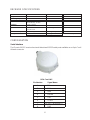
RECEIVER SPECIFICATIONS
Size 2.1 x 5.09 Protocols NMEA v2.2
Weight 18 ounces
Operating Temperature -40°C to +70°C
Operating Humidity 5% to 95% R.H.,
Non-condensing, at +60°C
Channels 12 GPS, 1 WAAS
Update Rate 4/second Port A Mounting Magnetic
4/second Port B
Power Consumption 3 - 2 Watts Typical Storage Temp. -40°C to +85°C
Voltage 9-16 VDC Storage Humid. 100% Condensing
CONFIGURATION
Serial Interface
The Phoenix 50 GPS receiver has two bi-directional RS232 serial ports available on an 8-pin Con-X-
All male connector.
8-Pin Con-X-All
Pin Number Signal Name
1 TXA
2 RXA
3 GND
4 RADAR
5 TXB
6 12 VDC
7 +12 VDC Pwr Output RT
8 RXB

7
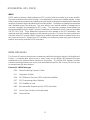
GLOBAL POSITIONING SYSTEM (GPS)
GPS is a satellite-based global navigation system created and operated by the United States Department
of Defense (DOD). Originally intended solely to enhance military defense capabilities, GPS capabilities
have expanded to provide highly accurate position and timing information for many civilian applications.
An in-depth study of GPS is required to fully understand it, but not to see how it works or appreciate
what it can do for you. Simply stated, thirty-two satellites in six orbital paths circle the earth twice each
day at an inclination angle of approximately 55 degrees to the equator. This constellation of satellites
continuously transmits coded positional and timing information at high frequencies in the 1500
Megahertz range. GPS receivers with antennas located in a position to clearly view the satellites pick
up these signals and use the coded information to calculate a position in an earth coordinate system.
GPS is the navigation system of choice for today and many years to come. While GPS is clearly the
most accurate worldwide all-weather navigation system yet developed, it still can exhibit significant
errors. GPS receivers determine position by calculating the time it takes for the radio signals transmitted
from each satellite to reach earth. It’s that old “Distance = Rate x Time” equation. Radio waves travel
at the speed of light (Rate). Time is determined using an ingenious code matching technique within
the GPS receiver. With time determined, and the fact that the satellite’s position is reported in each
coded navigation message, by using a little trigonometry the receiver can determine its location on
earth.
Position accuracy depends on the receiver’s ability to accurately calculate the time it takes for each
satellite signal to travel to earth. This is where the problem lies. There are primarily five sources of
errors, which can affect the receiver’s calculation. These errors consist of:
1. Ionosphere and troposphere delays on the radio signal.
2. Signal multi-path.
3. Receiver clock biases.
4. Orbital satellite (ephemeris) position errors.
5. Intentional degradation of the satellite signal by the DOD (SA).
This intentional degradation of the signal is known as “Selective Availability” (SA) and is intended to
prevent adversaries from exploiting highly accurate GPS signals and using them against the United
States or its allies. SA accounts for the majority of the error budget. The combination of these errors
in conjunction with poor satellite geometry can limit GPS accuracy to 100 meters 95% of the time and
up to 300 meters 5% of the time. Fortunately, many of these errors can be reduced or eliminated
through a technique known as “Differential.”

8
WAAS
DGPS works by placing a high-performance GPS receiver (reference station) at a known location.
Since the receiver knows its exact location, it can determine the errors in the satellite signals. It does
this by measuring the ranges to each satellite using the signals received and comparing these measured
ranges to the actual ranges calculated from its known position. The difference between the measured
and calculated range is the total error. The error data for each tracked satellite is formatted into a
correction message and transmitted to GPS users. The correction message format follows the
standard established by the Radio Technical Commission for Maritime Services, Special Committee
104 (RTCM-SC104). These differential corrections are then applied to the GPS calculations, thus
removing most of the satellite signal error and improving accuracy. The level of accuracy obtained is
a function of the GPS receiver. WAAS is based on a network of ground reference stations that cover a
very large service area. Signals from GPS satellites are received by wide area ground reference
stations and used to generate DGPS corrections
.
NMEA MESSAGES
The Phoenix 50 receiver can be used to communicate with other electronic devices including Raven’s
Envizio. A communication protocol (set of rules) known as the NMEA 0183 standard has been
established by the National Marine Electronics Association. The NMEA 0183 standard contains
numerous message formats such as the ones described below which the Phoenix 50 receiver uses
to communicate with other devices.
Phoenix 50 NMEA Messages
GGA Global Positioning System Fix Data
GLL Geographic Position
GSA GPS Dillution of Precision (DOP) and Active Satellites
GST GPS Pseudorange Noise Statistics
GSV GPS Satellites in View
RMC Recommended Minimum specific GPS/Transit Data
VTG Course Over Ground and Ground Speed
ZDA Time and Date
DIFFERENTIAL GPS (DGPS)

9
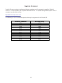
SAMPLE GGA MESSAGE STRUCTURE
The following example of the GGA message shows the format typical of NMEA messages.
$GPGGA,171741,3019.3909,N,09741.8629,W,2,08,00.9,+00180,M,x.x,M,003,0800*78
Field 1
Field 2
Field 3
Field 4
Field 5
Type of Message Field 6
Field 7
Message Source (GPS) Field 8
Field 9
Message Flag Field 10
Field 11
Field 12
Field 13
Field Description Field Description
$ Message Flag 6 Horizontal Dilution of Precision
GP Message Source (GPS) 7 Antenna Altitude Ref: Mean Sea
Level (geoid)
GGA Type of Message 8 Units of Antenna Altitude
(meters in example)
1 Universal time coordinate (UTC) 9 Geoidal Separation
of Position
2 Latitude, North or South 10 Units of Geoidal Separation
(meters in example)
3 Longitude, East or West 11 Age of Differential Data, seconds
4 GPS Quality Indicator (mode) 12 Reference Station ID
5 Number of Satellites in Use 13 Checksum

10
Starlink Protocol
Control of Raven receivers is performed using a proprietary set of commands named the “Starlink
Protocol”. These commands are compliant with NMEA 0183. A complete listing and description of each
command may be obtained from
http://www.ravenprecision.com.
The following is a list of commands/queries that may be supported in the Phoenix 50.
Receiver Command Receiver Query
DIF DIF
NME GPSID
PBM NME
PTA PAR
PTB PBM
RKC PTA
RST PTB
SAV RID
SLI RKC
SPD SLI
W1M W1S


Raven Industries will not assume any expense or liability for repairs
made outside our facilities without written consent. Raven Industries
is not responsible for damage to any associated equipment or
products and will not be liable for loss of profit or other special
damages. The obligation of this warranty is in lieu of all other
warranties, expressed or implied, and no person or organization is
authorized to assume any liability for Raven Industries.
Damages caused by normal wear and tear, misuse, abuse, neglect,
accident, or improper installation and maintenance are not covered
by this warranty.
What Does this Warranty Cover?
How Long is the Coverage Period?
How Can I Get Service?
What Will Raven Industries Do?
What is not Covered by this Warranty?
Bring the defective part and proof of purchase to your Raven Dealer.
If your Dealer agrees with the warranty claim, the Dealer will send the
part and proof of purchase to their distributor or to Raven Industries
for final approval.
Upon confirmation of the warranty claim, Raven Industries will, at our
discretion, repair or replace the defective part and pay for return
freight.
RAVEN INDUSTRIES
Limited Warranty
This warranty covers all defects in workmanship or materials in your
Raven Applied Technology Product under normal use, maintenance,
and service.
Raven Applied Technology Products are covered by this warranty for
12 months after the date of purchase. This warranty coverage applies
only to the original owner and is nontransferable.
-
 1
1
-
 2
2
-
 3
3
-
 4
4
-
 5
5
-
 6
6
-
 7
7
-
 8
8
-
 9
9
-
 10
10
-
 11
11
-
 12
12
-
 13
13
-
 14
14
-
 15
15


Raven Phoenix 50 Installation & Operator's Manual
- Category
- GPS receiver modules
- Type
- Installation & Operator's Manual
Ask a question and I''ll find the answer in the document
Finding information in a document is now easier with AI
Related papers
-
Raven INVICTA 115 User manual
-
-
-
-
Smithco Envizio Pro II Operating instructions
-
-
-
-
-
Other documents
-
 TRIMBLE AgGPS 252 Receiver User manual
-
 Trimble Outdoors AgGPS 252 User manual
-
 Trimble Outdoors 132 User manual
-
CSI POWERMAX Reference guide
-
Simrad MX521/MX521A/MX521B DGPS Sensor Operating instructions
-
 Ag Leader Technology GPS 1500 User manual
-
Furuno SC-110 User manual
-
-
Garmin GPS 19x HVS (NMEA 0183) Owner's manual
-
 versa ag leader User manual


