ST AN5691 ASM330LHBxx-ASILB-Library User manual
- Type
- User manual

Introduction
This application note provides guidelines and recommendations for the proper use of the safety software library
(ASM330LHBxx_ASILB_library) referred to as "safety engine" throughout this document. This library is used in target ASIL-B
applications that need information about the linear accelerations and angular rates of the vehicle, like in-dash car navigation,
accurate positioning, V2X (vehicle-to-everything), radar, lidar, and camera stabilization systems or others.
More specifically, the safety engine is intended as a Safety Element out of Context (SEooC) and it is developed according to
ISO26262-6.
The notation ASM330LHBxx refers to the IMU sensors with product names ASM330LHB and ASM330LHBG1, and it is used to
reference both devices.
This application note clarifies how safety boundaries and behavior have been conceived, and how the entire safety flow has
been followed from the assumed item to the SEooC software safety requirements, available and strictly related to the proposed
SEooC architecture (refer to Section 1.1 SEooC architecture), not including all other components, PCB design and layout of
traces, vias and ground plane.
To allow an analysis of the safety engine capability to reach the required safety level, assumptions have been made, following
the concept of SEooC described in the ISO26262.
ASM330LHBxx_ASILB_library safety manual
AN5691
Application note
AN5691 - Rev 5 - February 2023
For further information contact your local STMicroelectronics sales office.
www.st.com

1SEooC overview
1.1 SEooC architecture
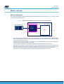
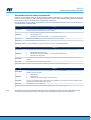
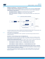
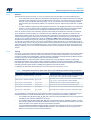
The system block diagram where the safety engine is developed as an SEooC is shown in Figure 1 and it is made
up of the following building blocks.
Figure 1. System block diagram in which the SEooC has been developed
Host processor
SMU
Safety
Engine
2x ASM330LHBxx
SEooC (Safety Engine)
• Two identical sensors (redundancy of IMUs), properly supplied, provide information to the system about the
linear acceleration along the axes of the module where the sensors are mounted, hence of the car, and the
angular rate of the axes of the car.
• A host processor, properly supplied, is connected to a subsequent elaboration path and it has an interface
suitable for the communication with the two IMUs.
• A communication bus allows communication between the host processor and the two IMUs.
• The safety engine running on the host processor, which communicates with the two IMUs through the host
processor communication interface and which includes the drivers for the correct use of the two IMUs. The
safety engine embeds the safety mechanisms designed to meet the technical safety requirements.
• The output of the safety engine, which is the input of the SMU inside the host processor.
AN5691
SEooC overview
AN5691 - Rev 5 page 2/28

1.2 Basic assumptions
The safety engine has been developed based on the following assumptions:
Assumption #1: It is assumed that the system in which the SEooC is included requires that the SEooC itself is a
safety level of ASIL-B.
Assumption #2: It is assumed that the integration of the software into the MCU, or application specific processor,
meets the requirements given in Section 2.5.2 Software freedom from interference.
Assumption #3: It is assumed that the architecture of the SEooC, described in this document, will not be
modified or compromised in the application.
Assumption #4: It is assumed that the customer's design, using the safety engine, fulfills specific safety manual
(SM) assumptions and requirements. If the customer’s design does not fully comply with the assumptions, the
customer must show an alternative solution similarly efficient concerning the safety requirements.
Assumption #5: It is assumed that the component does not compromise the operating conditions of the safety
engine, if any component is interposed between the IMUs and the safety engine in the host processor.
Assumption #6: It is assumed that all relevant safety mechanisms are enabled and configured according to the
information reported in this document.
Assumption #7: It is assumed that electronic control unit network environments (refer to Table 13 of ISO
26262-6:2018,11.4.1) are not considered when verifying that the embedded software fulfills the software safety
requirements in the target environment. The execution of these tests is left to the system integrator to ensure
coherency to the overall concept.
Assumption #8: It is assumed that the safety engine works with two identical IMUs, called ASM330LHBxx.
Assumption #9: It is assumed that the system integrator verifies the compliancy of ASM330LHBxx with
ISO26262-5, by evaluating the hardware according to ISO 26262-8:2018(E) clause 13 as a class II component off
the shelf and knowing that ASM330LHBxx is a hardware element not developed according to ISO26262.
Assumption #10: It is assumed that independently from the specific item, IMUs ASM330LHBxx are primarily
adopted to provide the measurements of acceleration and angular rates to vehicle electronic control units.
Assumption #11: It is assumed that the IMUs are exposed to the same environmental and operational conditions
they are intended for, according to what is stated in the datasheet.
AN5691
Basic assumptions
AN5691 - Rev 5 page 3/28

2Safety concept
In this section, the safety analysis at vehicle level is assumed, based on the result typically created by the OEM
and partially provided to a supplier. Malfunctions and hazards are reported in the assumed HARA analysis, for
which a global ASIL (B) evaluation is available.
The following outcome relates to the generic item considered, acting at system level (vehicle) independently from
any other host source input.
Note: In the safety concept, the actions of the driver are not part of the system inputs, which means that the
driver is not included as part of the functional safety concept. As a consequence:
•Reaction of the user in warning indications is not considered.
•Possibility of function override by the driver is not applicable.
2.1 Assumed safety goals
The following hazards and attributes are identified as the output of an assumed hazard and risk assessment,
related to the SEooC architecture shown in Figure 1.
Assumption #12: It is assumed that the HARA at vehicle level is already produced by the system integrator.
Safety goals and safe states are defined at item level for the specific item in which the SEooC is included. At the
boundary of the SEooC, safety goals are assumed, considering a portion of the system (shown in Figure 1) to be
integrated in the overall item at vehicle level, and are defined here for functional purposes, with assumed inherited
ASIL evaluation and DTTI.
Note: The “diagnostic test time interval” (DTTI) is used instead of “fault tolerance time interval” (FTTI) at this level
of hierarchy because part of the whole FTTI budget for failure notification at system level could include other
activities, which might also require some time to be performed.
Diagnostic test time: 100 ms. It is assumed that the end user of the IMU verifies the compliancy of such limit to
the final application.
Assumption #13: It is assumed that:
•Safety goal: To prevent that information relative to acceleration and angular rate are passed as inaccurate
or are not passed to the following modules of the elaboration chain.
•Safe state: The safety engine shall identify occurrences of IMU faults and alert the system hosting the
library with a flag/alarm mechanism.
•Diagnostic test time: 100 ms. It is assumed that the system integrator verifies the compliancy of such limit
to the final application.
AN5691
Safety concept
AN5691 - Rev 5 page 4/28

2.2 Failure mode analysis
The following malfunction related to the safety engine is identified:
•MF01: Failure of the safety engine
Output is corrupted, degraded, or absent.
Assumption #14: It is assumed that, corresponding to the assumed safety goal and the preliminary architecture
depicted in Figure 1, the following set of malfunctions and failures are valid:
•MF02: Failure of the communication interface
SPI/I²C communication is corrupted or absent, ports are defective, or a high rate of packet loss is verified.
•MF03: Failure of the power supply
Power supply is absent, or it is not stable.
•MF04: Failure of the IMU raw measurement
The safety engine cannot process raw data because absent or corrupted.
Based on the considerations proposed so far, it is assumed that the SEooC safety goal can be allocated as a
single top-level requirement defined as below.
ID SR_01
Description The safety engine shall always provide a reliable and accurate measurement of acceleration and angular rates
from the IMUs. Otherwise, it notifies through an error code.
Safe state Notification at the output of the safety engine
DTTI 100 ms
The assumed safe state is the notification at the boundary of the SEooC, meaning that the final target of
the integrated software module is for diagnostics/monitoring duties. Failure avoidance mechanisms are not
considered.
Assumption #15: It is assumed that reactions to error flags raised by the library are managed at integration level
and that the output data of the library, in the presence of an error flag, is not considered as valid data.
AN5691
Failure mode analysis
AN5691 - Rev 5 page 5/28

2.3 Assumed functional safety requirements
Based on the information relative to the SEooC safety goals and safe states, it is possible to derive the functional
safety concept. Its target is to define the appropriate safety functions able to fulfill the safety goals and to allocate
these safety functions to the elements of the preliminary architecture.
The results in the functional safety requirements and the functional safety architecture that can be derived from it
are indicated in the following tables.
ID FSR_01
Description The safety engine integrated in the host processor shall receive (that is, data is present) input data from
the IMU subsystem. Communication shall be verified.
TSR items
1. SPI/I²C interface check (communication and packet loss)
2. Port electrical check
3. IMU detection and data availability → for example, WHOAMI check
Motivation Continuous availability of input data from both IMUs shall be verified.
Safe state Fault indication and/or invalid data
Validation criteria It shall be validated by specific validation test cases on the embedded platform.
ID FSR_02
Description The safety engine shall always provide input data to the SMU integrated in the host processor.
TSR items
1. Datasheet specification check
2. IMU detection and data availability → for example, WHOAMI check
3. Software block diagnostics
Motivation The correct functioning of systems using the IMU depends on the accurate input data from the IMU
modules.
Safe state Fault indication and/or degraded output data
Validation criteria It shall be validated by specific validation test cases on the embedded platform.
ID FSR_03
Description The safety engine integrated in the host processor shall receive RELIABLE input data from the IMU. This
reliability has to be checked.
TSR items
1. Data integrity
2. Data accuracy
3. Information about data integrity and data accuracy
Motivation Accuracy of the safety engine output relies on the availability of accurate and correct input data from IMU
modules, with guarantee of the accuracy level.
Safe state Fault indication with specific FLAG
Validation criteria It shall be validated by specific validation test cases on the embedded platform.
Note: RELIABLE input data are intended as data that respect datasheet parameters and also that represent proper
device functionality (expected output of the motion sensor submitted to certain stimulus conditions).
AN5691
Assumed functional safety requirements
AN5691 - Rev 5 page 6/28

2.4 Assumed technical safety concept
The technical safety concept relies on the inputs derived from the functional safety requirements and the
assumptions of the preliminary architecture. Safety mechanisms are defined as well as the technical safety
requirements.
Based on the listed FSR requirements and the inputs from selected customers, the following technical safety
requirements (TSR) are assumed. At this level, it is possible to identify the specific requirement related to the
software domain, explicitly derived from TSR IDs.
ID TSR_01_01_SW
Description The safety engine shall check the presence of an IMU subsystem.
Safe state Fault indication and/or invalid data
ASIL BFTT 100 ms Status Accepted
ID TSR_03_01_SW
Description The safety engine shall return verified data to the SMU integrated in the host processor.
Safe state Fault indication with specific FLAG
ASIL BFTT 100 ms Status Accepted
ID TSR_04_01_SW
Description The safety engine shall check the integrity of input data from the IMU subsystem.
Safe state Fault indication
ASIL BFTT 100 ms Status Accepted
ID TSR_04_02_SW
Description The safety engine shall check the accuracy of input data from the IMU subsystem.
Safe state Fault indication
ASIL BFTT 100 ms Status Accepted
ID TSR_04_03_SW
Description The safety engine shall return an informative measure on the reliability and accuracy of the IMU subsystem
input data.
Safe state Fault indication
ASIL BFTT 100 ms Status Accepted
Assumption #16: It is assumed that the following technical safety requirements concerning the hardware part
are assumed and shall be validated by specific test cases accepted by the system integrator for the specific
embedded architecture:
ID TSR_01_01_HW
Description The SPI/I²C interface must be validated in terms of overall functionality and packet loss rate.
Safe state Fault indication and/or invalid data
ASIL BFTT 100 ms
AN5691
Assumed technical safety concept
AN5691 - Rev 5 page 7/28

ID TSR_01_02_HW
Description The SPI/I²C ports and pins must be verified.
Safe state Fault indication and/or invalid data
ASIL BFTT 100 ms
ID TSR_02_01_HW
Description Vdd and Vdd/IO lines shall guarantee the correct power supply voltage to the IMU subsystem.
Safe state Fault indication and/or invalid data
ASIL BFTT 100 ms
ID TSR_02_02_HW
Description Vdd and Vdd/IO ports must be verified.
Safe state Fault indication and/or invalid data
ASIL BFTT 100 ms
2.4.1 Allocation of safety requirements
In relation to the FSR/TSR trace, the following table lists the hierarchical reference.
FSR ID TSR ID
FSR_01 TSR_01_01_SW
FSR_02 TSR_03_01_SW
FSR_03
TSR_04_01_SW
TSR_04_02_SW
TSR_04_03_SW
AN5691
Assumed technical safety concept
AN5691 - Rev 5 page 8/28

2.5 Avoidance of systematic failures
Software is developed compliant to ISO2626-part6 in order to minimize the occurrence of systematic failures. In
particular, the activities, the documentation flow, and the life cycle of the products are fully managed, ensuring that
processes, people, and tools are properly managed according to the ISO specification.
2.5.1 Software failure modes and ISO coding guidelines
The library has been developed, taking into account the software failure modes through the safety analysis
produced. The minimization of fault propagation at software level is pursued with the exploitation of coding
guidelines defined in accordance with ASIL-B requirements. An extract of these rules is indicated in the following
table.
Table 1. Extract of coding guidelines
ID Description
Safe_code_X One entry and one exit point in all functions
Safe_code_Y Restricted use of pointers
Safe_code_Z No implicit type conversion
Safe_code_XX No recursion
Safe_code_YY MISRA_C coding rules
Safe_code_ZZ McCabe number < TH for each single module
During software development, safety analyses and verifications have been produced:
• SW-DFA (FFI) and generated assumptions for safety integration
• SW-HAZOP and SW-FMEA at the architecture/design level
• Static code analysis at unit design / code implementation level
• Dynamic code coverage at testing level
2.5.2 Software freedom from interference
Software has been evaluated and analyzed in relation to the interference failure modes, associated to the library
integration in the host processor. These failure modes include:
•Code failures: faulty software modifies executable code.
•Data failures: faulty software or falsely configured bus masters (DMA) could write to variables, parameters,
heaps, and stacks.
•Hardware resource: faulty software or falsely configured bus masters (DMA) could write to configuration
registers and hardware devices.
•Program control flow: faulty software modifies the sequence of other safety software, for example,
corrupting interrupt vectors, TCB, stack, missing restore of registers and flags.
•Time: faulty software influences the correct timing of safety software, for example, by blocking resources,
high frequency of context switches and soft-interrupts.
Software safety mechanisms to cope with these failures have been included, and additional assumptions are
derived for the system integrator because at library level any possible control/avoidance measure has been
evaluated as unachievable.
AN5691
Avoidance of systematic failures
AN5691 - Rev 5 page 9/28

2.6 Random failure modes and safety mechanisms
Starting from the list of malfunctions, it is possible to refine the group of failure modes associated to the
ASM330LHBxx sensor. Contributions to this refinement include inputs from different customers and internal
analysis.
Based on the derived safety goals, failure modes can generate three groups of hazards (H1, H2, H3): data
availability, data integrity, and data accuracy. For each of these groups, faults are listed:
•H1. Data availability
–Data loss, communication interface fault
–Deviation in actual sample rate with respect to the set
–Uncontrolled reset
•H2. Data integrity
–Register corruption
–Stuck and quasi-stuck output
•H3. Data accuracy
–Full-scale fault
–Bias/ZRL out of spec
–Pulse transitions
–Redundancy
For the sake of clarity, let’s introduce additional assumptions:
Assumption #17: It is assumed that the system where the SEooC is included has the capability of reading the
output of the safety engine.
Assumption #18: It is assumed that the list of implemented safety requirements and safety mechanisms covers
all the identified failures for the system under consideration. Moreover, communication failures are in part
requested by the host, so that, in this regard, the loss of communication and message corruption is analyzed.
AN5691
Random failure modes and safety mechanisms
AN5691 - Rev 5 page 10/28

3Software development
This section provides details on the software requirements and associated safety mechanisms implemented
within the safety library as well as detailed information on faults covered.
The list of top-level software requirements is summarized in Table 2. SEooC high-level software safety
requirements, low level requirements are derived from splitting each of the entries in requirements addressing
each specific failure mode that should be covered by a dedicated safety mechanism. In this sense, it is clear
from a functional perspective the equivalence between low-level software requirements and software safety
mechanisms. The entire list of software requirements inherits the same ASIL per the discussions provided above
within FSC and TSC. The alignment with the ISO26262 and QMS processes is then approached to ensure overall
ASIL-B compliancy.
Table 2. SEooC high-level software safety requirements
SEooC safety
requirement
ID
SEooC safety requirement TSR reference SEooC functionality
SW_REQ_01
IMU information is present and
verified by the safety engine
[presence]
TSR_01_01_SW
The safety engine shall check the availability of data
from the IMUs and alert if the connection is lost or the
data is missing. This can be verified with:
• WHOAMI check
• Safe read/write
• Refresh of registers
SW_REQ_02
Data from IMU shall be correct
and in line with the datasheet,
at the startup of the system
[integrity]
TSR_04_01_SW
The safety engine shall verify the integrity of input data
from the IMU at startup. Integrity can be verified based
on:
• Output data register checks
• Control register checks
• OTP registers
• Data checks during stationary conditions
SW_REQ_03
Data from IMU shall be
continuously verified in terms
of integrity and correctness
during normal operations
[integrity]
TSR_04_01_SW
The safety engine shall verify continuously that the
integrity of input data from the IMU is corrupted or not.
Integrity can be verified based on:
• Output register checks
• Control register checks
• ODR checks
SW_REQ_04
Data from IMU shall be
verified in terms of accuracy
and alignment with datasheet
boundaries
[accuracy]
TSR_04_02_SW
The safety engine shall check the accuracy of the
input data from the IMUs, relating in particular on the
evolution over time of:
• Sensor bias and norm
• Sensitivity variations
• Data stuck and quasi-stuck
• Cross-correlation between sensors data
SW_REQ_05
Software diagnostics shall be
guaranteed and provided at
the input of the SMU
[diagnostic]
TSR_03_01_SW
TSR_04_03_SW
The safety engine shall run the overall diagnostic in
order to guarantee explicit information at the output.
Any failure at diagnostic level must be avoided:
• Safe coding
• ISO guidelines
Note: The integrity and accuracy of the input data can be only checked and not retrieved in case of failures.
AN5691
Software development
AN5691 - Rev 5 page 11/28

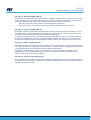
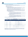
3.1 Software architecture – low-level requirements
The defined software architecture is illustrated in Figure 2. Preliminary software architecture, where it is shown
the diagnostic and alarm function block able to expose at the output an error code mechanism aligned with the
data provided by the sensors. With reference to this architecture, the list of low-level software requirements /
safety mechanisms is distinguished in:
•[ISC safety mechanisms - integrity] run at startup during BOOT and system offline.
•[IRC safety mechanisms - integrity] run at runtime during normal operation.
•[ARC safety mechanisms - accuracy] run at runtime during normal operation, also exploiting sensor
redundancy.
Figure 2. Preliminary software architecture
The system integrator should confirm the adequacy of the mechanisms provided, within the resulting failure mode
coverage, by the software library in the context of the specific system level analysis.
3.1.1 Initial checks and configuration
To ensure the absence of latent faults, a series of operations are processed during boot while the device is
stationary after reset.
[ISC_SM_01 – Accelerometer/gyroscope self-test][SW_REQ_02]
When the accelerometer self-test is enabled, an actuation force is applied to the sensor, simulating a defined
input acceleration. In this case, the sensor outputs exhibit a change in their DC levels, which are related to the
selected full-scale through the sensitivity value.
At startup, with the vehicle stationary and engine off, the library is able to perform in cascade the accelerometer
and gyroscope self-test procedures with an alternate scheme for the two sensors as follows:
• Self-test applied on 5 samples of XL_IMU_1 + contextual stationary check on IMU_2
• Self-test applied on 5 samples of XL_IMU_2 + contextual stationary check on IMU_1
• Self-test applied on 5 samples of GYRO_IMU_1 + contextual stationary check on IMU_2
• Self-test applied on 5 samples of GYRO_IMU_2 + contextual stationary check on IMU_1
To perform this mechanism, the library configures the accelerometer sensors at 52 Hz with FS = ± 4 g and the
gyroscope sensors at 52 Hz with FS = ± 2000 dps. The thresholds used by the library to evaluate a stationary
state are 30 LSB for the accelerometer, 5 LSB for the gyroscope, while the thresholds to evaluate the self-tests
are the low and high limits indicated in the datasheet.
If the condition on the stationary check fails, a specific error code is provided as ERR_ST_ACC_NOT_STILL.
In the case of verified stationary condition but failing self-test output, the specific error code is generated as
ERR_ST_ACC_FAIL.
AN5691
Software architecture – low-level requirements
AN5691 - Rev 5 page 12/28

[ISC_SM_02 – IMU STATUS][SW_REQ_01]
At startup, with the vehicle stationary and the engine off, the library is able to perform a check on the connected
device along with its ID and the OTP correct loading, in turn used to confirm the correct BOOT procedure. Both
checks are implemented with a safe-read function and the return value therein implemented:
• ERR_DEV_ID in case of NULL return from the WHOAMI safe_read function.
• ERR_BOOT_FAIL in case of NULL return from the STATUS REGISTER safe_read function.
[ISC_SM_03 – XLnorm_init][SW_REQ_02]
Data buffers derived from the accelerometer self-test procedure can be used at startup to evaluate the norm of
the accelerometer. The contextual check for IMU stationary condition is used to validate the comparison of the
computed norm with a threshold derived from the datasheet specifications.
In particular, if the absolute value of the difference between the smoothed norm and 1.0 g exceeds a threshold
(0.319808 g for ASM330LHB, 0.406411 g for ASM330LHBG1), the ERR_ACC_BIAS error is generated and
returned. This threshold is based on the datasheet parameters called LA_Off long term and LA_So% long term.
[ISC_SM_04 – GBias_init][SW_REQ_02]
Data buffers derived from the gyroscope self-test procedure can be used at startup to evaluate the bias on each
axis of the gyroscope. The contextual check for IMU stationary condition is used to validate the comparison of the
computed biases with the thresholds derived from the datasheet specifications.
In particular, if the absolute value of any of the smoothed gyroscope axes exceeds a threshold (7 dps for
ASM330LHB, 10 dps for ASM330LHBG1, refer to the G_Off - long term parameter in the datasheet), the
ERR_GYR_BIAS error is generated and returned
[ISC_SM_05 – Params Check] [SW_REQ_02]
The configuration structure filled in by the user is verified through plausibility checks and min-max ranges aligned
with expected values. In the case of verified values outside the expected range, the ERR_PARAM error code is
provided in the diagnostic output.
AN5691
Software architecture – low-level requirements
AN5691 - Rev 5 page 13/28

3.1.2 Runtime integrity checks
Data integrity can be verified at runtime by evaluating the output data registers and their refresh rate, along with
detecting communication issues.
[IRC_SM/INT_02 – Clock/ODR monitoring][SW_REQ_03]
If the INT mode is enabled, the library implements a dedicated check on the refresh rate of the incoming data.
The GDA and XLDA bits of STATUS REG (1Eh) are used. In the case of missing refresh data or a DTIME outside
the range specified in the configuration sensor register, the error codes are provided as ERR_DATA_READY and
ERR_DTIME.
[IRC_SM_03 – CTRL registers monitoring][SW_REQ_03]
At runtime, it is possible to evaluate any undesired changes of sensor configurations and validate the integrity
of the associated registers. This can be done with the continuous dump of the CTRL registers during normal
operation. This is done within FTT constraints and the related error code ERR_CTRL is provided in case of
unintended registers access/change.
[IRC_SM_04 – COMM diagnostic][SW_REQ_03]
At runtime, after the init check for IMU STATUS with the mechanism [ISC_SM_02], the library is able to perform a
detection of any kind of communication loss including accelerometer/gyroscope sensor data loss. In this case, the
failure is considered as not permanent if a connection or data presence is re-established during data processing.
The library provides within the same FTT the error code ERR_COMM in this case.
[IRC_SM_05 – Stuck monitoring][SW_REQ_03]
The library implements an algorithm to evaluate if the signal of both the IMUs results in being stuck at a value.
Detection of the stuck signal is based on a defined number of samples, and a counter for how many samples are
replicated for all the sensor axes at the same time and a specific error code ERR_STUCK is provided from the
library within FTT.
[IRC_SM_06 – RESET][SW_REQ_03]
An unexpected/undesired hard reset of the sensors for both the IMUs is detected by the library with a defined
compare of control registers at runtime. Any unexpected reset results in the loading of the default configuration,
and the ERR_RESET code is provided from the library.
[IRC_SM_07 – SRC][SW_REQ_03]
If enabled by the user through the src_en flag parameter, the library implements a CRC-like mechanism with
multiple reads of the same data. In the case of inconsistency of read data, the ERR_SRC error flag is provided at
the output of the diagnostic output.
AN5691
Software architecture – low-level requirements
AN5691 - Rev 5 page 14/28

3.1.3 Runtime accuracy checks
Data accuracy refers to the capability of the IMU to provide data that are correlated with the physical inputs
(acceleration and angular speed) as described in the datasheet specifications.
[ARC_SM_01 – FS out of range][SW_REQ_04]
At runtime, the library is able to detect if the output of the IMUs has reached the saturation value or even more in
relation to the set FS parameter (saturation value inside the library is set equal to 32764 LSB). In this case, the
ERR_ACC_SAT/ERR_GYR_SAT error codes are provided.
[ARC_SM_02 – BIAS monitoring][SW_REQ_04]
At runtime, for both the IMUs, an evaluation of the bias for both the accelerometer and gyroscope is performed. In
this case, because the validity of the computed output depends on the knowledge of the stationary condition, an
input is required in order to trigger the algorithm chain. In particular, a binary flag steady/not steady is mandatory
to validate the output and the possible fault detection with the ERR_BIAS error codes.
[ARC_SM_03 – Q-Stuck monitoring][SW_REQ_04]
At runtime, the library is able to detect if the two IMUs present a signal defined as quasi-stuck, meaning that the
output is stuck at a constant value with small oscillations around this value.
[ARC_SM_04 – Pulse transition][SW_REQ_04]
At runtime, the accelerometer and gyroscope signals of both the IMUs is verified in relation to the presence of
single and repetitive spikes.
[ARC_SM_05 – Redundancy][SW_REQ_04]
The redundancy mechanism is used to evaluate the deviation on the output of both the accelerometer
and gyroscope with an RMSE metric applied to a buffer of N samples considering a time window of 100
ms. If the computed RMSE value is above the defined threshold, the error code ERR_ACC_REDUNDANCY/
ERR_GYR_REDUNDANCY is provided. Within this mechanism, it is possible to provide information relative to
sensitivity faults in one of the IMUs and, in general, a fault in the sensing chain.
[COD – Coding][SW_REQ_05]
The library is developed according to the guidelines of ASIL-B compliancy in order to guarantee minimization
or absence of systematic failures that can influence the correct capability of generating the required diagnostic
output.
Note also that in accordance with the [ARC_SM_02 – BIAS monitoring] mechanism, the biases of the
accelerometer and gyroscope sensor cannot be evaluated while the vehicle is moving. This generated the
following assumption.
Assumption #19: It is assumed that a required input of the library is a flag for a stationary vehicle. If the vehicle is
stationary, the bias check mechanisms are active, otherwise they are automatically disabled.
The following table provides an example of the list of error codes with description and output mask.
AN5691
Software architecture – low-level requirements
AN5691 - Rev 5 page 15/28

Table 3. Sample error codes
Error Code Mask Description
ERR_NONE 0x0000000000000000ULL No error
ERR_COMM_0 0x0000000000000001ULL Communication error (imu id = 0)
ERR_READ_BACK_0 0x0000000000000002ULL Read back error (imu id = 0)
ERR_DEV_ID_0 0x0000000000000004ULL Device ID check error (imu id = 0)
ERR_BOOT_FAIL_0 0x0000000000000008ULL Device boot error (imu id = 0)
ERR_ST_ACC_FAIL_0 0x0000000000000010ULL Accelerometer self-test failed (imu id = 0)
ERR_ST_GYR_FAIL_0 0x0000000000000020ULL Gyroscope self-test failed (imu id = 0)
ERR_ST_ACC_NOT_STILL_0 0x0000000000000040ULL Accelerometer not stationary during self-test (imu id = 0)
ERR_ST_GYR_NOT_STILL_0 0x0000000000000080ULL Gyroscope not stationary during self-test (imu id = 0)
ERR_CTRL_REG_0 0x0000000000000100ULL Device configuration integrity error (imu id = 0)
ERR_RESET_0 0x0000000000000200ULL Device unexpected reset error (imu id = 0)
ERR_ACC_SAT_0 0x0000000000000400ULL Accelerometer saturation error (imu id = 0)
ERR_GYR_SAT_0 0x0000000000000800ULL Gyroscope saturation error (imu id = 0)
ERR_ACC_STUCK_0 0x0000000000001000ULL Accelerometer is stuck (imu id = 0)
ERR_GYR_STUCK_0 0x0000000000002000ULL Gyroscope is stuck (imu id = 0)
ERR_ACC_PULSE_0 0x0000000000004000ULL Accelerometer pulse error (imu id = 0)
ERR_GYR_PULSE_0 0x0000000000008000ULL Gyroscope pulse error (imu id = 0)
ERR_ACC_BIAS_0 0x0000000000010000ULL Accelerometer bias error (imu id = 0)
ERR_GYR_BIAS_0 0x0000000000020000ULL Gyroscope bias error (imu id = 0)
ERR_ACC_QUASI_STUCK_0 0x0000000000040000ULL Accelerometer quasi stuck error (imu id = 0)
ERR_GYR_QUASI_STUCK_0 0x0000000000080000ULL Gyroscope quasi stuck error (imu id = 0)
ERR_SRC_0 0x0000000000100000ULL Sample redundancy check error (imu id = 0)
ERR_COMM_1 (ERR_COMM_0 << 32ULL) Communication error (imu id = 1)
ERR_READ_BACK_1 (ERR_READ_BACK_0 << 32ULL) Read back error (imu id = 1)
ERR_DEV_ID_1 (ERR_DEV_ID_0 << 32ULL) Device ID check error (imu id = 1)
ERR_BOOT_FAIL_1 (ERR_BOOT_FAIL_0 << 32ULL) Device boot error (imu id = 1)
ERR_ST_ACC_FAIL_1 (ERR_ST_ACC_FAIL_0 << 32ULL) Accelerometer self-test failed (imu id = 1)
ERR_ST_GYR_FAIL_1 (ERR_ST_GYR_FAIL_0 << 32ULL) Gyroscope self-test failed (imu id = 1)
ERR_ST_ACC_NOT_STILL_1 (ERR_ST_ACC_NOT_STILL_0 << 32ULL) Accelerometer not stationary during self-test (imu id = 1)
ERR_ST_GYR_NOT_STILL_1 (ERR_ST_GYR_NOT_STILL_0 << 32ULL) Gyroscope not stationary during self-test (imu id = 1)
ERR_CTRL_REG_1 (ERR_CTRL_REG_0 << 32ULL) Device configuration integrity error (imu id = 1)
ERR_RESET_1 (ERR_RESET_0 << 32ULL) Device unexpected reset error (imu id = 1)
ERR_ACC_SAT_1 (ERR_ACC_SAT_0 << 32ULL) Accelerometer saturation error (imu id = 1)
ERR_GYR_SAT_1 (ERR_GYR_SAT_0 << 32ULL) Gyroscope saturation error (imu id = 1)
ERR_ACC_STUCK_1 (ERR_ACC_STUCK_0 << 32ULL) Accelerometer is stuck (imu id = 1)
ERR_GYR_STUCK_1 (ERR_GYR_STUCK_0 << 32ULL) Gyroscope is stuck (imu id = 1)
ERR_ACC_PULSE_1 (ERR_ACC_PULSE_0 << 32ULL) Accelerometer pulse error (imu id = 1)
ERR_GYR_PULSE_1 (ERR_GYR_PULSE_0 << 32ULL) Gyroscope pulse error (imu id = 1)
ERR_ACC_BIAS_1 (ERR_ACC_BIAS_0 << 32ULL) Accelerometer bias error (imu id = 1)
ERR_GYR_BIAS_1 (ERR_GYR_BIAS_0 << 32ULL) Gyroscope bias error (imu id = 1)
AN5691
Software architecture – low-level requirements
AN5691 - Rev 5 page 16/28

Error Code Mask Description
ERR_ACC_QUASI_STUCK_1 (ERR_ACC_QUASI_STUCK_0 << 32ULL) Accelerometer quasi stuck error (imu id = 1)
ERR_GYR_QUASI_STUCK_1 (ERR_GYR_QUASI_STUCK_0 << 32ULL) Gyroscope quasi stuck error (imu id = 1)
ERR_SRC_1 (ERR_SRC_0 << 32ULL) Sample redundancy check error (imu id = 1)
ERR_TIMEOUT 0x0400000000000000ULL Data-ready polling timeout error
ERR_DATA_READY 0x0800000000000000ULL Data-ready not updated error
ERR_DTIME 0x1000000000000000ULL Delta-time error
ERR_PARAM 0x2000000000000000ULL Invalid parameter error
ERR_ACC_REDUNDANCY 0x4000000000000000ULL Accelerometer redundancy error
ERR_GYR_REDUNDANCY 0x8000000000000000ULL Gyroscope redundancy error
AN5691
Software architecture – low-level requirements
AN5691 - Rev 5 page 17/28

3.2 Enabling safety mechanisms and software APIs
The compiled library assures compliancy to the ASIL-B safety level with the whole set of the implemented safety
mechanisms. This means that the user cannot disable a subset of these features or choose one that is the most
suitable for his purposes.
The library is shared in binary format along with its header file. The exported APIs and the library parameters are
included. Each API returns an integer containing the error code.
3.2.1 Initialization
The library is initialized by calling the ab_init function. It takes as input a structure with the configuration to be set
in the library. All the configuration parameters must be set before calling the ab_init function.
The structure containing the configuration parameters is shown below.
/**
*@brief Library configurati on data structure.
*@details Contain the library parameters that can be configured.
*/
struct ab {
uint8_t device;/**< @brief Device code.*/
uint8_t interface;/**< @brief Interface code. */
uint8_t odr;/**< @brief Output data rate code. */
uint8_t acc_fs;/**< @brief Accelerometer full-scale code. */
uint8_t gyr_fs;/**< @brief Gyroscope full-scale code. */
uint8_t int_pin;/**< @brief Interrupt pin configurati on code. */
float tim_freq; /**< @brief Timer frequency [Hz]. */
int16_t rot0[3][3]; /**< @brief Rotation matrix to be applied to primary sensor data (imu id = 0). */
int16_t rot1[3][3]; /**< @brief Rotation matrix to be applied to secondary sensor data (imu id = 1). */
float acc_red_ths;/**< @brief Accelerometer redundancy threshold [g]. */
float gyr_red_ths;/**< @brief Gyroscope redundancy threshold [dps]. */
float acc_pul_ths;/**< @brief Accelerometer pulse threshold [g]. */
float gyr_pul_ths;/**< @brief Gyroscope pulse threshold [dps]. */
float acc_qs_ths;/**< @brief Accelerometer quasi stuck threshold [g]. */
float gyr_qs_ths;/**< @brief Gyroscope quasi stuck threshold [dps]. */
uint8_t src_en;/**< @brief Sample redundancy check enable. */
uint8_t poll_dis;/**< @brief Data-ready polling disable during devices check-up. */
uint64_t (*write)(uint8_t id,uint8_t addr,uint8_t val); /**< @brief Function pointer for writing data to devices. */
uint64_t (*read)(uint8_t id, uint8_t addr,uint8_t *val,uint16_t len); /**< @brief Function pointer for reading data from devices. */
uint32_t (*systick)(void); /**< @brief Function pointer for getti ng system ti ck [ms]. */
void (*delay)(uint32_t delay); /**< @brief Function pointer for generati ng a delay [ms]. */
};
A brief description of them is as follows:
•device: device configuration. It can be set to ASM330LHB or ASM330LHBG1.
•interface: interface configuration. It can be set to I²C, MIPI I3CTM, SPI 3-wire, or SPI 4-wire.
•odr: output data rate configuration. It can be set to 52 Hz, 104 Hz, 208 Hz, 417 Hz, 833 Hz, 1667 Hz.
•acc_fs: accelerometer full-scale configuration. It can be set to ±2 g, ±4 g, ±8g, ±16g.
•gyr_fs: gyroscope full-scale configuration. It can be set to ±125 dps, ±250 dps, ±500 dps, ±1000 dps,
±2000 dps, ±4000 dps.
•int_pin: interrupt pin configuration. It can be set to none (in case of no interrupt pin connected to the host),
INT1 (primary sensor INT1 pin used), INT2 (primary sensor INT2 pin used), INT3 (secondary sensor INT1
pin used), INT4 (secondary sensor INT2 pin used).
•tim_freq: timer frequency configuration. It must be set when the interrupt pin is not used (the int_pin
parameter of the configuration structure is none). It must be in the range [50, 1500] Hz. It must be lower
than the selected output data rate (odr).
•rot0: rotation matrix to be applied to primary sensor data. Note: primary and secondary sensor data must
be aligned after the rotation.
•rot1: rotation matrix to be applied to secondary sensor data. Note: primary and secondary sensor data
must be aligned after the rotation.
•acc_red_ths: accelerometer sensor redundancy threshold, expressed in g
•gyr_red_ths: gyroscope sensor redundancy threshold, expressed in dps
•acc_pul_ths: accelerometer sensor pulse threshold, expressed in g
•gyr_pul_ths: gyroscope sensor pulse threshold, expressed in dps
AN5691
Enabling safety mechanisms and software APIs
AN5691 - Rev 5 page 18/28

•acc_qs_ths: accelerometer sensor quasi-stuck threshold, expressed in g. If acc_qs_ths = 0, the quasi-
stuck check is disabled.
•gyr_qs_ths: gyroscope sensor quasi-stuck threshold, expressed in dps. If gyr_qs_ths = 0, the quasi-stuck
check is disabled.
•src_en: flag to enable the sample redundancy check (SRC). If src_en = 1, SRC is enabled.
•poll_dis: flag to disable the data-ready signal polling during device check-up. If poll_dis = 1, the data-ready
signal polling is disabled.
•write: pointer to the function for writing data to both the devices. It must be implemented by the user and
has the following parameters:
– id: identifier of the sensor (0 is the primary sensor, 1 is the secondary sensor)
– addr: device register to be written
– val: value to be written in the addr device register
It must return the communication error code if the communication fails.
•read: pointer to the function for reading data from both the devices. It must be implemented by the user
and has the following parameters:
– id: identifier of the sensor (0 is the primary sensor, 1 is the secondary sensor)
– addr: device register to be read
– val: pointer to the buffer where the data read starting from addr device register are stored
It must return the communication error code if the communication fails.
•systick: pointer to the function for getting a system tick, expressed in milliseconds.
•delay: pointer to the function for generating a delay, expressed in milliseconds.
The ab_init function implements the following safety mechanisms:
– Connection check (by reading the WHO_AM_I register of the device; the corresponding error code is
ERR_DEV_ID)
– Boot status check (no fail loading OTP configuration; the corresponding error code is
ERR_BOOT_FAIL)
3.2.2 Checkup
After the library initialization, the ab_checkup function must be called in order to verify that both the sensors are
operating according to the specifications. The ab_checkup function implements the [ISC] safety mechanisms:
• Accelerometer self-test
• Gyroscope self-test
• Accelerometer norm bias check
• Gyroscope bias check
The ab_checkup function returns without error if the devices are steady and operating according to the
specifications.
3.2.3 Start/Stop
After the sensors have been checked, the ab_start function must be called in order to turn the sensors on with the
configuration selected by the user.
The ab_stop function can be called in order to turn the sensors off.
AN5691
Enabling safety mechanisms and software APIs
AN5691 - Rev 5 page 19/28

3.2.4 Process
After the sensors have been turned on, the ab_process function must be called in one of the following ways:
• In the configured interrupt callback (or high priority task triggered by the configured interrupt) if the int_pin
parameter of the configuration structure is different from none (that is, one interrupt pin is connected to the
host and used to provide the data-ready signal). The ab_process function must be completely executed
before receiving the next interrupt callback: it is required to ensure an execution time lower than 1 / (ODR +
10%).
• In a timer callback (or high priority task triggered by the timer), if the int_pin parameter of the configuration
structure is none, the timer must be configured to elapse at a desired rate (lower than the selected ODR).
The ab_process function must be completely executed before receiving the next timer callback.
In the ab_process function, sensor data are read and runtime safety mechanisms are executed. If the interrupt
pin is configured, the time between two consecutive interrupt callbacks (that is, delta-time or dtime) must be
measured and passed to the ab_process function as input, expressed in microseconds. If the interrupt pin is not
configured (that is, int_pin is set to none), the dtime input parameter is not used by the ab_process function.
The ab_process function implements the whole set of [IRC] and [ARC] safety mechanisms. The user can get
the latest sensor data (both of them) by calling the ab_get_data function. The returned data are rotated based
on rot0 and rot1 rotation matrices. If the user is not interested in getting the primary or secondary sensor data, it
can pass the NULL pointer to the ab_get_data function as the input parameter. The bias of the accelerometer and
gyroscope sensors cannot be evaluated while moving. For this reason, the user must specify in the library if the
vehicle is stationary or not. If the vehicle is stationary, the bias check mechanisms are active, otherwise they are
inactive.
3.2.5 Tuning
The ab_get_tuning_data function is called by the user to retrieve the current limits (maximum or minimum values)
to tune the thresholds for quasi-stuck, pulse, and redundancy software safety mechanisms. Such a procedure
should be repeated in several application scenarios and with a statistically significant sample of different devices
in order to cover part-to-part variability effects and environmental effects.
Assumption #20: It is assumed that the customer performs the Tuning procedure to properly configure the
thresholds with attention to the specific vehicle, application scenarios, and part-to-part population variability, so
that quasi-stuck, pulse, and redundancy software safety mechanisms work as they are intended and are robustly
managing expected intrinsic product variability and application environment effects.
In particular, the thresholds that are defined in the ab struct function are shown in Table 5.
Table 4. Configurable thresholds of quasi-stuck, pulse, and redundancy software safety mechanisms
Software safety mechanism Configurable threshold About the threshold
ARC_SM_03 – Q-Stuck monitoring acc_qs_ths accelerometer sensor quasi-stuck threshold, expressed in [g].
If acc_qs_ths = 0, the quasi-stuck check is disabled.
ARC_SM_03 – Q-Stuck monitoring gyr_qs_ths gyroscope sensor quasi-stuck threshold, expressed in [dps].
If gyr_qs_ths = 0, the quasi-stuck check is disabled.
ARC_SM_04 – Pulse transition acc_pul_ths accelerometer sensor pulse threshold, expressed in [g]
ARC_SM_04 – Pulse transition gyr_pul_ths gyroscope sensor pulse threshold, expressed in [dps]
ARC_SM_05 – Redundancy acc_red_ths accelerometer sensor redundancy threshold, expressed in [g]
ARC_SM_05 – Redundancy gyr_red_ths gyroscope sensor redundancy threshold, expressed in [dps]
The generalization of the PCB layout and the specific needs of the customer may require a dedicated tuning of
the above thresholds. To better detail these values, the user may benefit from the following addendum.
• The variables acc_qs_ths and gyr_qs_ths refer to the level of signal oscillation that can be recognized as
unreliable for the noise characteristics of the sensor.
• The variables acc_pul_ths and gyr_pul_ths refer to the allowed maximum amplitude of spikes occurring
for the output signal. This value can be considered constant for the same device part number, but it can be
refined according to the specific setup and environmental conditions.
• For the variables acc_red_ths and gyr_red_ths, the mechanism implements a check on the redundancy/
correlation value derived from the signals of IMU0 and IMU1. The computed value can vary due to the
distance of the sensors and environmental conditions.
AN5691
Enabling safety mechanisms and software APIs
AN5691 - Rev 5 page 20/28
Page is loading ...
Page is loading ...
Page is loading ...
Page is loading ...
Page is loading ...
Page is loading ...
Page is loading ...
Page is loading ...
-
 1
1
-
 2
2
-
 3
3
-
 4
4
-
 5
5
-
 6
6
-
 7
7
-
 8
8
-
 9
9
-
 10
10
-
 11
11
-
 12
12
-
 13
13
-
 14
14
-
 15
15
-
 16
16
-
 17
17
-
 18
18
-
 19
19
-
 20
20
-
 21
21
-
 22
22
-
 23
23
-
 24
24
-
 25
25
-
 26
26
-
 27
27
-
 28
28


ST AN5691 ASM330LHBxx-ASILB-Library User manual
- Type
- User manual
Ask a question and I''ll find the answer in the document
Finding information in a document is now easier with AI