Page is loading ...

Revision: 1.8 P/N 119-037 12 December 2017
Lake Shore Cryotronics, Inc.
575 McCorkle Blvd.
Westerville, Ohio 43082-8888 USA
E-mail Addresses:
Visit Our Website At:
www.lakeshore.com
Fax: (614) 891-1392
Telephone: (614) 891-2243
Methods and apparatus disclosed and described herein have been developed solely on company funds of Lake Shore Cryotronics, Inc. No government
or other contractual support or relationship whatsoever has existed which in any way affects or mitigates proprietary rights of Lake Shore Cryotronics,
Inc. in these developments. Methods and apparatus disclosed herein may be subject to U.S. Patents existing or applied for. Lake Shore Cryotronics, Inc.
reserves the right to add, improve, modify, or withdraw functions, design modifications, or products at any time without notice. Lake Shore shall not be
liable for errors contained herein or for incidental or consequential damages in connection with furnishing, performance, or use of this material.
User’s Manual
Model 625
Superconducting
Magnet Power Supply

Lake Shore Model 625 Superconducting MPS User’s Manual
A
LIMITED WARRANTY STATEMENT
WARRANTY PERIOD: THREE (3) YEARS
1. Lake Shore warrants that products manufactured by Lake Shore (the "Product") will be free from defects in materials and
workmanship for three years from the date of Purchaser's physical receipt of the Product (the "Warranty Period"). If Lake Shore
receives notice of any such defects during the Warranty Period and the defective Product is shipped freight prepaid back to Lake
Shore, Lake Shore will, at its option, either repair or replace the Product (if it is so defective) without charge for parts, service
labor or associated customary return shipping cost to the Purchaser. Replacement for the Product may be by either new or
equivalent in performance to new. Replacement or repaired parts, or a replaced Product, will be warranted for only the unexpired
portion of the original warranty or 90 days (whichever is greater).
2. Lake Shore warrants the Product only if the Product has been sold by an authorized Lake Shore employee, sales representative,
dealer or an authorized Lake Shore original equipment manufacturer (OEM).
3. The Product may contain remanufactured parts equivalent to new in performance or may have been subject to incidental use
when it is originally sold to the Purchaser.
4. The Warranty Period begins on the date the Product ships from Lake Shore’s plant.
5. This limited warranty does not apply to defects in the Product resulting from (a) improper or inadequate installation (unless
OT&V services are performed by Lake Shore), maintenance, repair or calibration, (b) fuses, software, power surges, lightning
and non-rechargeable batteries, (c) software, interfacing, parts or other supplies not furnished by Lake Shore, (d) unauthorized
modification or misuse, (e) operation outside of the published specifications, (f) improper site preparation or site maintenance (g)
natural disasters such as flood, fire, wind, or earthquake, or (h) damage during shipment other than original shipment to you if
shipped through a Lake Shore carrier.
6. This limited warranty does not cover: (a) regularly scheduled or ordinary and expected recalibrations of the Product; (b)
accessories to the Product (such as probe tips and cables, holders, wire, grease, varnish, feedthroughs, etc.); (c) consumables used
in conjunction with the Product (such as probe tips and cables, probe holders, sample tails, rods and holders, ceramic putty for
mounting samples, Hall sample cards, Hall sample enclosures, etc.); or, (d) non-Lake Shore branded Products that are integrated
with the Product.
7. To the extent allowed by applicable law, this limited warranty is the only warranty applicable to the Product and replaces all
other warranties or conditions, express or implied, including, but not limited to, the implied warranties or conditions of
merchantability and fitness for a particular purpose. Specifically, except as provided herein.
8. Lake Shore undertakes no responsibility that the products will be fit for any particular purpose for which you may be buying the
Products. Any implied warranty is limited in duration to the warranty period. No oral or written information, or advice given by
the Company, its Agents or Employees, shall create a warranty or in any way increase the scope of this limited warranty. Some
countries, states or provinces do not allow limitations on an implied warranty, so the above limitation or exclusion might not
apply to you. This warranty gives you specific legal rights and you might also have other rights that vary from country to country,
state to state or province to province.
9. Further, with regard to the United Nations Convention for International Sale of Goods (CISC,) if CISG is found to apply in
relation to this agreement, which is specifically disclaimed by Lake Shore, then this limited warranty excludes warranties that: (a)
the Product is fit for the purpose for which goods of the same description would ordinarily be used, (b) the Product is fit for any
particular purpose expressly or impliedly made known to Lake Shore at the time of the conclusion of the contract, (c) the Product
is contained or packaged in a manner usual for such goods or in a manner adequate to preserve and protect such goods where it is
shipped by someone other than a carrier hired by Lake Shore.
10. Lake Shore disclaims any warranties of technological value or of non-infringement with respect to the Product and Lake Shore
shall have no duty to defend, indemnify, or hold harmless you from and against any or all damages or costs incurred by you
arising from the infringement of patents or trademarks or violation or copyrights by the Product.
11. THIS WARRANTY IS NOT TRANSFERRABLE. This warranty is not transferrable.
12. Except to the extent prohibited by applicable law, neither Lake Shore nor any of its subsidiaries, affiliates or suppliers will be
held liable for direct, special, incidental, consequential or other damages (including lost profit, lost data, or downtime costs)
arising out of the use, inability to use or result of use of the product, whether based in warranty, contract, tort or other legal
theory, regardless whether or not Lake Shore has been advised of the possibility of such damages. Purchaser's use of the Product
is entirely at Purchaser's risk. Some countries, states and provinces do not allow the exclusion of liability for incidental or
consequential damages, so the above limitation may not apply to you.

Lake Shore Model 625 Superconducting MPS User’s Manual
B
13. This limited warranty gives you specific legal rights, and you may also have other rights that vary within or between jurisdictions
where the product is purchased and/or used. Some jurisdictions do not allow limitation in certain warranties, and so the above
limitations or exclusions of some warranties stated above may not apply to you.
14. Except to the extent allowed by applicable law, the terms of this limited warranty statement do not exclude, restrict or modify the
mandatory statutory rights applicable to the sale of the product to you.
CERTIFICATION
Lake Shore certifies that this product has been inspected and tested in accordance with its published specifications and that this product met its
published specifications at the time of shipment. The accuracy and calibration of this product at the time of shipment are traceable to the United States
National Institute of Standards and Technology (NIST); formerly known as the National Bureau of Standards (NBS).
FIRMWARE LIMITATIONS
Lake Shore has worked to ensure that the Model 625 firmware is as free of errors as possible, and that the results you obtain from the instrument are
accurate and reliable. However, as with any computer-based software, the possibility of errors exists.
In any important research, as when using any laboratory equipment, results should be carefully examined and rechecked before final conclusions are
drawn. Neither Lake Shore nor anyone else involved in the creation or production of this firmware can pay for loss of time, inconvenience, loss of use
of the product, or property damage caused by this product or its failure to work, or any other incidental or consequential damages. Use of our product
implies that you understand the Lake Shore license agreement and statement of limited warranty.
FIRMWARE LICENSE AGREEMENT
The firmware in this instrument is protected by United States copyright law and international treaty provisions. To maintain the warranty, the code
contained in the firmware must not be modified. Any changes made to the code is at the user’s risk. Lake Shore will assume no responsibility for
damage or errors incurred as result of any changes made to the firmware.
Under the terms of this agreement you may only use the Model 625 firmware as physically installed in the instrument. Archival copies are strictly
forbidden. You may not decompile, disassemble, or reverse engineer the firmware. If you suspect there are problems with the firmware, return the
instrument to Lake Shore for repair under the terms of the Limited Warranty specified above. Any unauthorized duplication or use of the Model 625
firmware in whole or in part, in print, or in any other storage and retrieval system is forbidden.
TRADEMARK ACKNOWLEDGMENT
Many manufacturers and sellers claim designations used to distinguish their products as trademarks. Where those designations appear in this manual
and Lake Shore was aware of a trademark claim, they appear with initial capital letters and the ™ or ® symbol.
CalCurve™, Carbon-Glass™, Cernox™, Duo-Twist™,
High-Temperature Cernox™, Quad-Lead™, Quad-Twist™,
Rox™, SoftCal™, and Thermox™ are trademarks of
Lake Shore Cryotronics, Inc.
MS-DOS® and Windows/95/98/NT/2000® are trademarks of
Microsoft Corp.
NI-488.2™ is a trademark of National Instruments.
PC, XT, AT, and PS-2 are trademarks of IBM.
Copyright © 2003 – 2017 by Lake Shore Cryotronics, Inc. All rights reserved. No portion of this manual may be
reproduced, stored in a retrieval system, or transmitted, in any form or by any means, electronic, mechanical,
photocopying, recording, or otherwise, without the express written permission of Lake Shore.

Lake Shore Model 625 Superconducting MPS User’s Manual
C
EU DECLARATION OF CONFORMITY
This declaration of conformity is issued under the sole responsibility of the manufacturer.
Manufacturer:
Lake Shore Cryotronics, Inc.
575 McCorkle Boulevard
Westerville, OH 43082
USA
Object of the declaration:
Model(s): 625
Description: Magnet Power Supply
The object of the declaration described above is in conformity with the relevant Union harmonization legislation:
2014/35/EU Low Voltage Directive
2014/30/EU EMC Directive
References to the relevant harmonized standards used to the specification in relation to which conformity is
declared:
EN 61010-1:2010
Overvoltage Category II
Pollution Degree 2
EN 61326-1:2013
Class A
Controlled Electromagnetic Environment
Signed for and on behalf of:
Place, Date:
Westerville, OH USA Scott Ayer
29-SEP-2016 Director of Quality & Compliance

Lake Shore Model 625 Superconducting MPS User’s Manual
D
Electromagnetic Compatibility (EMC) for the Model 625 Superconducting MPS
Electromagnetic Compatibility (EMC) of electronic equipment is a growing concern worldwide. Emissions of
and immunity to electromagnetic interference is now part of the design and manufacture of most electronics.
To qualify for the CE Mark, the Model 625 meets or exceeds the requirements of the European EMC Directive
89/336/EEC as a CLASS A product. A Class A product is allowed to radiate more RF than a Class B product
and must include the following warning:
WARNING: This is a Class A product. In a domestic environment, this product may cause
radio interference in which case the user may be required to take adequate
measures.
The instrument was tested under normal operating conditions with sensor and interface cables attached. If the
installation and operating instructions in the User’s Manual are followed, there should be no degradation in
EMC performance.
This instrument is not intended for use in close proximity to RF Transmitters such as two-way radios and cell
phones. Exposure to RF interference greater than that found in a typical laboratory environment may disturb the
sensitive measurement circuitry of the instrument.
Pay special attention to instrument cabling. Improperly installed cabling may defeat even the best EMC
protection. For the best performance from any precision instrument, follow the grounding and shielding
instructions in the User’s Manual. In addition, the installer of the Model 625 should consider the following:
• Shield measurement and computer interface cables.
• Leave no unused or unterminated cables attached to the instrument.
• Make cable runs as short and direct as possible. Higher radiated emissions is possible with long cables.
• Do not tightly bundle cables that carry different types of signals.

Lake Shore Model 625 Superconducting MPS User’s Manual
E

Lake Shore Model 625 Superconducting MPS User’s Manual
Table of Contents i
TABLE OF CONTENTS
Chapter/Paragraph Title Page
1 INTRODUCTION .................................................................................................................................................... 1-1
1.0 GENERAL ................................................................................................................................................ 1-1
1.1 DESCRIPTION ......................................................................................................................................... 1-1
1.2 SPECIFICATIONS .................................................................................................................................... 1-4
1.3 SAFETY SUMMARY ................................................................................................................................ 1-7
1.4 SAFETY SYMBOLS ................................................................................................................................. 1-7
2 MAGNET SYSTEM DESIGN .................................................................................................................................. 2-1
2.0 GENERAL ................................................................................................................................................ 2-1
2.1 SUPERCONDUCTING MATERIALS ........................................................................................................ 2-1
2.2 SUPERCONDUCTING MAGNETS .......................................................................................................... 2-1
2.2.1 Superconducting Magnet Construction .............................................................................................. 2-1
2.2.2 Magnet Inductance ............................................................................................................................ 2-2
2.2.3 Maximum Ramp Rate ........................................................................................................................ 2-3
2.2.4 Maximum Magnet Current ................................................................................................................. 2-3
2.2.5 Magnet Quench Protection Diodes .................................................................................................... 2-3
2.3 PERSISTENT SWITCHES ....................................................................................................................... 2-3
2.4 MAGNET CURRENT LEADS ................................................................................................................... 2-4
2.5 HELIUM DEWARS ................................................................................................................................... 2-4
2.6 MAGNET QUENCH .................................................................................................................................. 2-5
3 INSTALLATION ...................................................................................................................................................... 3-1
3.0 GENERAL ................................................................................................................................................ 3-1
3.1 INSPECTION AND UNPACKING ............................................................................................................. 3-1
3.2 REAR PANEL DEFINITION ...................................................................................................................... 3-2
3.3 LINE INPUT ASSEMBLY .......................................................................................................................... 3-3
3.3.1 Line Voltage....................................................................................................................................... 3-3
3.3.2 Line Fuse and Fuse Holder ............................................................................................................... 3-3
3.3.3 Power Cord........................................................................................................................................ 3-3
3.3.4 Power Switch ..................................................................................................................................... 3-4
3.4 MAGNET CABLE CONNECTIONS .......................................................................................................... 3-4
3.5 ANALOG INPUT/OUTPUT CONNECTIONS ............................................................................................ 3-4
3.5.1 External Current Programming .......................................................................................................... 3-4
3.5.2 Remote Voltage Sense ...................................................................................................................... 3-5
3.5.3 Output Current and Voltage Monitors ................................................................................................ 3-5
3.6 DIGITAL INPUT/OUTPUT CONNECTIONS ............................................................................................. 3-5
3.6.1 Fault Output ....................................................................................................................................... 3-5
3.6.2 Remote Inhibit ................................................................................................................................... 3-6
3.6.3 Trigger In ........................................................................................................................................... 3-6
3.7 PERSISTENT SWITCH HEATER OUTPUT ............................................................................................. 3-6
3.7.1 Heater Output Connection ................................................................................................................. 3-6
3.7.2 Heater Output Cabling ....................................................................................................................... 3-6
3.8 INSTRUMENT GROUNDING AND ISOLATION ...................................................................................... 3-7
3.9 CONNECTING MULTIPLE UNITS IN PARALLEL .................................................................................... 3-7
3.10 RACK MOUNTING ................................................................................................................................... 3-9
4 OPERATION ........................................................................................................................................................... 4-1
4.0 GENERAL ................................................................................................................................................ 4-1
4.1 TURNING POWER ON ............................................................................................................................ 4-1
4.2 DISPLAY DEFINITION ............................................................................................................................. 4-1
4.2.1 Output Current Display ...................................................................................................................... 4-1
4.2.2 Magnet Field Display ......................................................................................................................... 4-2
4.2.3 Persistent Switch Heater Display ....................................................................................................... 4-2
4.2.4 LED Annunciators .............................................................................................................................. 4-2

Lake Shore Model 625 Superconducting MPS User’s Manual
ii Table of Contents
TABLE OF CONTENTS (continued)
Chapter/Paragraph Title Page
4.3 KEYPAD DEFINITION .............................................................................................................................. 4-2
4.3.1 Key Descriptions ................................................................................................................................ 4-2
4.3.2 General Keypad Operation ................................................................................................................ 4-3
4.4 DISPLAY SETUP ...................................................................................................................................... 4-4
4.4.1 Display Mode ..................................................................................................................................... 4-4
4.4.2 Display Remote Voltage Sense ......................................................................................................... 4-4
4.4.3 Display Brightness ............................................................................................................................. 4-5
4.5 SETTING OUTPUT CURRENT ................................................................................................................ 4-5
4.6 CURRENT RAMP RATE .......................................................................................................................... 4-6
4.7 COMPLIANCE VOLTAGE LIMIT .............................................................................................................. 4-7
4.8 ZERO OUTPUT CURRENT ...................................................................................................................... 4-7
4.9 STOP OUTPUT CURRENT ...................................................................................................................... 4-7
4.10 PAUSE OUTPUT CURRENT ................................................................................................................... 4-7
4.11 MAXIMUM SETTING LIMITS ................................................................................................................... 4-7
4.11.1 Maximum Output Current .................................................................................................................. 4-7
4.11.2 Maximum Compliance Voltage Limit .................................................................................................. 4-8
4.11.3 Maximum Current Ramp Rate ........................................................................................................... 4-8
4.12 RAMP SEGMENTS .................................................................................................................................. 4-9
4.13 FIELD CONSTANT ................................................................................................................................. 4-10
4.13.1 Field Constant Units ........................................................................................................................ 4-10
4.13.2 Field Constant Value ....................................................................................................................... 4-10
4.14 PERSISTENT SWITCH HEATER OUTPUT ........................................................................................... 4-10
4.14.1 Persistent Switch Heater Output Enable .......................................................................................... 4-11
4.14.2 Persistent Switch Heater Current Setting ........................................................................................ 4-11
4.14.3 Persistent Switch Heater Delay ....................................................................................................... 4-12
4.14.4 Persistent Mode Ramp Rate ............................................................................................................ 4-12
4.15 PSH ON/OFF .......................................................................................................................................... 4-13
4.16 QUENCH DETECTION ........................................................................................................................... 4-14
4.16.1 Quench Detection Enable ................................................................................................................ 4-14
4.16.2 Current Step Limit ............................................................................................................................ 4-14
4.17 ERROR STATUS DISPLAY .................................................................................................................... 4-15
4.18 EXTERNAL CURRENT PROGRAMMING .............................................................................................. 4-15
4.19 LOCKING THE KEYPAD ........................................................................................................................ 4-16
4.20 INTERFACE ........................................................................................................................................... 4-17
4.20.1 Changing Serial Baud Rate ............................................................................................................. 4-17
4.20.2 Changing IEEE-488 Interface Parameters ....................................................................................... 4-17
4.21 DEFAULT PARAMETER VALUES ......................................................................................................... 4-18
5 COMPUTER INTERFACE OPERATION ................................................................................................................ 5-1
5.0 GENERAL ................................................................................................................................................. 5-1
5.1 IEEE-488 INTERFACE ............................................................................................................................. 5-1
5.1.1 Changing IEEE-488 Interface Parameters ......................................................................................... 5-2
5.1.2 Remote/Local Operation .................................................................................................................... 5-2
5.1.3 IEEE-488 Command Structure .......................................................................................................... 5-2
5.1.3.1 Bus Control Commands ............................................................................................................. 5-3
5.1.3.2 Common Commands .................................................................................................................. 5-3
5.1.3.3 Device Specific Commands ........................................................................................................ 5-3
5.1.3.4 Message Strings ......................................................................................................................... 5-3
5.1.4 Status System ................................................................................................................................... 5-4
5.1.4.1 Overview .................................................................................................................................... 5-4
5.1.4.2 Status Register Sets ................................................................................................................... 5-8
5.1.4.3 Error Status Register Sets .......................................................................................................... 5-9
5.1.4.4 Status Byte and Service Request (SRQ) .................................................................................. 5-12

Lake Shore Model 625 Superconducting MPS User’s Manual
Table of Contents iii
TABLE OF CONTENTS (Continued)
Chapter/Paragraph Title Page
5.1.5 IEEE Interface Example Programs .................................................................................................. 5-15
5.1.5.1 IEEE-488 Interface Board Installation for Visual Basic Program .............................................. 5-15
5.1.5.2 Visual Basic IEEE-488 Interface Program Setup ...................................................................... 5-17
5.1.5.3 IEEE-488 Interface Board Installation for Quick Basic Program ............................................... 5-20
5.1.5.4 Quick Basic Program ................................................................................................................ 5-20
5.1.5.5 Program Operation ................................................................................................................... 5-23
5.1.6 Troubleshooting ............................................................................................................................... 5-23
5.2 SERIAL INTERFACE OVERVIEW ......................................................................................................... 5-24
5.2.1 Changing Baud Rate ....................................................................................................................... 5-24
5.2.2 Physical Connection ........................................................................................................................ 5-24
5.2.3 Hardware Support ........................................................................................................................... 5-25
5.2.4 Character Format ............................................................................................................................ 5-25
5.2.5 Message Strings .............................................................................................................................. 5-25
5.2.6 Message Flow Control ..................................................................................................................... 5-26
5.2.7 Serial Interface Example Programs ................................................................................................. 5-26
5.2.7.1 Visual Basic Serial Interface Program Setup ............................................................................ 5-27
5.2.7.2 Quick Basic Serial Interface Program Setup ............................................................................ 5-30
5.2.7.3 Program Operation ................................................................................................................... 5-31
5.2.8 Troubleshooting ............................................................................................................................... 5-31
5.3 COMMAND SUMMARY ......................................................................................................................... 5-32
5.3.1 Interface Commands (Alphabetical Listing) ..................................................................................... 5-34
6 OPTIONS AND ACCESSORIES ............................................................................................................................ 6-1
6.0 GENERAL ................................................................................................................................................ 6-1
6.1 MODELS .................................................................................................................................................. 6-1
6.2 ACCESSORIES ........................................................................................................................................ 6-1
7 SERVICE ................................................................................................................................................................ 7-1
7.1 CONTACTING LAKE SHORE CRYOTRONICS ....................................................................................... 7-1
7.2 RETURNING PRODUCTS TO LAKE SHORE ......................................................................................... 7-1
7.3 FUSE DRAWER ....................................................................................................................................... 7-2
7.4 LINE VOLTAGE SELECTION .................................................................................................................. 7-2
7.5 FUSE REPLACEMENT ............................................................................................................................ 7-3
7.6 ERROR MESSAGES ................................................................................................................................ 7-3
7.7 OUTPUT SOURCE IMPEDANCE ............................................................................................................ 7-5
7.8 ELECTROSTATIC DISCHARGE .............................................................................................................. 7-5
7.8.1 Identification of Electrostatic Discharge Sensitive Components ........................................................ 7-5
7.8.2 Handling Electrostatic Discharge Sensitive Components .................................................................. 7-6
7.9 ENCLOSURE BOTTOM REMOVAL AND REPLACEMENT .................................................................... 7-6
7.10 FIRMWARE REPLACEMENT .................................................................................................................. 7-7
7.11 PSH OUTPUT COMPLIANCE VOLTAGE CONFIGURATION ................................................................. 7-7
7.12 CONNECTOR AND CABLE DEFINITIONS .............................................................................................. 7-9
7.12.1 Serial Interface Cable Wiring ........................................................................................................... 7-11
7.12.2 IEEE-488 Interface Connector ......................................................................................................... 7-12
7.13 CALIBRATION ........................................................................................................................................ 7-13
APPENDIX A – GLOSSARY OF TERMINOLOGY ........................................................................................................ A-1
APPENDIX B – UNITS FOR MAGNETIC PROPERTIES .............................................................................................. B-1
APPENDIX C – HANDLING LIQUID HELIUM AND NITROGEN .................................................................................. C-1
C1.0 GENERAL ................................................................................................................................................ C-1
C2.0 PROPERTIES........................................................................................................................................... C-1
C3.0 HANDLING CRYOGENIC STORAGE DEWARS ..................................................................................... C-1
C4.0 LIQUID HELIUM AND NITROGEN SAFETY PRECAUTIONS ................................................................. C-2
C5.0 RECOMMENDED FIRST AID .................................................................................................................. C-2

Lake Shore Model 625 Superconducting MPS User’s Manual
iv Table of Contents
LIST OF ILLUSTRATIONS
Figure No. Title Page
1-1 Model 625 Front Panel ................................................................................................................................. 1-3
2-1 Typical Superconducting Magnet ................................................................................................................. 2-2
2-2 Cutaway of a Typical Helium Dewar, Magnet, and Insert ............................................................................. 2-2
3-1 Model 625 Rear Panel .................................................................................................................................. 3-2
3-2 Line Input Assembly ..................................................................................................................................... 3-3
3-3 Model 625 Analog Input/Output Connector .................................................................................................. 3-4
3-4 Model 625 Digital Input/Output Connector.................................................................................................... 3-5
3-5 Remote Inhibit and Trigger In Operation ...................................................................................................... 3-6
3-6 Persistent Switch Heater Output Connector ................................................................................................. 3-6
3-7 Connecting Two Power Supplies In Parallel ................................................................................................. 3-8
3-8 Rack Mounting a Model 625 Power Supply .................................................................................................. 3-9
4-1 Model 625 Output Current Display ............................................................................................................... 4-1
4-2 Model 625 Magnet Field Display .................................................................................................................. 4-2
5-1 Model 625 Status System............................................................................................................................. 5-5
5-2 Standard Event Status Register ................................................................................................................... 5-8
5-3 Operation Event Register ............................................................................................................................. 5-9
5-4 Hardware Error Status Register ................................................................................................................. 5-10
5-5 Operational Error Status Register .............................................................................................................. 5-11
5-6 PSH Error Status Register .......................................................................................................................... 5-11
5-7 Status Byte Register and Service Request Enable Register ...................................................................... 5-13
5-8 GPIB0 Setting Configuration ...................................................................................................................... 5-16
5-9 DEV 12 Device Template Configuration ..................................................................................................... 5-16
5-10 Typical National Instruments GPIB Configuration from IBCONF.EXE ........................................................ 5-21
7-1 Fuse Drawer ................................................................................................................................................. 7-2
7-2 Power Fuse Access ...................................................................................................................................... 7-3
7-3 Location Of Important Internal Components ................................................................................................. 7-8
7-4 ANALOG I/O Connector Details ................................................................................................................... 7-9
7-5 PSH OUTPUT Connector Details ................................................................................................................. 7-9
7-6 DIGITAL I/O Connector Details .................................................................................................................. 7-10
7-7 RS232 (DTE) Connector Details ................................................................................................................ 7-10
7-8 IEEE-488 Rear Panel Connector Details .................................................................................................... 7-12
C-1 Typical Cryogenic Storage Dewar ............................................................................................................... C-1
LIST OF TABLES
Table No. Title Page
2-1 Current Capacity and Total Lead Lengths .................................................................................................... 2-4
3-1 Current Capacity and Total Lead Lengths .................................................................................................... 3-4
4-1 Default Parameter Values .......................................................................................................................... 4-18
5-1 Binary Weighting of an 8-Bit Register ........................................................................................................... 5-7
5-2 Register Clear Methods ................................................................................................................................ 5-7
5-3 Programming Example to Generate an SRQ ............................................................................................. 5-13
5-4 IEEE-488 Interface Program Control Properties ......................................................................................... 5-18
5-5 Visual Basic IEEE-488 Interface Program .................................................................................................. 5-19
5-6 Quick Basic IEEE-488 Interface Program................................................................................................... 5-22
5-7 Serial Interface Specifications .................................................................................................................... 5-25
5-8 Serial Interface Program Control Properties ............................................................................................... 5-28
5-9 Visual Basic Serial Interface Program ........................................................................................................ 5-29
5-10 Quick Basic Serial Interface Program ......................................................................................................... 5-30
5-11 Command Summary .................................................................................................................................. 5-33
7-1 Instrument Hardware Errors ......................................................................................................................... 7-4
7-2 Operational Errors ........................................................................................................................................ 7-4
B-1 Conversion from CGS to SI Units ................................................................................................................. B-1
B-2 Recommended SI Values for Physical Constants ........................................................................................ B-2
C-1 Comparison of Liquid Helium and Liquid Nitrogen ...................................................................................... C-1

Lake Shore Model 625 Superconducting MPS User’s Manual
Introduction 1-1
CHAPTER 1
INTRODUCTION
1.0 GENERAL
This chapter provides an introduction to the Model 625 Superconducting Magnet Power Supply. The Model 625 was
designed and manufactured in the United States of America by Lake Shore Cryotronics, Inc. The Model 625 features
include the following.
• True 4-quadrant (bipolar) 60 A, 5 V output
• 0.1 mA output setting resolution
• Linear regulation minimizes noise and ripple to 0.006% of maximum current into a 1 mΩ load.
• 1.0 mA stability per hour
• Two units can be connected in parallel for ±120 A operation
• CE compliance to both the low voltage directive and the electromagnetic compatibility (EMC) directive (pending)
1.1 DESCRIPTION
The Model 625 Superconducting Magnet Power Supply is the ideal supply for small to medium sized superconducting
magnets used in high sensitivity materials research applications. The Model 625 is a practical alternative to both the
larger, one size fits all, superconducting magnet supplies and the endless adaptations of generic power supplies. By
limiting output power, Lake Shore was able to concentrate on the performance requirements of the most demanding
magnet users. The resulting Model 625 provides high precision, low noise, safety, and convenience.
Precision in magnetic measurements is typically defined as smooth continuous operation with high setting resolution and
low drift. Achieving these goals while driving a challenging load, such as a superconducting magnet, requires a unique
solution. The Model 625 delivers up to 60 A at a nominal compliance voltage of 5 V, with the supply acting as either a
source or a sink in true 4-quadrant operation. Its current source output architecture with analog control enables both
smooth operation and low drift. A careful blending of analog and digital circuits provides high setting resolution of
0.1 mA and flexible output programming.
Lake Shore chose linear input and output power stages for the moderate 300 W output of the Model 625. Linear
operation eliminates the radiated radio frequency (RF) noise associated with switching power supplies, allowing the
Model 625 to reduce the overall noise in its output and the noise radiated into surrounding electronics.
Safety should never be an afterthought when combining stored energy and liquid cryogens in a superconducting magnet
system. The Model 625 incorporates a variety of hardware and firmware protection features to ensure the safety of the
magnet and supply. For improved operator safety, the power supply was also designed for compliance with the safety
requirements of the CE mark, including both the low voltage and the electromagnetic compatibility (EMC) directive.
Instrument users have come to rely on Lake Shore for convenience and ease of use. The Model 625 includes the features
necessary to conveniently manage a superconducting magnet. Features such as a persistent switch heater output,
calculated field reading, current ramping, and quench detection are all included. Computer interfaces are also integrated
for automation of the magnet system. The Model 625 is truly an excellent one-box solution for controlling a
superconducting magnet.
Output Architecture
True 4-quadrant output capability of the Model 625 is ideal for the charge and discharge cycling of superconducting
magnets for both positive and negative fields. Tightly integrated analog control of the 4-quadrant output provides smooth
current change with very low overshoot on output change. The Model 625 has the ability to charge and discharge
magnets up to a 5 V rate.
True 4-quadrant operation eliminates the need for external switching or operator intervention to reverse the current
polarity, significantly simplifying system design. The transition through zero current is smooth and continuous, allowing
the user to readily control the magnetic field as polarity changes.

Lake Shore Model 625 Superconducting MPS User’s Manual
1-2 Introduction
At static fields, output current drift is also kept
low by careful attention in the analog control
circuits and layout. The high stability and low
noise of the Model 625 make it possible in many
situations to run experiments without going into
persistent mode. This can help to reduce the time
necessary to gather data.
The Model 625 output architecture relies on low
noise, linear input and output stages. The linear
circuitry of the Model 625 permits operation with
less electrical noise than switch-mode
superconducting magnet power supplies. One key
benefit of this architecture is CE compliance to
the electromagnetic compatibility (EMC)
directive, including the radiated emissions
requirement.
Output Programming
The Model 625 output current is programmed
internally via the keypad or the computer
interface, externally by the analog programming
input, or by the sum of the external and internal
settings. For the more popular internal
programming, the Model 625 incorporates a proprietary digital-to-analog converter (DAC) that is monotonic over the
entire output range and provides a resolution of 0.1 mA.
The Model 625 generates extremely smooth and continuous ramps with virtually no overshoot. The digitally generated
constant current ramp rate is variable between 0.1 mA/s and 99.999 A/s. To ensure a smooth ramp rate, the power supply
updates the high-resolution DAC 28 times per second. A low-pass filter on the DAC output smooths the transitions at
step changes during ramping. Ramping can also be initiated by the trigger input.
The output compliance voltage of the Model 625 is settable to a value between 0.1 V and 5 V, with a 100 µV resolution.
The voltage is an absolute setting, so a 2 V setting will limit the output to greater than –2.0 V and less than +2.0 V.
Output Readings
The Model 625 provides high-resolution output readings. The output current reading reflects the actual current in the
magnet, and has a resolution of 0.1 mA. The output voltage reading reports the voltage at the output terminals with a
resolution of 100 µV. A remote voltage reading is also available to more accurately represent the magnet voltage by
bypassing voltage drops in the leads connecting the power supply to the magnet. All output readings can be prominently
displayed on the front panel and read over the computer interface.
Protection
Managing the stored energy in superconducting magnets necessitates several different types of protection. The Model
625 continuously monitors the load, line voltage, and internal circuits for signs of trouble. Any change outside of the
expected operating limits triggers the supply to bring the output to zero in a fail-safe mode. When line power is lost, the
output crowbar (SCR) will activate and maintain control of the magnet, discharging at a rate of 1 V until it reaches zero.
Quench detection is necessary to alert the user and to protect the magnet system. The Model 625 uses a basic and reliable
method for detecting a quench. If the current changes at a rate greater than the current step limit set by the operator, a
quench is detected and the output current is safely set to zero.
The remote inhibit input allows an external device to immediately set the output current to zero in case of a failure. This
input is normally tied to an external quench detection circuit, the fault output of a second power supply, or an emergency
shutdown button. The fault output is a relay contact that closes when a fault condition occurs. The contact closure alerts
other system components of the fault.
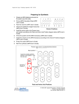
5 Ampere Charge of an 8 Henry Superconducting Magnet*
* 5 A charge of an 8.6 H AMI magnet with a 95 mA/s ramp rate;
output current monitor measured at 58.88 Hz. rate with a HP
34401 – data multiplied by 10× to obtain output current results.

Lake Shore Model 625 Superconducting MPS User’s Manual
Introduction 1-3
Parallel Operation
If an application requires more output current than a single Model 625 can provide, two supplies can be connected in
parallel for 120 A/5 V operation. Each unit is programmed for half of the total output current, operates independently,
and retains 0.1 mA resolution at 60 A operation. When the units are properly configured, either unit can detect a fault,
protect itself, and issue a fault output signaling the other unit to automatically enter the proper protection mode.
Persistent Switch Heater Output
The integrated persistent switch heater output is a controlled DC current source capable of driving most switch heaters. It
sources from 10 mA to 125 mA with a setting resolution of 1 mA and selectable compliance voltage of 12 V or 21 V.
The minimum load that the persistent switch heater can drive is 10 W. Persistent mode operation is integrated into the
instrument firmware to prevent mis-operation of the magnet.
Interfaces
The Model 625 includes IEEE-488 and RS-232C interfaces that provide access to operating data, stored parameters, and
remote control of all front panel operating functions. In addition, the Model 625 includes a trigger function that is used to
start an output current ramp. When the trigger is activated, either by an external trigger or by computer interface
command, the power supply will begin ramping to the new setpoint.
The Model 625 provides two analog outputs to monitor the output current and voltage. Each output is a buffered,
differential, analog voltage representation of the signal being monitored. The current monitor has a sensitivity of
1 V = 10 A, while the voltage monitor has a sensitivity of 1 V = 1 V.
Display and Keypad
The Model 625 incorporates a large 8-line by 40-character vacuum fluorescent display. Output current, calculated field
in tesla or gauss, output voltage, and remote voltage sense readings can be displayed simultaneously. Five LEDs on the
front panel provide quick verification of instrument status, including ramping, compliance, fault, PSH status, and
computer interface mode. Error conditions are indicated on the main display along with an audible beeper. Extended
error descriptions are available under the Status key.
The keypad is arranged logically to separate the different functions of the instrument. The most common functions of the
power supply are accessed using a single button press. The keypad can be locked to either lock out all changes or to lock
out just the instrument setup parameters allowing the output of the power supply to be changed.
Figure 1-1. Model 625 Front Panel

Lake Shore Model 625 Superconducting MPS User’s Manual
1-4 Introduction
1.2 SPECIFICATIONS
Output
Type: Bipolar, Four Quadrant, DC Current Source
Current Generation: Linear regulation with digital setting and analog control
Current Range: ±60 A
Compliance Voltage: ±5 V maximum (nominal, both source and sink)
Maximum Power: 300 W
Load Reactance: 0 H to 100 H
Current Ripple (Max): 4 mA RMS at 60 A, (0.007%) into 1 mΩ load
(significantly reduced into a reactive load or at lower current)
Current Ripple Frequency: Dominated by line frequency and its harmonics
Temperature Coefficient: ±15 ppm of full scale/°C
Line Regulation: 15 ppm/6% line change
Source Impedance: 25 Ω
Stability (1 h): 1 mA/h (after warm-up)
Stability (24 h): 10 mA/24 h (typical, dominated by temperature coefficient and line regulation)
Isolation: Output optically isolated from chassis to prevent ground loops
Parallel Operation: 2 units can be paralleled for ±120 A, ±5 V operation
Protection: Quench, Line Loss, Low Line Voltage, High Line Voltage, Output Over Voltage,
Output Over Current, Over Temperature, Remote Inhibit
(on critical error conditions, magnet discharges at 1 V nominal)
Output Programming
Internal Current Setting
Resolution: 0.1 mA (20 bit)
Settling Time: 600 ms for 1% step to within 0.1 mA into a resistive load
Accuracy: ±10 mA ±0.05% of setting
Operation: Keypad, computer interface
Protection: Current setting limit
Internal Current Ramp
Ramp Rate: 0.1 mA/s to 99.999 A/s (compliance limited)
Update Rate: 27.7 increments/s
Ramp Segments: 5
Operation: Keypad, computer interface, trigger input
Protection: Ramp rate limit
External Current Programming
Sensitivity: 6 V = 60 A
Resolution: Analog
Accuracy: ±10 mA ±1% of setting
Bandwidth (3 dB): 40 Hz, 2-pole, low-pass filter (10 Hz pass band, compliance limited)
Input Resistance: >50 kΩ
Operation: Voltage program through rear panel
Connector: Shared 15-pin D-sub
Limits: Internally clamped at 6.1V
Compliance Voltage Setting
Range: 0.1 V to 5.0 V
Resolution: 100 µV
Accuracy: ±10 mV ±1% of setting

Lake Shore Model 625 Superconducting MPS User’s Manual
Introduction 1-5
Readings
Output Current
Resolution: 0.1 mA
Accuracy: ±1 mA ±0.05% of reading
Update Rate: 2.5 readings/s display, 10 readings/s interface
Compensation: Compensated for lead resistance and 25 Ω source resistance
Output Voltage (at supply terminals)
Resolution: 100 µV
Accuracy: ±1 mV ±0.05% of reading
Update Rate: 2.5 readings/s display, 5 readings/s interface
Remote Voltage (at magnet leads)
Resolution: 100 µV
Accuracy: ±1 mV ±0.05% of reading
Update Rate: 1.25 readings/s
Input Resistance: >50 kΩ
Connector: Shared 15-pin D-sub
Persistent Switch Heater Output (PSHO)
Current Range: 10 mA to 125 mA
Compliance Voltage (minimum): 12 V or 21 V selectable
Heater Resistance (minimum): 10 Ω
Setting Resolution: 1 mA
Accuracy: ±1 mA
Operation: On/Off with lockout delay of 5 s to 100 s
Protection: Open or shorted heater detection, error message if off and on output currents differ
Connector: BNC
Front Panel
Display Type: 8-line by 40 character, graphic vacuum fluorescent display module
Display Readings: Output current, calculated field (T or G), output voltage, remote voltage sense
Display Settings: Output current, calculated field, compliance voltage, ramp rate
Display Annunciators: Status and errors
LED Annunciators: PSHO on, remote, compliance limit, fault, ramping
Keypad Type: 26 full travel keys
Keypad Functions: Direct access to common operations, menu driven setup
Interface
IEEE-488.2 Interface
Features: SH1,AH1,T5,L4,SR1,RL1,PP0,DC1,DT1,C0,E1
Reading Rate: To 10 readings/s
Software Support: National Instruments LabVIEW driver (consult Lake Shore for availability)
Serial Interface
Electrical Format: RS-232C
Baud Rates: 9600, 19200, 38400, 57600
Reading Rate: To 10 readings/s
Connector: 9-pin D-sub
Output Current Monitor
Sensitivity: 60 A = 6 V
Accuracy: ±1% of full scale
Noise: 1 mV
Source Impedance: 20 Ω
Connector: Shared 15-pin D-sub

Lake Shore Model 625 Superconducting MPS User’s Manual
1-6 Introduction
Output Voltage Monitor
Sensitivity: 1 V = 1 V
Accuracy: ±1% of full scale
Noise: 1 mV
Source Impedance: 20 Ω
Connector: Shared 15-pin D-sub
Fault Output
Type: Relay (closed on fault)
Relay Contact: 30 VDC @ 1 A
Connector: Shared 25-pin D-sub
Remote Inhibit Input
Type: TTL or contact closure
Connector: Shared 25-pin D-sub
Trigger Input
Type: TTL or contact closure
Connector: Shared 25-pin D-sub
General
Ambient Temperature: 15 °C to 35 °C
Cooling: Air cooled with internal 2 speed fan
Warm-up: 30 minutes at output current setting
Line Power: 100, 120, 220, 240 VAC +6% –10%, single phase, 50 or 60 Hz, 850 VA
Size: 483 mm W × 178 mm H × 520 mm D (19 in × 7 in × 20.5 in),
rack mount (integrated rack mount ears)
Weight: 27.2 kg (60 lbs)
Approval (pending): CE Mark – Low voltage compliance to EN61010-3, EMC compliance to EN55022-1
Calibration Schedule: 1 year
Ordering Information
Part Number Description
625 Superconducting Magnet Power Supply
625-DUAL Two Model 625s, one dual supply interconnect cable kit
Select a power configuration:
VAC-100-B Instrument configured for 100 VAC with U.S. power cord
VAC-120-B Instrument configured for 120 VAC with U.S. power cord
VAC-120-BC Instrument configured for 120 VAC with U.S. power cord and universal European
power cord and fuses for 220/240 setting (extra charge for this option)
VAC-220-C Instrument configured for 220 VAC with European power cord
VAC-240-C Instrument configured for 240 VAC with European power cord
VAC-220-D Instrument configured for 220 VAC with a 220 V (6-15P) U.S. power cord
Accessories included:
6271 Model 625 user's manual
6241 Two front handles
6242 Two rear handles/protectors
6243 Output shorting bar and terminal fasteners
6251 25-pin D-sub mating connector, digital I/O
6252 15-pin D-sub mating connector, analog I/O
— Calibration Certificate
Accessories available
117-017 1 m (3.3 ft) long IEEE-488 (GPIB) computer interface cable assembly
6261 10 ft – 60 A magnet cable kit, AWG 4
6262 20 ft – 60 A magnet cable kit, AWG 4
6263 Dual supply interconnect cable kit (including magnet cables and safety interlock cable)
CAL-625-CERT Instrument recalibration with certificate
CAL-625-DATA Instrument recalibration with certificate and data

Lake Shore Model 625 Superconducting MPS User’s Manual
Introduction 1-7
1.3 SAFETY SUMMARY
Observe these safety precautions during all phases of instrument operation, service, and repair. Failure to comply with
these precautions or with specific warnings elsewhere in this manual violates safety standards of design, manufacture,
and intended instrument use. Lake Shore assumes no liability for Customer failure to comply with these requirements.
The Model 625 protects the operator and surrounding area from electric shock or burn, mechanical hazards, excessive
temperature, and spread of fire from the instrument. Environmental conditions outside of the conditions below may pose
a hazard to the operator and surrounding area.
• Indoor use.
• Altitude to 2000 meters.
• Temperature for safe operation: 5 °C to 40 °C.
• Overvoltage category II.
• Pollution degree 2.
• Maximum relative humidity: 80% for temperature up to
31 °C decreasing linearly to 50% at 40 °C.
• Power supply voltage fluctuations not to exceed ±10%
of the nominal voltage.
Ground the Instrument
To minimize shock hazard, the instrument is equipped with a 3-conductor AC power cable. Plug the power cable into
an approved three-contact electrical outlet or use a three-contact adapter with the grounding wire (green) firmly
connected to an electrical ground (safety ground) at the power outlet. The power jack and mating plug of the power
cable meet Underwriters Laboratories (UL) and International Electrotechnical Commission (IEC) safety standards.
Ventilation
The instrument has ventilation holes in its side covers. Do not block these holes when the instrument is operating.
Do Not Operate in An Explosive Atmosphere
Do not operate the instrument in the presence of flammable gases or fumes. Operation of any electrical instrument in
such an environment constitutes a definite safety hazard.
Keep Away from Live Circuits
Operating personnel must not remove instrument covers. Refer component replacement and internal adjustments to
qualified maintenance personnel. Do not replace components with power cable connected. To avoid injuries, always
disconnect power and discharge circuits before touching them.
Do Not Substitute Parts or Modify Instrument
Do not install substitute parts or perform any unauthorized modification to the instrument. Return the instrument to an
authorized Lake Shore representative for service and repair to ensure that safety features are maintained.
Cleaning
Do not submerge instrument. Clean only with a damp cloth and mild detergent. Exterior only.
Moving and Handling
Four handles are provided for ease of moving and handling the Model 625. Always use at least two, and if possible
four, handles when carrying the unit.
1.4 SAFETY SYMBOLS

Lake Shore Model 625 Superconducting MPS User’s Manual
1-8 Introduction
This Page Intentionally Left Blank

Lake Shore Model 625 Superconducting MPS User’s Manual
Magnet System Design 2-1
CHAPTER 2
MAGNET SYSTEM DESIGN
2.0 GENERAL
This chapter provides information on general magnet system design. It is intended to give the user insight into
superconducting materials, superconducting magnets, persistent switches, Dewars, and cabling issues. For information
on how to install the Model 625 please refer to Chapter 3. Instrument operation information is contained in Chapter 4.
2.1 SUPERCONDUCTING MATERIALS
Superconducting materials have a very special property, that when cooled to very low temperatures, they become perfect
conductors of electricity. The transition to the superconducting state happens abruptly as the critical temperature is
reached. When the material is in its superconducting state, it has absolutely zero resistance. Such materials have a variety
of applications, one of which is for the construction of high field magnets.
The unique properties of superconductors make them ideal for use in high field magnets. Since a superconductor has no
resistance it requires no voltage to maintain a current through it. Magnet grade superconductors also have a very high
current density allowing a relatively small wire to carry a large amount of current that can be used to generate large
magnetic fields.
There are three properties that determine if a material is in its superconducting state. The first property is critical
temperature. A superconductor needs to be cooled in order to transition to a superconducting state. This temperature is
called its critical temperature. Most materials need to be cooled with liquid helium in order to reach their critical
temperatures although some ceramics have shown to have a critical temperature as high as 125 K which would be
suitable for nitrogen cooling.
The second property is critical current density. A superconducting wire can only carry a certain amount of current in its
superconducting state. The current density of a typical superconducting wire made from niobium-titanium is on the order
of 1010 A/m2, about three orders of magnitude greater than normal house wiring. If the critical current density is
exceeded, the wire will return to its normal resistive state.
The last property is critical field. A superconductor will return to its normal resistive state if it is exposed to a magnetic
field larger than its critical field. Superconducting wire such as niobium-titanium and niobium-tin have critical fields in
excess of 10 T and 20 T respectively. Elemental superconductors, such as lead, have very low critical fields, in this case
0.08 T, and are not suited for creating superconducting magnets.
All three of these properties are related to one another. For instance, a superconducting wire is able to carry more current
and withstand a higher magnetic field as it is cooled to a lower temperature. In the case of niobium-titanium, a common
superconducting wire, the critical temperature is 9.3 K but at that temperature both the critical field and critical current
density are both zero. At a temperature of 6 K, the critical field increases to approximately 7 T and at 4 K it is
approximately 11 T.
2.2 SUPERCONDUCTING MAGNETS
Superconducting magnets are wound from many turns of superconducting wire. They are used to generate magnetic
fields that are larger than can be achieved with permanent magnets or electromagnets or when field stability is important.
They can also be more economical to run than electromagnets since the power needed to maintain the charge is minimal.
2.2.1 Superconducting Magnet Construction
The magnetic field (B) that can be generated by a solenoid is given by the equation B=μ0In/l, where μ0 is the
permeability of air, I is the current in the wire, n is the number of turns, and l is the length of the solenoid. Most
superconducting magnets are wound using a conductor made from many fine strands of niobium-titanium (NbTi) or
niobium-tin (Nb3Sn) embedded in a copper matrix. The copper matrix is used for mechanical stability and to provide a
path for large currents in the case of a magnet quench. Typically, niobium-tin is only used in magnets that can generate
fields in excess of 9 Tesla because it is more expensive and harder to work with than niobium-titanium.

Lake Shore Model 625 Superconducting MPS User’s Manual
2-2 Magnet System Design
The superconducting wire is wound around a non-magnetic former made from aluminum, brass, stainless steel, or other
material as needed. The individual windings are electrically insulated by the insulation on the wire and by an epoxy that
is applied to the windings. The epoxy is also necessary to keep the individual windings from moving when the magnet is
charged.
Figure 2-1. Typical Superconducting Magnet
2.2.2 Magnet Inductance
The inductance of a solenoid (L) is defined as L = μ0n2A/l, where μ0 is the permeability of air, n is the number of turns, A
is the cross-sectional area of the coil, and l is the length of the solenoid. The inductance of superconducting magnets is
fairly large, typically between 10 and 100 Henries. The magnet’s inductance limits the rate at which the magnet can be
charged or discharged because of the increased voltage required to change current. The formula V = L (di/dt) relates
charging voltage to inductance where V is the charging voltage, L is the magnet inductance, and di/dt is the rate of
change in current. The Model 625 can charge a magnet up to a 5 V rate, although many magnets are not designed to be
charged at that rate. For instance, a 10 Henry magnet can be charged at a rate of 0.5 A/s with a 5 V limit. A rate of 0.1
A/s is more typical.
/