Page is loading ...

Page 1 of 10 ARF U-control Profile S141208
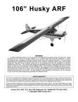
PROFILE P-47 & P-51
ARF U-CONTROL
GLOW-ENGINE OR EP-POWERED AIRPLANE
INSTRUCTION MANUAL
These ARF P-47 and
P-51 Profile models
are an easy-to-
transport, time-
proven design, ideal
for pilots who want a
versatile, great
flying sport airplane.
These profile models are offered with special thanks and appreciation to Mr. Charlie Bauer. As owner of
4π RC and a District VI AMA Vice President, Mr. Bauer designed and sold these airplanes as kits for many
years. Mr. Bauer recently gave his design to Richard Sang, owner of Maxford USA, so these airplanes could
be redesigned and reproduced for sale in today’s ARF market. We sincerely thank Mr. Bauer for his design,
for his review of our redesign, and for his valuable advice.
Changes in the ARF version include: a one-piece wing that separates from the fuselage for easy transport
and storage; a hatch on the underside of each wing panel; a lighter weight fuselage with open ‘channels’ for
an optional throttle and/or rudder servo’s extension; and a more scale-like profile appearance.
TABLE OF CONTENTS
I. Important safety precautions .............................. 1
II. Warranty, liability waiver, and return policy ..... 2
III. Specifications ..................................................... 3
IV. Special features of the PROFILE P-47 & P-51 ..... 3
V. Parts list ............................................................. 3
VI. Assembly instructions ................................ 4
VII. Setup and adjustments ............................... 9
VIII. Preparation for transport and field setup ... 9
IX. Preflight checks ......................................... 9
I. IMPORTANT SAFETY PRECAUTIONS TO PROTECT YOUR MODEL, YOURSELF & OTHERS:
1. This product should not be considered a toy, but rather a sophisticated, working model that functions much
like a full-scale airplane. Because of its performance capabilities, this product, if not assembled and operated
correctly, could cause injury to you or spectators and damage to property. Maxford USA provides you with a
high-quality, thoroughly tested almost-ready-to-fly model airplane with assembly instructions. However, the
quality and capabilities of your finished model airplane depend on how you assemble it, and your safety
depends on how you use and fly it. Any testing or flying of this model is done entirely at your own risk.
2. Assemble the model airplane according to these instructions. We recommend that you do not alter or modify
the model beyond the assembly options covered in these instructions, as doing so may result in an unsafe or
unworkable model. In a few cases the instructions may differ slightly from the photos; in those instances the
written instructions should be considered as correct. If you have any question or concern about these
instructions, before you proceed with assembly of this product, contact us at (562) 529-3988, Monday through
Friday, except national holidays, between 9 AM to 5 PM Pacific time.
Pictured with the included optional flaps installed.

Page 2 of 10 ARF U-control Profile S141208
3. It is your responsibility to install all control system and other components in such a way that this model
airplane passes all applicable safety tests and that the power system and controls operate smoothly and
correctly.
4. Recheck the operation of this model airplane before every flight to ensure that it is still operating correctly
and that the model has remained structurally sound. Also, before every flight check all leads, linkages,
clevises and other connections; do not fly without replacing any that you find damaged or defective.
5. If you are not an experienced U-control pilot or have not flown this type of model before, we strongly
recommend that you get the assistance of an experienced pilot.
6. Throughout the lifetime of this model, use only the Maxford USA-recommended or same-sized engine and a
new or well-maintained U-control system. If you are using electric power system or using a radio to control
any portion of the airplane, use only use the batteries and chargers recommended by the maker of your power
and/or radio systems.
7. While this kit has been flight-tested to meet or exceed our rigid performance and reliability standards in
normal use, if you plan to perform any extremely high-stress flying, such as racing or advanced aerobatics, or
if you plan to install a larger engine or motor than specified, you (the buyer or user of this product) are solely
responsible for taking any and all necessary steps to reinforce the high-stress points and/or substitute hardware
and/or linkages more suitable for such increased stresses.
II. WARRANTY, LIABILITY WAIVER, AND RETURN POLICY:
Maxford USA guarantees this kit to be free from defects in material and workmanship at the time of
purchase. All of our products have been inspected in our factory and are checked again when shipped from
our warehouse.
However, Maxford USA cannot directly control the materials you may use nor your final assembly process.
Therefore, Maxford USA can NOT in any way guarantee the performance of your finished model airplane.
Furthermore, in purchasing this product, you (the buyer or user of this product) exempt, waive, and relieve
Maxford USA from all current or future liability for any personal injury, property damage, or wrongful
death, and if you (the buyer or user of this product) are involved in any claim or suit, you will not sue
Maxford USA or any of its representatives.
If you do not fully accept the above liability and waiver, request a return merchandise authorization number
(RMA#) as explained in item 2 below.
If you think there is a missing part or any shipping damage, please read our after-sales service and return
policy as fully outlined below.
1. Inspect your order upon delivery for any shipping damage or missing part. If you find a problem,
you must contact us within 10 days from receipt of your purchase by calling (562) 529-3988,
Monday through Friday, except holidays, between the hours of 9 AM and 5 PM Pacific time.
During this telephone conversation, and with your support, we will determine how to resolve
your concern.
2. To request an RMA#, call (562) 529-3988, Monday through Friday, except holidays, between
the hours of 9 AM to 5 PM Pacific time. If we elect to issue you an RMA#, you must clearly
mark this RMA# on the outside of the package. (No return or exchange will be authorized after
10 days from the date of your receipt of the product; any package delivered to us without a
Maxford USA RMA# is subject to being returned to the sender, as received, with return postage
payable upon delivery.) Returned merchandise must be in its original condition as received from
Maxford USA, with no assembly or modification, in the original packing materials, complete
with all manuals and accessories. Return shipping and insurance charges must be prepaid by
you, the buyer.

Page 3 of 10 ARF U-control Profile S141208
3. Returned merchandise that is accepted by Maxford USA for credit is subject to a 10% to 20%
restocking fee (the final amount will be determined by Maxford USA upon receipt and
examination of the returned merchandise).
Return Address:
Maxford USA RC Model Distribution, Inc.
15939 Illinois Avenue #C
Paramount, CA 90723
IMPORTANT: Print the RMA# issued by Maxford USA on the package near the above address.
III. SPECIFICATIONS:
Wingspan ............................................................................................................................................ 52-inches
Wing Area ........... 637 sq. inches without flaps; 790 sq. inches when the included optional flaps are installed
Length ................................................................................................................................................. 40 inches
ARF weight ................................................................................................................... 2 pounds and 9 ounces
Engine (Not included) .................................................... 40-class (approx. .32 to .52 cubic inch) glow engine
or equivalent electric power system
Propeller (Not included) ........................ 10x6 (or as recommended for your engine or electric power system)
Control lines (Not included) ................................................... 52 feet (15.85 meters) or 60 feet (18.29 meters)
(All dimensions and weights are approximate.)
IV. SPECIAL FEATURES OF THE P-47 & P-51 PROFILE:
Preinstalled bellcrank and leadouts.
Hatch in the bottom of each wing panel for
access to control system components.
The hardwood engine-mounts may be drilled
to fit most popular engines.
The fuselage, wings and empennage are laser-
cut, jig-assembled balsa and light plywood.
All airframe assemblies are prefinished with
Mylar covering material.
Flaps are included and may be optionally
installed by customer.
Steerable tail wheel.
Customer’s choice to operate with a glow- or
electric-power system.
V. PARTS LIST:
1. Items you must supply to complete this
PROFILE P-47/-51 ARF U-Control airplane.
Epoxy glue, cyanoacrylate (CA) adhesive,
masking tape, a drill or high-speed rotary tool,
and a few common hand tools (such as long-
nosed and diagonal or side-cutter pliers, etc.).
.32- to .52-sized glow engine or equivalent
electric power system.
10x6 propeller or as recommended for your
power system.
*
*
Pictured with an optional electric power system

Page 4 of 10 ARF U-control Profile S141208
4 to 6 ounce fuel tank for a glow engine or a battery and controller for an electric power system.
Linkages for connection of the included optional flaps.
2. Items included with your ARF P-47 & P-51 PROFILE
Precovered fuselage, wing panels, vertical and
horizontal stabilizers, rudder, elevator and flaps.
Equipment bay in each wing panel with pre-
covered hatches, preinstalled bellcrank and wing-
tip leadouts.
Precut hinge slots, CA hinges, elevator pushrod.
Pre-bent steel rod main landing gear, 2-inch
diameter rubber wheels, steerable tail wheel strut
assembly with 1-inch diameter tail wheel and
mounting hardware.
This detailed, illustrated instruction manual,
control horns and leadout cables. (Items normally
supplied with engines or motors are not included).
VI. ASSEMBLY INSTRUCTIONS:
EMPENNAGE –
1. Test-fit the vertical and horizontal stabilizers in their mounting slots at the
rear of the fuselage.
2. Remove the Mylar covering that will be ‘buried’ inside the vertical and
horizontal stabilizers’ mounting slots. Use epoxy to secure the vertical and
horizontal stabilizers in their slots. Before the epoxy thickens, ensure the
vertical and horizontal stabilizers are aligned ‘square’ to the fuselage,
remove any excess epoxy, and allow the epoxy to cure fully.
3. Slide the tail wheel onto the tail-wheel strut and secure the wheel to its strut
with the smaller supplied wheel collar. Then slide the wire tail-wheel strut
into and fully through the hole in the end of the the tail-wheel’s mounting
bracket and assemble the steerable tail wheel as follows:
a) If necessary, cut off and discard the steering arm (only the cylinder-
shaped portion is needed to fit into the tail wheel’s mounting bracket).
b) Align the larger wheel collar’s threaded hole with the opening in the
side of the cylinder, press the wheel collar fully into the opening, and
start the bolt into the wheel collar.
c) With the exposed metal wheel collar facing away from the tail-wheel’s
mounting bracket, slide the cup-shaped cylinder fully onto the tail-
wheel’s strut. Tighten the wheel collar’s bolt onto the strut to secure the
strut to its mounting bracket.
4. Test-fit the elevator’s CA hinges into their precut slots in the elevator
and the horizontal stabilizer. Apply thin CA adhesive to secure the elevator
to the horizontal stabilizer.
5. At the top of the slot in the rudder’s leading edge, drill a 3/32-inch diameter
hole approx. 1/2- to 5/8-inch deep.
6. Temporarily position the rudder on the vertical stabilizer with tape. Hold the
tail-wheel’s mounting bracket at the bottom of the fuselage with the tail-
wheel’s wire strut aligned with the rudder’s hinge line.
7. Mark the strut where it needs to be bent to fit into the hole in the rudder.
Set to the same
distance on both
sides of the
f
usela
g
e
Rudder
Tail wheel’s
mounting
bracket
Tail wheel’s
wire strut

Page 5 of 10 ARF U-control Profile S141208
8. Remove the tape from the rudder and vertical stabilizer.
9. Bend the tail-wheel’s strut 90 degrees toward the rear (over the tail wheel) and cut off and discard all but 1/2-
inch of the bent end of the tail-wheel’s strut. Insert the bent end of the tail-wheel’s strut into the hole in the
rudder and secure the strut to the rudder with epoxy.
10. When the epoxy has cured fully, test-fit CA hinges into the precut slots in the rudder, vertical stabilizer and
the back edge of the fuselage. Use CA adhesive to secure each hinge.
11. Use wood screws to secure the tail-wheel assembly to the bottom of the fuselage. (Reinforce the holes in the
bottom of the fuselage with thin CA adhesive.)
12. Test-fit the rudder’s control horn on the left side of the rudder and the elevator’s control horn on the bottom-
right side of the elevator. Center the adjustment holes in each horn on its hinge line. Drill holes and attach the
rudder and elevator control horns with the supplied bolts and back plates.
13. Fit the rudder pushrod’s Z-bend into the rudder’s control horn and point the length of the pushrod toward the
nose.
14. Test-fit a control horn against the solid wood between the 2 openings on the left side of the fuselage at
approx. 2 1/2 inches forward of the rudder’s control horn. Mark where the control horn needs to be mounted
onto the side of the fuselage.
15. Mount an EZ-Link connector to a control horn and mount the control horn to the side of the fuselage.
16. Attach the rudder pushrod between the rudder’s control horn and the EZ-Link connector on the control horn
mounted on the side of the fuselage.
17. Set the angle of the rudder by adjusting the rudder’s pushrod in its EZ-Link connector. Tighten the EZ-Link
connector onto the rudder’s pushrod to secure the rudder.
WING –
1. Remove the wing’s center section
from the fuselage.
2. Test-fit the wing panels to the
wing’s center section by guiding
the two plywood wing spars into either wing panel, through the center section,
and fully into the second wing panel. (NOTE: The included bellcrank is pre-
installed at the root rib inside the RIGHT wing panel’s equipment bay; be sure to
position the equipment bay-hatch covers on the BOTTOM of the wing.)
3. Align each wing panel’s root rib with the center section.
4. Use epoxy to permanently secure the wing panels to the spar and center section.
5. If you will install the included optional flaps:
a) If necessary, cut through any Mylar covering the precut CA-hinge slots for
the flaps. Test-fit the flaps’ CA hinges into their slots in the flaps and the
wing panels.
b) Test-fit a wire flap coupler (not included) to the wing and mark where to cut
or drill an opening for the flap coupler in the wing’s center section and to
drill openings in the flaps for your flap coupler.
Twin plywood spars
Bellcrank

Page 6 of 10 ARF U-control Profile S141208
c) Cut or drill an opening through the wing’s center section for your flap coupler.
d) Fit the coupler through the wing’s center section and use epoxy to secure
the flap coupler into the flaps.
e) Use thin CA adhesive to secure the flaps to the wing.
FUSELAGE –
1. Test-fit both sides of the main landing gear struts into their slots on
the sides of the fuselage. Secure these main gear struts to the fuselage
with 8 ea. 10mm by 3mm wood screws and 4 ea. mounting straps,
then secure the wheels to the main gear with wheel collars.
2. If you are using a glow engine:
a) Test fit your engine centered in the mount and orient the
muffler below the cylinder. If necessary, sand or trim the
space between the engine mounting rails to fit your engine.
Mark and drill mounting holes for your engine. Apply epoxy
to fuel proof all exposed/raw wood.
b) Use mounting bolts, washers and self-locking nuts (not
supplied) to secure your engine to the fuselage.
c) Assemble your fuel tank’s vent and clunk lines in the
stopper and secure the stopper in your fuel tank’s opening.
d) Test fit your fuel tank on the side of the fuselage opposite
the cylinder head. We recommend you cut a 1/4- to 1/ 2-
inch thick piece of scrap foam rubber to insert between the
fuselage and the fuel tank to minimize foaming (not
included).
e) Choose whether to hold the fuel tank in position with nylon
cable ties, or to use J-bolts and rubber bands (not included).
Drill your mounting holes where the fuselage’s wood is
solid and install the fuel tank as shown in the photos on the
next page.
f) Install your engine’s muffler and attach the clunk and vent lines to the tank. Route the lines through the
nose and attach them to your engine’s carburetor and muffler’s pressure nipple.
3. If you are using an electric power system:
(NOTE: Your motor needs a minimum power rating of 400 Watts; we recommend using 3S or 4S Lipo
batteries and a motor controller rated at approx. 60 amps.)
a) To mount an electric motor to your P-47’s or P-51’s nose you need: 2 ea. 3/4-inch wide by approx.
2 3/4-inch long pieces of aluminum L-channel, 4 ea. #6 x 3/4-inch bolts,
4 ea. matching nuts, threadlock compound, hook-and-loop material and
the mounting hardware supplied with your motor.
b) Clamp the two pieces of L-channel together and drill four 3/16-inch
diameter holes through their ‘back-to-back’ mating surfaces in a
rectangular pattern measuring approx. 2 inches tall by 1/2-inches wide,
as shown at the right. Mark the pair of L-channels to identify their
matching ‘back-to-back’ holes.
c) Position the two pieces of L-channel with one on each side of the fuselage
at the front of the vertical surface in the space between the glow engine
beam mounts. Using the ‘back-to-back’ holes you drilled as a guide, drill
four 3/16-inch holes through the fuselage. Using the guide holes and 4 #6
2 3/4
inches
2
inches
1/2
inch
P
attern for
drilling both
aluminum
L
-channel’s
back-to-back
holes
Wire flap coupler
(not included)
Sample fuel tank mounting options

Page 7 of 10 ARF U-control Profile S141208
x 3/4-inch bolts and 4 ea. matching nuts, secure the two pieces of L-channel to the fuselage. Apply
thread-locking compound to secure the 4 ea. bolts and 2 ea. pieces of L-channel to the nose.
d) Test fit your motor and its mounting hardware to the two
forward-facing surfaces of the two pieces of L-channel.
Mark where holes are needed to mount your motor to the
L-channel. (NOTE: Depending on the outer diameter of
your motor, it may be necessary to increase the space
between the glow engine’s mounting rails. If so, we
recommend using a high speed motor tool with a sanding
drum, or you could use a course file and sandpaper.)
e) Drill the motor-mounting holes in the L-
channels’ forward-facing surfaces. Attach
your motor to the L-channel with hardware
provided by the maker of your motor. Use
threadlock compound to secure the motor to
the front faces of the two pieces of L-
channel.
f) For safety, we recommend you add a little
foam rubber at the front of each battery.
g) To optimize the balance of your P-47 or
P-51, we recommend mounting a battery on
each side of the fuselage in a series or
parallel configuration, depending on the
power requirements of your motor. As
shown at the right, make sure your batteries
are safely attached to the fuselage with
hook-and-loop material (not included).
4. Slide the wing’s center section into its mounting
grooves in the fuselage and secure the wing to
the fuselage with wood screws.
(NOTE: If being able to remove the wing
from the fuselage is not a feature you value,
you may permanently attach the wing to the
fuselage with epoxy.)
5. When setting up an electric power system and
using a radio receiver for throttle control, wrap
the receiver in foam rubber (not included) and
position the receiver inside the equipment bay
in the right side of the wing. Use small wood
screws to attach the hatch covers.
6. Guide the free end of each leadout wire through
a crimp tube, through the hole in the end of the bellcrank, then
back through the crimp tube. Adjust the leadout wires to the
same length and ajust the size of the resultant loop as shown at
the right.

Page 8 of 10 ARF U-control Profile S141208
7. Use pliers to crimp each tube onto its cable. Snip off the excess elevator
cable‟s ends with a pair of cutting pliers and discard the excess cable.
(NOTE: For your safety, do NOT leave any strands of wire poking out from
the end of the crimp tubes. Exposed small steel strands can be sharp enough
to cut or abrade skin!)
8. Install the elevator pushrod.
a) Guide the straight end of the supplied
1.5 mm pushrod through the slot in the
bottom of the right-side wing’s trailing
edge.
b) As shown at the right, guide this
pushrod into the EZ-Link connector on
the bellcrank.
c) Snug the EZ-Link connector’s
clamping bolt onto the end of the
1.5 mm pushrod.
d) Guide the pushrod’s Z-bend
into the outer hole in the
elevator’s control horn.
e) Slide a length of heat-shrink
tubing onto the free end of
the pushrod.
f) Insert the end of the wire
pushrod with the “L-bend”
into the hole in the wooden
pushrod.
g) Secure the metal pushrod into
its hole with CA adhesive.
h) Slide the tubing over the wire pushrod and shrink the tubing to secure the pushrod assembly as shown
above.
i) Adjust the length of the pushrod by centering the bellcrank and positioning the 1.5 mm pushrod in its
EZ-Link connector to set the elevator to “neutral” (neither UP nor DOWN).
Congratulations! Assembly is finished!
VII. SETUP AND ADJUSTMENTS:
1. We recommend the center of gravity (CG) should fall approx. 4 inches back from the leading edge of
the wing for your initial flight. If necessary, move the battery and/or add weight to the nose or tail to
ensure the CG is correct. Once you have determined the final position of your battery, secure the battery
in the equipment bay with double-sided foam tape, then pack the area around the battery and the
receiver with soft foam rubber to help secure and protect them against vibration.
2. Check the Mylar covering material’s joints and surfaces. If necessary, carefully use an iron on medium
heat to secure the edges and to tighten any loosened areas. Recheck and retighten from time to time.
3. Review your motor controller and/or radio’s instruction manual if you require assistance with any radio-
related setup or adjustment questions.

Page 9 of 10 ARF U-control Profile S141208
4. Control throws:
a) Initial settings:
Elevator ........................................................... +15 degrees (+1-inch)
Rudder .................................. 2 to 5 degrees (approx. 1/4-inch) offset toward the right
b) We recommend you wait to readjust the elevator throw, rudder offset and CG to your preference until
after you have become comfortable with the performance of your ARF U-control profile P-47 or P-51.
VIII. PREPARATION FOR TRANSPORT AND FIELD SETUP:
We recommend your U-control profile P-47 or P-51 be transported and stored fully assembled due to its sturdy
and securely attached wing. Nonetheless, if space is a problem, you may very carefully…
1. Unscrew and safely store the screws that attach the wing
to the fuselage. We suggest NOT disconnecting the
elevator pushrod; simply store the wing alongside the
fuselage.
2. Reattach the wing by reversing the above procedure.
IX. PRE-FLIGHT CHECKS:
1. Double-check the security of the engine (or motor), and
make certain that all screws, linkages, clevises and other
connections throughout the air frame are secure.
2. Double-check the control directions and amount of throw of the elevator before each flight.
3. If you use a radio to control the throttle and/or rudder, as with all radio-controlled model airplanes, this
model must pass the radio-range ground check recommended by your radio system’s manufacturer, or you
may not safely fly.
REMINDER: An important notice to our customers! This model airplane is NOT a toy.
Any testing or flying of this model airplane is done entirely at your own risk.
The quality and capabilities of your finished model airplane depend on how you assemble it.
Your safety depends on how you use and fly it.
Any testing or flying of this model airplane is done entirely at your own risk.
Stay clear of the propeller and the propeller’s arc.

Page 10 of 10 ARF U-control Profile S141208
PLEASE ENJOY YOUR HOBBY AND FLY SAFELY!
Designed by: Maxford USA RC Model Mfg., Inc.
Distributed by: Maxford USA RC Model Distribution, Inc.
15939 Illinois Avenue #C Telephone (voice) ............ (562) 529-3988
Paramount, CA 90723 Fax ................................... (562) 529-6988
Toll free (orders only) .... (866) 706-8288
Website .............. www.maxfordusa.com
REMEMBER: THE MODEL AIRPLANES YOU ARE FLYING ARE NOT TOYS.
ANY TESTING OR FLYING OF YOUR MODEL AIRPLANE
IS DONE ENTIRELY AT YOUR OWN RISK.
/