Page is loading ...

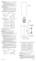
MOUNTING STRAP
ABRAZADERA DE MONTAJE
1) Pass wire from fixture through stem and screw stem to
coupling on top of fixture body.
NOTE: Thread locking compound must be applied to all
stem threads as noted with symbol () to prevent accidental
rotation of fixture during cleaning, relamping, etc.
2) Pass fixture wire through remaining stems and screw stems
together.
3) Pass fixture wire through the swivel and canopy assembly.
Thread end of swivel into last stem.
NOTE DIRECTION OF SWIVEL IN ACCORDANCE WITH
CEILING.
4) TURN OFF POWER.
IMPORTANT: Before you start, NEVER attempt any work
without shutting off the electricity until the work is done.
a) Go to the main fuse, or circuit breaker, box in your
home. Place the main power switch in the “OFF” position.
b) Unscrew the fuse(s), or switch “OFF” the circuit breaker
switch(s), that control the power to the fixture or room
that you are working on.
c) Place the wall switch in the “OFF” position. If the fixture
to be replaced has a switch or pull chain, place those in
the “OFF” position.
5) Find the appropriate threaded holes on mounting strap.
Assemble driver bracket using the screws provided to the
mounting strap.
6) Attach mounting strap to outlet box. (Screws not provided).
Mounting strap can be adjusted to suit position of fixture.
7) Grounding instructions: (See Illus. A or B).
A) On fixtures where mounting strap is provided with a hole
and two raised dimples. Wrap ground wire from outlet
box around green ground screw, and thread into hole.
B) On fixtures where a cupped washer is provided. Attach
ground wire from outlet box under cupped washer and
green ground screw, and thread into mounting strap.
If fixture is provided with ground wire. Connect fixture
ground wire to outlet box ground wire with wire connector.
(Not provided.) After following the above steps. Never
connect ground wire to black or white power supply wires.
8) Make primary wire connections (connectors not provided)
joining the white driver wire to the white supply wire, and the
black driver wire to the black supply wire. DO NOT CONNECT
THE RED AND BLUE SECONDARY WIRES TO THE SUPPLY
WIRES.
9) Make the secondary wire connections (red and blue driver
wires to fixture wire) using the provided wire nuts, trimming
fixture wires if necessary. Reference chart below for correct
connections and wire accordingly.
10) Separate the primary and secondary connections, ensuring
that they remain on opposite sides of the driver while
bringing the fixture to the ceiling.
11) Align the side canopy holes with the driver bracket, and
secure the fixture to the ceiling be installing both of the
mounting screws.
Connect Secondary
BLUE Driver Wire to:
Connect Secondary
RED Driver Wire to:
Blue or Black Red or White
*Parallel cord (round & smooth)
*Parallel cord (square & ridged)
Clear, Brown, Gold or Black
without Tracer
Clear, Brown, Gold or Black
with Tracer
Insulated wire (other than green)
with copper conductor
Insulated wire (other than green)
with silver conductor
*Note: When parallel wire (SPT I & SPT II)
are used. The neutral wire is square shaped
or ridged and the other wire will be round in
shape or smooth (see illus.)
Neutral Wire
Date Issued: 3/21/14
IS-42517-US
CANOPY
ESCUDETE
STEM
VÁSTAGO
SWIVEL
UNIÓN GIRATORIA
4
FIXTURE BODY
CUERPO DEL ARTEFACTO
SEE OTHER SIDE FOR SPANISH TRANSLATIONS.
VEA EL OTRO LADO DE TRADUCCIONES AL ESPAÑOL.
GREEN GROUND
SCREW
CUPPED
WASHER
A
B
OUTLET BOX
GROUND
FIXTURE
GROUND
DIMPLES
WIRE CONNECTOR
(NOT PROVIDED)
OUTLET BOX
GROUND
GREEN GROUND
SCREW
FIXTURE
GROUND
We’re here to help 866-558-5706
Hrs: M-F 9am to 5pm EST
SCREW
TORNILLO
DRIVER BRACKET
SOPORTE DEL
CONTROLADOR
DRIVER
CONTROLADOR

3
1) Pass wire from fixture through stem and screw stem to
coupling on top of fixture body.
NOTE: Thread locking compound must be applied to all
stem threads as noted with symbol (3) to prevent accidental
rotation of fixture during cleaning, relamping, etc.
2) Pass fixture wire through remaining stems and screw stems
together.
3) Pass fixture wire through the canopy and swivel assembly.
Thread small threaded pipe into end of swivel.
NOTE DIRECTION OF SWIVEL IN ACCORDANCE WITH
CEILING.
4) TURN OFF POWER.
IMPORTANT: Before you start, NEVER attempt any work
without shutting off the electricity until the work is done.
a) Go to the main fuse, or circuit breaker, box in your
home. Place the main power switch in the “OFF”
position.
b) Unscrew the fuse(s), or switch “OFF” the circuit breaker
switch(s), that control the power to the fixture or room
that you are working on.
c) Place the wall switch in the “OFF” position. If the fixture
to be replaced has a switch or pull chain, place those in
the “OFF” position.
5) Find the appropriate threaded holes on mounting strap.
Assemble mounting screws into threaded holes.
6) Attach mounting strap to outlet box. (Screws not provided).
Mounting strap can be adjusted to suit position of fixture.
7) Make primary wire connections (connectors not provided)
joining the white driver wire to the white supply wire, and the
black driver wire to the black supply wire. DO NOT CONNECT
THE RED AND BLUE SECONDARY WIRES TO THE SUPPLY
WIRES.
8) Make the secondary wire connections (red and blue driver
wires to fixture wire) using the provided wire nuts, trimming
fixture wires if necessary. Reference chart below for correct
connections and wire accordingly.
9) Separate the primary and secondary connections, ensuring
that they remain on opposite sides of the driver while
bringing the fixture to the ceiling.
10) Align the side canopy holes with the driver bracket, and
secure the fixture to the ceiling be installing both of the
mounting screws.
Connect Secondary
BLUE Driver Wire to:
Connect Secondary
RED Driver Wire to:
Blue or Black Red or White
*Parallel cord (round & smooth)
*Parallel cord (square & ridged)
Clear, Brown, Gold or Black
without Tracer
Clear, Brown, Gold or Black
with Tracer
Insulated wire (other than green)
with copper conductor
Insulated wire (other than green)
with silver conductor
*Note: When parallel wire (SPT I & SPT II)
are used. The neutral wire is square shaped
or ridged and the other wire will be round in
shape or smooth (see illus.)
Neutral Wire
Date Issued: 3/21/14 IS-42517-CB
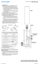
INSTRUCTIONS
For Assembling and Installing Fixtures in Canada
Pour L’assemblage et L’installation Au Canada
MOUNTING STRAP
PATTE DE FIXATION
CANOPY
CACHE
STEM
TIGE
SWIVEL
PIVOT
3
SEE OTHER SIDE FOR CANADIAN FRENCH TRANS-
LATIONS.
VOIR L’AUTRE CÔTÉ POUR LES CANADIENS TRA-
DUCTIONS EN FRANÇAIS.
3
3
3
We’re here to help 866-558-5706
Hrs: M-F 9am to 5pm EST
SCREW
VIS
DRIVER BRACKET
SUPPORT DE
L’ÉTRIER
DRIVER
L’ÉTRIER
/