ACV HeatMaster 200 N / 200 F (v13) : Operating instructions

Type
Operating instructions
ENFRRU PL DE IT ES NL
EN • 1
HeatMaster 200 N / 200 F : 664Y6300 • B
INSTALLATION, OPER ATION AND
MAINTENANCE INSTRUCTIONS
HeatMaster
®
200 N
200 F
Addendum Gas Appliances : A1005007 - ADD0000
Addendum - Additional Safety Instructions for Gas Appliances
APPLICABILITY : 664Y4900 - Rev E - Delta Pro S -Pro Pack, Installation, Operation and Maintenance Instructions
664Y6100 - Rev B - HeatMaster 71 - 101 - 201 (V13), Installation, Operation and Maintenance Instructions
664Y6300 - Rev B - HeatMaster 200N, Installation, Operation and Maintenance Instructions
664Y6700 - Rev D - Prestige 24-32 Solo/Excellence, Installation, Operation and Maintenance Instructions
664Y6900 - Rev D - HeatMaster 25 - 35 - 45 - 70 - 85 - 120 TC, Installation, Operation and Maintenance Instructions
664Y7000 - Rev B - HeatMaster 25C, Installation, Operation and Maintenance Instructions
664Y7200 - Rev B - Compact Condens 170 - 210 - 250 - 300, Installation, Operation and Maintenance Instructions
664Y7300 - Rev C - WaterMaster 25 - 35 - 45 - 70 - 85 - 120, Installation, Operation and Maintenance Instructions
EN
EN
FR
FR
NL
NL
DE
DE
ES
ES
IT
IT
PL
PL
RU
RU
Make sure that the appliance is connected to the earth.
Check that the gas type and pressure from the distribution network are compatible with the
appliance settings.
Vérier que le type de gaz et la pression du réseau de distribution sont compatibles avec les
réglages de l’appareil.
Controleer of het type gas en de druk van het distributienetwerk in overeenstemming zijn
met de toestelinstellingen.
Compruebe que el tipo de gas y la presión de la red de distribución son compatibles con los
ajustes del aparato.
Controllare che il tipo di gas e la pressione della rete di distribuzione siano compatibili con
le impostazioni dell’apparecchio.
Stellen Sie sicher, dass die Gasart und der Druck des Verteilungsnetzes mit den Geräteinstel-
lungen kompatibel sind.
Sprawdzić, czy typ gazu i ciśnienie sieci dystrybucyjnej są zgodne z ustawieniami urządzenia.
Убедитесь, что тип газа и давление в распределительной сети совместимы с настройка-
ми прибора.
Veiller à ce que l’appareil soit raccordé à la terre.
Zorg ervoor dat het toestel is geaard.
Asegúrese de que el aparato esté conectado a tierra.
Assicurarsi che l’apparecchio sia elettricamente collegato alla messa a terra dell’impianto.
Stellen Sie sicher, dass das Gerät geerdet ist.
Upewnij się, że urządzenie jest uziemione.
Убедитесь, что прибор заземлен.
ENFRRU PL DE IT ES NL
EN • 2
HeatMaster 200 N / 200 F : 664Y6300 • B
TABLE OF CONTENTS
WARNINGS 3
Who should read these Instructions 3
Symbols 3
Warnings 3
Recommendations 3
USER’S GUIDE 4
Use of the boiler 4
Burner safety mechanism 5
Burner Troubleshooting 5
APPLIANCE DESCRIPTION 6
TECHNICAL CHARACTERISTICS 7
Dimensions 7
Burner chamber plate 7
Boiler clearance 7
Combustion characteristics 8
Hydraulic characteristics 8
Domestic hot water performance 8
Maximum operating conditions 8
Chimney connection characteristics 9
Boiler room 9
Chimney connection 9
Electrical characteristics 10
INSTALLATION 11
Package contents 11
DHW connection 12
Heating connection 13
STARTING UP 14
Filling the DHW and heating circuits 14
Starting the boiler 14
Bleeding the heating circuit 14
MAINTENANCE 15
Annual maintenance 15
Boiler maintenance 15
Maintenance of the safety devices 15
Burner maintenance 15
Draining the boiler 15
DECLARATION OF CONFORMITY - EC 16
SPARE PARTS
www.acv.com
CERTIFICATION
The appliances bear the “CE” mark, in accordance with the standards in force in the various countries [European Directives 92/42/EEC
“Efficiency”, 2009/142/EC “Gas Appliances”. These appliances also bear the Belgian gas boiler quality labels “HR+”[gas boiler] and
“Optimaz” (oil boilers) labels.
Certified quality system ISO 9001
ENFRRU PL DE IT ES NL
EN • 3
HeatMaster 200 N / 200 F : 664Y6300 • B
WHO SHOULD READ THESE INSTRUCTIONS
The manual should be read by:
- The specifying engineer
- The user
- The installer
- The maintenance technician
SYMBOLS
The following symbols are used in this manual:
RECOMMENDATIONS
Please carefully read this manual before installing and starting
up the boiler.
It is prohibited to carry out any modifications to the inside of
the appliance without the manufacturers prior and written
agreement.
The product must be installed and serviced by an approved and
qualified engineer, in accordance with applicable standards and
regulations.
Failure to comply with the operation instructions and test
procedures can result in personal injury or a risk of environmental
pollution.
To guarantee safe and correct operation of the appliance, it is
important to have it serviced and maintained every year by an
approved installer or maintenance contractor.
In case of anomaly, please call your service engineer.
• In spite of the strict quality standards that ACV applies to its
appliances during production, inspection and transport, faults
may occur. Please immediately notify your approved installer of
any faults.
The defective parts may only be replaced by genuine factory
parts.
• Before carrying out any work on the boiler, it is important to
isolate the electrical supply to the unit.
• The user must not attempt to gain access to the components
inside the boiler or the control panel.
This appliance is not intended for use by persons (including
children) with reduced physical, sensory or mental capabilities,
or lack of experience and knowledge, unless supervised or
unless they have been given instruction concerning the use of
the appliance by a person responsible for their safety.
WARNINGS
WARNINGS
If you smell gas:
- Immediately isolate the gas supply.
- Open windows and doors to ventilate the area.
- Do not use any electrical appliances and do not operate any switches.
- Immediately notify your gas supplier and/or your installer.
This manual is part of the items delivered with the appliance and must
be given to the user and stored in a safe place!
An approved installer must carry out the installation, starting up,
maintenance and repair of the system, in accordance with current
standards in force.
The manufacturer declines all liability for any damage caused as a
result of incorrect installation or in the event of the use of appliances or
accessories that are not specified by the manufacturer.
The manufacturer reserves the right to change the
technical characteristics and features of its products
without prior notice.
The availability of certain models as well as their
accessories may vary according to markets.
Risk of scalding
Essential instruction for the safety of persons and
the environment
Danger of electrocution
Essential instruction for the correct operation of
the installation
ENFRRU PL DE IT ES NL
EN • 4
HeatMaster 200 N / 200 F : 664Y6300 • B
USER’S GUIDE
USING THE BOILER
Make sure to have your installation inspected and main-
tained, if required, at least once a year by an approved
and qualified engineer. More frequent servicing may be
required depending on boiler use. If this is the case, con-
sult your installer for advice.
Starting the burner:
In normal operation, the burner starts automatically as
soon as the boiler temperature drops below the set tem-
perature.
GETTING FAMILIAR WITH THE CONTROL PANEL
The user must not attempt to gain access to the components inside the
control panel.
• Master switch
Is used to turn the HeatMaster® on or off.
• Control thermostat - 60-90 °C
When using the HeatMaster® as a hot water generator only, the
temperature can be set between 60 °C and 90 °C. If the HeatMaster®
is used for both domestic hot water (DHW) and central heating, the
control thermostat would normally be set at 80 °C to achieve optimum
operating conditions.
• Summer/winter switch
Is used to turn the heating pump (if fitted) on or off.
• Manual reset high limit thermostat
If the boiler temperature exceeds 103 °C, this safety device will activate
and the high temperature indicator will light up. To reset - first allow the
boiler to cool to below 60 °C, unscrew the cap and press the reset button
using a pencil or similar pointed device, then reinstall the cap. If the fault
persists, turn the boiler off and call a service engineer.
• Daily timer
Allows the HeatMaster® to be turned on and off at specific moments of
the day and operates on a 24 hour sequence. A series of white tabs are
set around the timer, each tab corresponding to a 15 minute switching
period. To set the timer, simply push outwards the number of tabs
required for ON period.
Remember: Tab in = HeatMaster® OFF
Tab out = HeatMaster® ON
• Temperature and pressure gauge
This gauge indicates both the temperature of the HeatMaster® and the
pressure within the primary circuit. The temperature should not exceed
90 °C - if it does, switch the boiler off and check the thermostat setting.
If the fault persists, call an engineer. The pressure should not fall below
1 bar, if it does, please see the ‘Heating System Pressure’ paragraph
further in this section.
• Low primary water pressure indicator
If this indicator lights up, the primary circuit of the HeatMaster®
requires topping up with water. Please see the ‘Heating System
Pressure’ paragraph later in this section.
1. Burner safety cutout warning indicator
2. Low primary water pressure indicator
3. High limit thermostat indicator
4. Temperature and pressure gauge
5. Control thermostat
6. Daily timer
7. Manual reset high limit thermostat
8. Master switch
9. Summer/winter switch
HeatMaster® 200 N and 200 F Control Panel
I
O
1
4
53
2
76
8 9
ENFRRU PL DE IT ES NL
EN • 5
HeatMaster 200 N / 200 F : 664Y6300 • B
Heating System Pressure
From time to time you may need to top up the heating circuit
water level to get the required pressure in the system. The
circuit pressure is indicated by the combined temperature
and pressure gauge on the boiler control panel.
The minimum pressure when the boiler is cold should be 1
bar. The precise operating pressure required depends on the
height of the building and your installer will have informed
you of this value at the time of installation (see Starting up
section - Filling the DHW and heating circuits).
If the pressure falls below 1 bar, the boiler water pressure
switch will turn the boiler off until the pressure is restored
To restore the pressure, top up the heating circuit with water
by opening the filling valve
of the boiler primary circuit
and allow the system to fill. Once the pressure gauge of the
boiler control panel indicates the required pressure, close the
filling valve.
Safety valves
If water discharges from any of the safety valves, turn the boiler off and
call a service engineer.
BURNER SAFETY MECHANISM
RESETTING THE OIL BURNER
HeatMaster® 200 F
The safety lockout indicator is located on the burner and on the
control panel.
The red warning light indicates an operating fault.
Wait 5 minutes before resetting the burner. To reset: press the button
located on the burner.
If the burner does not restart, call a service engineer after ensuring the
fault is not due to a power failure or low oil level in the tank.
BURNER TROUBLESHOOTING
For all burners, please refer to the relevant servicing and troubleshooting
instructions in the technical manual of your burner.
USER’S GUIDE
A
I
O
ENFRRU PL DE IT ES NL
EN • 6
HeatMaster 200 N / 200 F : 664Y6300 • B
APPLIANCE DESCRIPTION
Description HeatMaster® 200 N / 200 F
1. Chimney reduction with horizontal outlet
(verticaloutlet optional)
2. Cold water inlet
3. T&P valve connection (optional)
4. Auto-air vent
5. Rigid polyurethane foam insulation
6. Flue gas tubes and turbulators
7. Burner chamber plate
8. Charging pump (2x)
9. Heating flow
10. Domestic hot water outlet
11. Primary expansion vessel (4x)
12. Internal stainless steel tank
13. Heating return
14. Drain cock
15. Primary circuit tank
16. Combustion chamber
A. Automatic reset high limit thermostat
B. Manual reset high limit thermostat
C. Thermometer
D. DHW priority thermostat
E. Low water pressure switch
F. Pressure gauge connection
G. Thermostat control bulb
H. Primary circuit safety valve
10
9
11
12
14
15
16
1
2
3
4
5
7
8
13
6
BA
E
H
D
F
G
C
ENFRRU PL DE IT ES NL
EN • 7
HeatMaster 200 N / 200 F : 664Y6300 • B
TECHNICAL CHARACTERISTICS
DIMENSIONS
F
C
A
B
D
C
A
B
E
2385
2115
590
325
2225
1975
1020 1020
600
510
510
HeatMaster® 200 N
Weight empty
HeatMaster® 200 F
Weight empty
45°
Ø 130
Ø 170
Ø 22
Ø 46
4 x M8
BURNER CHAMBER PLATE
The burner chamber plate has four threaded holes (M8) to attach the
burner It is protected from heat by a blanket insulation.
BOILER CLEARANCE
Recommended Minimum
A (mm) 650 500
B (mm) 800 700
C (mm) 500 300
D (mm) 300 250
E (mm) 150 100
F (mm) 800 700
ENFRRU PL DE IT ES NL
EN • 8
HeatMaster 200 N / 200 F : 664Y6300 • B
TECHNICAL CHARACTERISTICS
COMBUSTION CHARACTERISTICS
HEATMASTER®
HeatMaster® 200 N HeatMaster® 200 F
Fuel Type Oil/Gas Oil
Input max. (PCI) kW 154 196
Output max. (80/60°C) kW 142 180
Maintenance loss at 60°C as % of rated value % 0,43 0,34
Efficiency (max output) 80/60°C % 92,0 92,0
Combustion efficiency at 100% % 93,1
Class NOx 5
CARACTÉRISTIQUES HYDRAULIQUES
HeatMaster® 200 N HeatMaster® 200 F
Heating Connection [F] Ø 2” 2”
DHW Connection [M] Ø 2” 2”
Primary circuit water pressure drop (∆T = 20K) mbar 118 190
Total capacity L 641 641
Primary circuit capacity L 241 241
HYDRAULIC CHARACTERISTICS *
OPERATING CONDITIONS AT 9C
HeatMaster® 200 N HeatMaster® 200 F
Peak flow at 4C [T = 30 K] L/10 1570 1675
Peak flow at 45°C [∆T = 35 K] L/10 1350 1444
Peak flow at 4C [T = 30 K] L/60 4920 5976
Peak flow at 45°C [∆T = 35 K] L/60’ 4221 5131
Constant flow at 4C [T = 30 K] L/h 4020 5161
Constant flow at 45°C [∆T = 30 K] L/h 3446 4424
Heating time from 10 to 80°C minutes 29 27
*** For DHW temperatures > 45°C (∆T > 35K), please contact ACV
The temperature of the domestic hot water can be adjusted up to 90 °C in the boiler. However, the temperature of the domestic hot
water at the drawing point must comply with local regulations. For special applications, please contact ACV.
BURNER
All the HeatMaster® 200 N boilers can be equipped with an oil or gas burner available on the market.
The HeatMaster® 200 F is factory delivered with a Riello RG4S oil burner.
MAXIMUM OPERATING CONDITIONS
Maximum Service Pressure (DHW tank full of water)
- Primary circuit 3 bar
- DHW circuit 8,6 bar
Maximum Operating Conditions
- Maximum temperature of primary fluid 90 °C
- Minimum temperature of primary fluid 60 °C
Water Quality
• Chlorides ≤ 150 mg/l (304)
• 6 ≤ pH ≤ 8
ENFRRU PL DE IT ES NL
EN • 9
HeatMaster 200 N / 200 F : 664Y6300 • B
TECHNICAL CHARACTERISTICS
BOILER ROOM
- make sure that all air vents are unobstructed at all times.
- do not store any flammable products in the boiler room.
- do not store any corrosive products, paint, solvents, salts, chloride
products and other detergent products near the appliance.
- if you smell gas, do not switch on or off any lights, turn off the gas
meter, ventilate the rooms and contact your installer.
- The base on which the boiler rests must be made of non-combustible
materials.
CHIMNEY CONNECTION
- Chimney connection must comply with the applicable standards (NBN
D51-003 in Belgium), and take into account the local requirements
of the energy provider, the fire requirements and the regulation on
"noise pollution".
- The flue pipe size must not be smaller than the size of the boiler outlet
connection
B23 type chimney connection
The boiler is connected to the chimney by a metal pipe rising at an angle
from the boiler to the chimney. A flue disconnection piece is required.
It must be easily removable to give access to the flue pipes when
performing boiler maintenance.
Minimum supply of fresh air into
the boiler room
Fresh air supply
Haute = A Basse = B
HeatMaster® 200 N cm
2
≥ 250 ≥ 500
HeatMaster® 200 F cm
2
≥ 250 ≥ 600
Dimensions of a B23
type chimney
Height = L
5 m 10 m 15 m
HeatMaster® 200 N Ø mm 300 250 250
HeatMaster® 200 F Ø mm 320 270 250
Note:
Given that regulations vary from one country to another,
the table above is given by way of indication only.
Due to the high efficiency of our boilers, the flue gases
are released at low temperature. As a result, there is a risk
of condensation of the flue gases, which could damage
some chimney constructions; to avoid this risk, it is
strongly recommended to line the chimney. To prevent
condensates to flow back into the boiler, we strongly
advise to install a condensates collector.
Please contact your installer for more information.
CHIMNEY CONNECTION CHARACTERISTICS
HeatMaster® 200 N HeatMaster® 200 F
Volume of the combustion chamber m
3
0,14 0,14
Mass flow rate of combustion products g/s 83,0
Max. pressure drop in flue pipe Pa 130 170
Flue pipe diameter mm 250 250
Net temperature °C 143 147,5
B23
B
23
A
B
L
ENFRRU PL DE IT ES NL
EN • 10
HeatMaster 200 N / 200 F : 664Y6300 • B
M
M
L1 N PE
P
t
t
t
23
22
21
20
18
17
16
15
13
12
108
9
7
6
5
4
3 211
1
P
12
t
P
12
C
21
3 1
54
2
t
C
21
t
C
21
32
1
5
12
11
13
M
13
14
10
16
17
15
8
7
6
4
Br
B
Br
Br
O
G
Pk
B
B
B
B
B
Y/Gr
B
B
Y/Gr
B
Y/Gr
Y/Gr
Y/Gr
B
B
G
Gr
Pk
B
B R
B
B
Pk
R
Br
Y
BkBk
W
Br
O
O
W
W
O
O O
O W W
Bk
22
Pk
B
W
BkGBr
W W
G
B
B
O
Br
Br
G
Bk
Pk
B
B
B
Y/Gr
Y/Gr
L T1
T2 S3
N PE
G
9
B Br
Y/Gr
TECHNICAL CHARACTERISTICS
ELECTRICAL CHARACTERISTICS
WIRING DIAGRAM
1. 230 Volt electrical supply connection plug
2. Master switch
3. High limit thermostat indicator
4. Manual reset high limit thermostat
5. Low primary water pressure indicator
6. Low water pressure switch
7. Daily timer
8. Summer/winter switch
9. DHW priority thermostat
10. Burner safety cutout warning indicator
11. Room temperature (option))
12. Heating pump (option)
13. Charging pump HeatMaster®
14. Burner
15. Flow rate sensor (option)
16. Automatic reset high limit thermostat (95°C)
17. Control thermostat
B. Blue
Bk. Black
Br. Brown
G. Grey
Gr. Green
O. Orange
Pk. Pink
R. Red
W. With
Y. Yellow
Y/Gr. Yellow / Green
MAIN ELECTRICAL CHARACTERISTICS
HeatMaster® 200 N 200 F
Operating voltage V~ 230 230
Rated frequency Hz 50 50
Electrical consumption W 425 815
Electrical power requirements A 1,8 3,5
Protection IP IP30 IP30
ENFRRU PL DE IT ES NL
EN • 11
HeatMaster 200 N / 200 F : 664Y6300 • B
INSTALLATION
PACKAGE CONTENTS
The appliances are delivered in 3 or 4 packages, tested and packaged separately on a wooden support, protected by anti-shock corner pieces and
wrapped in a plastic film.
At product reception and after removal of packaging, check the package contents and that the appliances are free of damages..
Package contents N° 1 - [ 516 kg ]
• A HeatMaster® boiler
An installation, operation and maintenance instructions
A hydraulic kit, comprised of:
- A primary safety valve Ø 3/4” F
- A stainless steel pipe Ø 1
- A brass elbow union 90° - Ø 1”
- A draining valve Ø 3/4” M
- Silicone hose Ø 12x16 mm of 2,7 meters
Package contents N° 2 - [ 103 kg ]
A steel casing
A casing assembly manual
Package contents N° 4 (only for the HeatMaster® 200 F) - [ 20 kg ]
• A Riello RG4S oil burner
A technical instrution
Package contents N° 3 - [ 10 kg ]
A chimney reduction with horizontal outlet
A gasket for the flue reduction collar
ENFRRU PL DE IT ES NL
EN • 12
HeatMaster 200 N / 200 F : 664Y6300 • B
INSTALLATION
DHW CONNECTION
The DHW tank must be pressurized before putting the
primary circuit (heating) under pressure.
The HeatMaster® boiler can be connected directly to the DHW circuit.
Flush the system before connecting the domestic hot water circuit.
The installation must be fitted with an approved safety group, comprised
of a 7 bar safety valve, a check valve and a shut-off valve.
During the heating process, the domestic hot water expands and the
pressure increases. As soon as the pressure exceeds the safety valve
setting, the valve opens and discharges a small quantity of water.
Using a hot water expansion vessel (2 liters at least) will prevent this
phenomenon and reduce the water hammer effect.
The hot water output may reach temperatures in excess of
60°C, which can cause burns.
ACV therefore recommends that you install a thermostatic
mixing valve immediately after the appliance outlet.
If stop valves are used in the domestic hot water system,
they can cause pressure changes when closed.
Use devices designed to reduce water hammer effect to
avoid this phenomenon.
If there is a risk of low pressure in the hot water circuit
(installation of HeatMaster® on the roof of a building), it is
essential to install a vacuum breaker device onto the cold
water supply.
1. Cold water supply valve
2. Check valve
3. Pressure reducing valve
4. Domestic hot water safety valve set at 7 bar
5. DHW circuit expansion vessel
6. DHW secondary pump (if fitted)
7. Thermostatic mixing valve
8. Draw-off tap
9. Draining valve
10. Stop valve for cleaning
11. Temperature relief valve (UK only)
9
10
7
8
6
2
11
5
1 2
3
4
I
O
EXAMPLE OF HEATING + STORAGE CONNECTION
Recommended for applications requiring a high peak flow.
I
O
EXAMPLE OF PARALLEL CONNECTION
Recommended for applications with a high constant flow.
I
O
I
O
I
O
EXAMPLE OF SERIES CONNECTION
Preferable for high-temperature applications with up to 3 units
I
O
I
O
I
O
ENFRRU PL DE IT ES NL
EN • 13
HeatMaster 200 N / 200 F : 664Y6300 • B
INSTALLATION
HEATING CONNECTION
The DHW tank must be pressurized before putting the
primary circuit (heating) under pressure.
Two couplings are installed at the back of the HeatMaster®, that can be
used to connect a central heating circuit.
Connecting a heating system may reduce the domestic hot water
performance.
EXPANSION VESSEL
The HeatMaster® 200 models are equipped with four 8 litre expansion
vessels.
The expansion vessels are sized only for the “hot water” function. In
the case of primary circuit connection, it is necessary to calculate the
expansion capacity necessary for the total heating system volume
(Refer to the expansion vessel manufacturer’s technical instructions for
a broader explanation).
The pressure of the HeatMaster® expansion tanks must
be adjusted to the same pressure as the heating circuit
expansion tanks.
WARNING
The primary safety valve is supplied with a plastic tube
connected to discharge outlet - this is for test purposes
only and should be removed.
The safety valve should be connected to the sewer using a
metallic pipe, e.g. copper.
1. 4-way mixing valve
2. Heating pump
3. Check valve
4. Heating circuit isolating valves
5. Safety valve set at 3 bar with pressure gauge
6. Drain valve
7. Primary circuit filling valve
8. Controller
9. Contact sensor
10. Room thermostat
11. Outdoor temperature sensor
I
O
2
7
3
9
1
8
10
11
4 4
5
6
ENFRRU PL DE IT ES NL
EN • 14
HeatMaster 200 N / 200 F : 664Y6300 • B
STARTING UP
B
C
A
A
D
1
2
I
O
FILLING THE DOMESTIC HOT WATER AND
HEATING CIRCUITS
IMPORTANT
Before pressurizing the central heating circuit, you should
first put the domestic hot water tank under pressure.
FILLING THE DOMESTIC HOT WATER CIRCUIT
1. Open the filling valve and the drawoff tap .
2. When water flows out of the tap, the hot water tank is full and the
drawoff tap
should be closed.
PRELIMINARY FILLING OF THE HEATING CIRCUIT
1. Open the stop valves .
2. Make sure that the draining valve
is fully closed.
3. Open the filling valves
and to start filling the primary circuit
with mains water until you reach an approximate pressure of 1,5 bar
in the system.
4. Bleed the boiler and the whole system using the automatic air bleed
valve located on top of the appliance.
STARTING UP THE BOILER
STARTING THE BURNER
1. Set the boiler master switch on ”ON” and the summer/winter switch
on the ”
”. symbol.
2. Rotate the boiler control thermostat clockwise to generate a heat
demand.
3. Possibly increase the set temperature of the room thermostat, if
installed.
ADJUSTING THE COMBUSTION
1. Refer to the starting up instructions detailed in the technical manual
of the burner.
2. Adjust CO
2
as described in the Starting up paragraph of the burner.
3. Check temperatures and CO level.
BLEEDING THE HEATING CIRCUIT
1. Bleed the heating circuit again to restore a 1.5 bar pressure.
2. Repeat the sequence until complete evacuation of the air contained
in the circuit.
ENFRRU PL DE IT ES NL
EN • 15
HeatMaster 200 N / 200 F : 664Y6300 • B
ANNUAL MAINTENANCE
ACV recommends the boilers should be serviced at least once a year.
Maintenance and the burner control must be performed by a qualified
engineer.
More frequent servicing may be required depending on boiler use. If this
is the case, consult your installer for advice.
BOILER MAINTENANCE
1. Put the master switch on the control panel on “OFF” and isolate
power supply to the unit.
2. Turn off the gas or oil supply to the boiler.
Vertical flue gas outlet reduction:
3. Disengage and remove the flue connection to the boiler
4. Remove the flue reducer by un-tightening the nuts.
5. Extract the turbulators from the flue gas tubes for cleaning.
6. Dismantle the fire door and withdraw the burner.
7. Brush the flue gas tubes.
8. Clean the combustion chamber and the burner.
9. Replace the turbulators, chimney reduction and flue connection,
and check that the seal on the flue reducer is in good condition.
Replace the seal if necessary.
Horizontal flue gas outlet reduction:
3. Remove the cover from the flue reducer by un-tightening the nuts.
4. Extract the turbulators from the flue gas tubes for cleaning.
5. Dismantle the fire door and withdraw the burner.
6. Brush the flue gas tubes.
7. Clean the combustion chamber and the burner.
8. Replace the turbulators, chimney reduction and flue connection,
and check that the seal on the flue reducer is in good condition.
Replace the seal if necessary.
MAINTENANCE OF THE SAFETY DEVICES
- Check that all thermostats and safety devices are working properly.
- Test the safety valves on the central heating and hot water circuits.
BURNER MAINTENANCE
- Check that the insulation and seal of the fire door are in good
condition - replace them if necessary.
- Check and clean the burner and the electrodes. Replace the electrodes
if necessary (once a year for normal use).
- Check that the safety valves are in good working order.
- Check the combustion (CO
2
, CO and burner pressure).
DRAINING THE BOILER
Water flowing out of the drain valve may be extremely hot
and could cause severe scalding.
Keep people away from discharge of hot water.
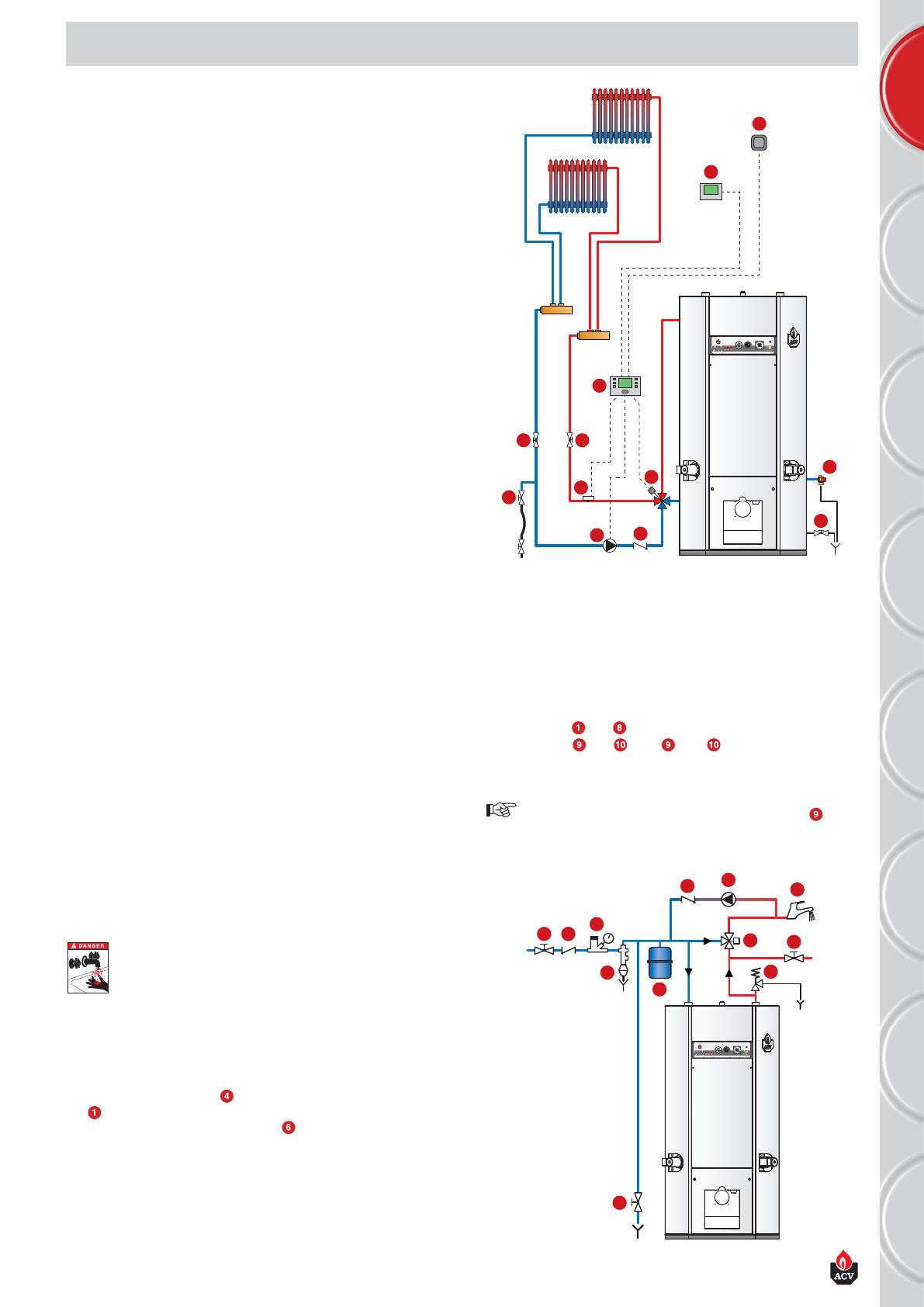
DRAINING THE HEATING CIRCUIT
1. Put the master switch of the control panel on OFF, isolate the
external electrical supply and turn off the gas or oil supply to the
boiler.
2. Close the isolating valves
or put manually the 4-way mixing valve
on “0”.
3. Connect a hose to the draining valve .
4. Open the draining valve to empty the primary circuit.
MAINTENANCE
I
O
2
7
3
9
1
8
10
11
4 4
5
6
9
10
7
8
6
2
11
5
1 2
3
4
I
O
DRAINING THE DHW CIRCUIT
1. Put the master switch of the control panel on OFF, isolate the
external electrical supply and turn off the gas or oil supply to the
boiler.
2. Release the pressure in the heating circuit until the pressure gauge
indicates 0 bar.
3. Close valves and .
4. Open valves and ( first then ).
5. Allow the drained water to flow into the sewer.
For the circuit to be drained, the draining valve must
be located at ground level.
DECLARATION OF CONFORMITY - EC
  • Page 1 1
  • Page 2 2
  • Page 3 3
  • Page 4 4
  • Page 5 5
  • Page 6 6
  • Page 7 7
  • Page 8 8
  • Page 9 9
  • Page 10 10
  • Page 11 11
  • Page 12 12
  • Page 13 13
  • Page 14 14
  • Page 15 15
  • Page 16 16
  • Page 17 17

ACV HeatMaster 200 N / 200 F (v13) : Operating instructions

Type
Operating instructions

Ask a question and I''ll find the answer in the document

Finding information in a document is now easier with AI