Page is loading ...

Hotspur 5 & 9 Issue 2 December 2017 1
Installation & Operating
Instructions
Covering Models:
Hotspur 5
Hotspur 9
Wood Burning Stoves
(Optional Coal Kit Available)
Tested to EN 13240
These appliances must be installed and commissioned by a HETAS registered engineer

Hotspur 5 & 9 Issue 2 December 2017 2
Contents
Introduction 3
Packing List 3
Health & Safety 4
Specifications 5
Dimensions 6
Hearth Requirements & Clearances 7
Chimney Requirements 9
Ventilation Requirements 11
Assembly
Smoke Control Area Specification 21
Internal Component’s 21
Controls Layout 22
Controls Explained 22
Appropriate Fuels 24
Lighting the Stove
Kindling Stage 25
Burning Wood & Burning Coal 26
Smoke Control Areas 27
Warning Notes 28
Maintenance
Ash Removal 29
Cleaning the Stove 29
Glass Cleaning 29
Chimney Sweeping 29
Chimney Fires 29
Stove Servicing 29
Trouble-shooting 30
Commissioning Form 31
Spare Parts 32
Annual Service Record 33
Product Fiche 34
Warranty 36

Hotspur 5 & 9 Issue 2 December 2017 3
Introduction
May we take this opportunity to thank you for choosing one of our stoves.
These appliances are designed to burn wood logs and wood derived fuels. It is essential that your wood
has been seasoned to ensure that it is sufficiently dry for burning. You can determine the moisture
content of your logs by using a digital moisture meter, your logs need to be below 20% moisture content
before they are considered dry enough for burning. Please note an optional kit is available which will
enable you to burn certain coals, this kit consists of a pair of refractory bricks (these bricks must be
present in the firebox at all times when burning coal).
Never burn wood that contains paint, glue or any other chemicals
See the section “Lighting the Stove” for further details. After reading this document, if there is anything
you are unsure about, please contact your dealer or our Technical Support Department.
These instructions cover the basic principles to ensure the satisfactory installation of the stove, although
detail may need slight modification to suit particular local site conditions. In all cases the installation must
comply with current Building Regulations, Local Authority Byelaws and other specifications or regulations
as they affect the installation of the stove.
It should be noted that the Building Regulations requirements may be met by adopting the relevant
recommendations given in British Standards BS 8303 and BS EN 15287-1 2007 + A1 2010 as an
alternative means to achieve an equivalent level of performance to that obtained following the guidance
given in Approved Document J.
Please note that it is a requirement under the Broseley Fires warranty system that the installation
of the stove is carried out by a Competent Person registered with a Government approved
Competent Persons Scheme. HETAS Ltd operate such a Scheme and a listing of their Registered
Competent Persons can be found on their website at www.hetas.co.uk.
Packing List
1x Steel Body stove 2x Vermiculite side firebricks (Left & Right)
1x Log retainer 2x Vermiculite rear firebrick (Lower & Upper)
1x Vermiculite Bottom Rear 2x Vermiculite Base Side (Left & Right)
1x Instruction booklet 2x Baffle (Main - Vermiculite & Top - Steel)
1x Heat Proof Glove 1x Cast Iron Grate
1x Top Outlet Spigot (Fitted) 1x Steel Ash pan
1x Air Intake Stub (Fitted) 1x Top Lid Blanking Plate (For rear outlet only –
Hotspur 5)
All parts will be inside the main stove body upon delivery. The spigot will generally be
bolted to the top of the stove body.
Optional Extras (With product codes)
S-HOTSPUR5/COAL & S-HOTSPUR9/COAL - Coal Kit for 5 & 9 kW Stoves
S-HOTSPUR5/RF - Rear flue outlet (Hotspur 5 Only)
S-DEAS/KIT/100 (Various Colours See page 10) - Direct External Air Supply (DEAS)

Hotspur 5 & 9 Issue 2 December 2017 4
Health & Safety
Special care must be taken when installing the stove such that the requirements of the
Health and Safety at Work Act are met.
Installation
This appliance MUST be installed and commissioned by a HETAS registered installer in
England and Wales and a fully qualified Heating Engineer in Scotland and Ireland.
Handling
Adequate facilities must be available for loading, unloading and site handling.
Fire Cement
Some types of fire cement are caustic and should not be allowed to come into contact
with the skin. In case of contact, wash immediately with plenty of water.
Asbestos
This stove contains no asbestos. If there is a possibility of disturbing any asbestos in the
course of installation then please seek specialist guidance and use appropriate
protective equipment.
Metal Parts
When installing or servicing this stove care should be taken to avoid the possibility of
personal injury.
CO Alarms
Building regulations require that whenever a new or replacement fixed solid fuel or
wood/biomass appliance is installed in a dwelling an audible carbon monoxide alarm
must be fitted in the same room as the appliance. Further guidance on the installation of
the carbon monoxide alarm is available in BS EN 50292:2002 and from the alarm
manufacturer’s instructions. Provision of an alarm must not be considered a substitute
for either installing the appliance correctly or ensuring regular servicing and
maintenance of the appliance and chimney system.
Fire Guards
When using the stove in situations where children, aged and/or infirm persons are
present a fireguard must be used to prevent accidental contact with the stove. The
fireguard should be manufactured in accordance with BS 8423:2002.
Aerosol Sprays
Do not use an aerosol spray on or near the stove when it is alight.
Operating Tool & Gloves
Always use the glove provided when handling parts likely to be hot when the stove is in
use. The handle and air controls will not get overly hot however it is still recommended
that the glove is used when operating these also. A poker or tool can be purchased
separately and does not come as standard with the stove.

Hotspur 5 & 9 Issue 2 December 2017 5
Specifications
In the UK these stoves have been approved by HETAS Ltd as intermittent heating
appliances for burning coal suitable for a closed appliance and wood logs only.
Hotspur 5
Hotspur 9
Nominal Heat Output (Wood) kW
5
9
Nominal Heat Output (Coal) kW
5
7
Efficiency (Wood) %
82
80
Efficiency (Coal) %
81 (Anthracite)
75 (Lignite)
Weight Kg
127
152
Flue Diameter mm
125
150
Flue Diameter Inches
5
6
Flue Draft Min Pa
12
12
Flue Draft Max Pa
18
18
Flue Temp (Wood) °C
253
298
Flue Temp (Coal) °C
205
328
CO Emission (@ 13% O
2
Wood) %
0.08
0.09
CO Emission (@ 13% O
2
Coal) %
0.40
0.09
Flue Mass Flow (Wood) g/s
4.3
4.2
7.0
6.6
Flue Mass Flow (Coal) g/s
Fuel Consumption Per Hour (Wood)
Fuel Consumption Per Hour (Coal)
1.10Kg
0.75Kg
2Kg
1.2Kg
Please note the figures above are taken from test house reports where the appliances
have been tested under strict EN13240 regulations.
European standards need to be complied to when installing this appliance.

Hotspur 5 & 9 Issue 2 December 2017 6
Dimensions
Hotspur 5
Hotspur 9

Hotspur 5 & 9 Issue 2 December 2017 7
Hearth Requirements & Clearances
These appliances are suitable for the minimal 12mm hearth's and do not require a
full constructional sub-hearth.
Your stove must be installed on a solid, level non-combustible hearth. The hearth
protrusion in front of the stove to carpets or wooden floors must be at least 300mm. As
it is possible, that on opening the door of the stove for fuel to fall out, a fender must be
fitted if the hearth is flush with the carpet.
Clearances
The stove requires the following minimum clearances around it to ensure the heat is
released into the room and to allow sufficient combustion air flow.
Product
Material
Rear
Side
Front
Above
Hotspur 5
Combustible
270mm
250mm
800mm
800mm
Non-combustible
50mm
100mm
300mm
100mm
Hotspur 9
Combustible
170mm
250mm
1200mm
1200mm
Non-combustible
50mm
100mm
300mm
100mm
Please note that for non-combustible materials the clearances are much lower. These
are minimum clearances and may not provide sufficient space in your installation to
provide adequate access for maintenance. Ideally you want as much space around the
product as possible to provide access at service intervals.
If fitting the stove in a non-combustible surrounding and using the 50mm rear clearance
it is very important to ensure the material used can withstand the heat being generated.
Cracking or discolouring may occur to some materials like tiles etc. It is also
recommended that if the stove is fitted with a rear clearance of 50mm, without DEAS
(Direct External Air Supply) fitted that the DEAS spigot on the back of the stove is
removed to aid air flow into the product.

Hotspur 5 & 9 Issue 2 December 2017 8
Hearth Requirements & Clearances
Installation options when fitting Hotspur 5 to Combustibles
Installation options when fitting Hotspur 9 to Combustibles

Hotspur 5 & 9 Issue 2 December 2017 9
Chimney Requirements
This appliance must not be fitted into a chimney serving another heating appliance. It is
most important that there is no obstruction in the flue or chimney. Please ensure that
any existing chimney is clear of obstruction and swept clean immediately before
installation of the new stove. If the chimney has been used for an open fire it is
recommended that it be swept for a second time having been used for a month
following installation.
A flue draught minimum of 12 Pascals to a maximum 18 Pascals is required for
satisfactory appliance performance. A properly built masonry or factory constructed
chimney (with a minimum vertical height of 5 metres) should ensure a consistent
draught (draw). 45° bends can be used in the flue run (maximum of four bends) you will
need to add an extra 1 metre of vertical flue height for each bend.
The flue draught should be checked under fire at high output and if it exceeds the
recommended maximum, a draught stabiliser must be fitted so that the rate of burning
can be controlled, and to prevent over firing (See section “Warning Notes”). If you have
any doubts about the suitability of your chimney, consult your local dealer/stockist or
engineer. If your flue draft is below the minimum recommendation then it may be
necessary to increase the vertical chimney height, add additional flue insulation or
possibly add a special cowl to the top of the chimney (e.g. anti down draft cowl to
eliminate wind induced down draft).
The outlet from the chimney should be above the roof of the building in accordance with
the provisions of Building Regulations Approved Document J.
If installation is into an existing chimney then it must be sound and have no cracks or
other faults which might allow fumes into the house. Older properties, especially, may
have chimney faults or the cross section may be too large i.e. more than 230 mm x 230
mm. Remedial action should be taken, if required, seeking expert advice, if necessary. If
it is found necessary to line the chimney then a flue liner suitable for solid fuel must be
used in accordance with Building Regulations Approved Document J.
If there is no existing chimney then either a prefabricated block chimney in accordance
with Building Regulations Approved Document J or a twin walled insulated stainless
steel flue to BS 4543 can be used. These chimneys must be fitted in accordance with
the manufacturer’s instructions and Building Regulations.
If a flexible liner is required the liner diameter must not be less than 5” / 125mm for the
HOTSPUR 5 and 6” / 150mm for the Hotspur 9.
Any bend in the chimney or connecting fluepipe should not exceed 45°. 90° bends are
not permitted. For top flue installations it is possible to sweep through the appliance by
removing the internal baffles however it is recommended that you provide adequate
access (e.g. easily accessible soot door). For rear flue connection we recommend the
use of a tee section, the bottom of the tee should be capped to catch soot and debris.

Hotspur 5 & 9 Issue 2 December 2017 10
Chimney Requirements
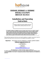
Rear Flue Installations – Using optional rear flue spigot (HOTSPUR 5 ONLY)
If fitting the appliance with a rear flue outlet, the top spigot will need to be replaced with
the optional reaf spigot (not supplied as standard). The optional rear spigot replaces the
top spigot and allows for a rear flue. It is recommended that only a 90 degree T flue
section is used directly out of the rear flue spigot. Access for cleaning the flue should
also be made available in the connecting vertical flue. The code for ordering the rear
flue spigot is S-HOTSPUR5/RF for Hotspur5
To fit the rear flue spigot you will first need to lift off the lid of the stove and then remove
the original top spigot. The sequence below will guide you through this process:
Step 1.
Remove the vermiculite baffle
Step 2.
Remove the square secondary metal
baffle that is adjacent the fitted spigot.
Step 3.
Loosen the 4 x Allen key bolts holding
the spigot in place.
Step 4.
Fit the new rear outlet spigot and
follow current sequence in reverse.
Note: The lid can be removed for easy viewing and spigot change over. Once the lid is
placed back on the stove, use blanking plate supplied to cover the hole left in the lid for
the top outlet spigot.

Hotspur 5 & 9 Issue 2 December 2017 11
Ventilation Requirements
In order for the stove to perform efficiently and safely there should be an adequate air
supply into the room in which the stove is installed to provide combustion air. This is
particularly necessary in modern houses where drafts have been almost eliminated by
double glazing etc.
Under UK building regulations any appliance over 5kW MUST have a fixed permanent
air vent (see building regulations approved document J for detailed information). The
following information is offered as a basic summary of the information found in Building
Regulations. This information should NOT be used as a substitute to following the full
requirements laid out in Building Regulations approved Document J.
Air Vent Calculation Hotspur 5
For new build properties you will need 5 x 550mm² = 2750mm²
Older properties do not normally need a vent.
Air Vent Calculation Hotspur 9
For new build properties you will need 9 x 550mm² = 4950mm²
Older properties you will need 4 x 550mm² = 2200mm²
There must not be an extractor fan fitted in the same room as the stove as this
can cause the stove to emit fumes into the room. It is necessary to install a wall
vent to provide the necessary combustion air and to prevent the depletion of
oxygen in the room.
Direct External Air Supply (DEAS)
The optional Direct External Air Supply eliminates drafts caused by traditional wall
vents. The DEAS will provide 100% of the operational combustion air.
The appliance has been designed and tested for safe when using a Broseley Fires
supplied DEAS Kit. It is therefore required that only the Broseley Fires DEAS Kit is used
when an external air supply is required.
When fitting the DEAS Kit the following comprehensive installation instructions must be
followed. It is important for the installing engineer to read these installation instructions
before commencing works on a DEAS installation and ensure the instructions for the
DEAS kit are understood as clear and concise.

Hotspur 5 & 9 Issue 2 December 2017 12
Ventilation Requirements
Only install a dedicated external air kit supplied or specified by Broseley Fires, and
which is installed in a way that meets all required provisions of the manufacturer’s
instructions, local Building Regulations requirements and appropriate standards. The
details and minimum specification below must be followed at all times. Broseley Fires
stocks the Direct External Air Supply Kit that suits this product. It can be purchased
directly. Its specific code when ordering is
O-DEAS/KIT/100/WHITE - White coloured outside ventilator
O-DEAS/KIT/100/TERRA - Terracotta coloured outside ventilator
O-DEAS/KIT/100/SAND - Buff/Sand coloured outside ventilator
O-DEAS/KIT/100/BROWN - Brown coloured outside ventilator
O-DEAS/KIT/100/BLACK - Black coloured outside ventilator
The kit contains the following:
1 x 6x6' Louvre Ventilator – available in White, Terracotta, Buff/Sand, Brown & Black
1 x 6x6' Louvre Back plate with 97mm Diameter Spigot
1 x 1.5m of Semi Rigid Aluminium Duct - 102mm (4 inches) Diameter
2 x 100mm Diameter Jubilee Clips
The minimum diameter of duct is 102mm (4 Inches)
The maximum total length of the duct is 1.5m
Assessment of the Property
Before any installation is carried out using a DEAS Kit the property must be fully
assessed to ensure there is enough ventilation (air-flow) available for combustion during
use and when the door is open for refuel. The following table gives advice on the
properties construction which can have an effect on its air permeability attributes. The
recommendations in this table should be used as a guide at all times.

Hotspur 5 & 9 Issue 2 December 2017 13
Age of Property
Refurbished
Type of Ventilation
Recommendation
Post 2008(Class 1)
NO
Significantly reduced energy demand due to air
tightness of the building. Typically double/triple
glazed windows with high levels of roof and
cavity insulation. Passive ventilation through
trickle vents and mechanical extracts in
kitchens/bathrooms.
Firstly follow building regs recommendation
on Air Permeability of the building. Special
attention needs to be made to any extractor
in the same room as the appliance eg: open
plan kitchen diner etc. DEAS Kit can be used
however a risk assessment and commission
testing needs to be carried out in
accordance with HETAS Technical Note
HETAS_TN_0020 v1.0. Extra ventilation
may be required.
Post 2008(Class 1)
House fitted with
Mechanical heat
Ventilation Recovery
System in same room
as appliance
NO
Significantly reduced energy demand due to air
tightness of the building. Typically double/triple
glazed windows with high levels of roof and
cavity insulation. Passive ventilation through
trickle vents and mechanical extracts in
kitchens/bathrooms. Special attention to
mechanical heat ventilation recovery systems is
required in this type of property construction.
Do Not Fit DEAS Kit
Between 1975-2008
(Class 2)
YES
Reduction to the original energy demand due to
improvements in properties air leakage. Typical
additions include double glazing, cavity wall and
loft insulation and draught proofing of
windows/doors. Typically passive ventilation
through trickle vents and mechanical extracts in
kitchens/bathrooms. Special attention to
mechanical heat ventilation recovery systems is
required in this type of property construction
Special attention needs to be made to any
extractor in the same room as the appliance
eg: open plan kitchen diner etc. DEAS Kit
can be used however a risk assessment and
commission testing needs to be carried out
in accordance with HETAS Technical Note
HETAS_TN_0020 v1.0. Extra ventilation
may be required.
If the property has mechanical heat recovery
Do Not Fit the DEAS.
Between 1975-2008
(Class 3)
NO
A large proportion of properties fall into this
category and the energy requirement of these
dwellings become greater due to higher heat
loss rates through the building fabric. They
normally have basic passive ventilation with
supplementary mechanical ventilation
incorporated. As the age of the property
increases, the amounts of insulation
incorporated decreases, leading to higher
leakage rates.
DEAS Kit can be used however a risk
assessment and commission testing needs
to be carried out in accordance with HETAS
Technical Note HETAS_TN_0020 v1.0.
Extra ventilation may be required.
Pre-1975 (Class 4)
YES
Old style housing with moderate/significant
improvements in the form of double glazing,
inclusion of cavity wall and loft insulation.
Addition of mechanical ventilation in the form of
extract fans in kitchens/bathrooms. Additional
improvements reduce the properties overall
energy requirement.
Special attention needs to be made to any
extractor in the same room as the appliance
eg: open plan kitchen diner etc. DEAS Kit
can be used however a risk assessment and
commission testing needs to be carried out
in accordance with HETAS Technical Note
HETAS_TN_0020 v1.0. Extra ventilation
may be required.
Pre-1975 (Class 4)
NO
Old style housing with single glazing with a high
energy requirement due to increased leakage
through the building structure. Typically basic
passive ventilation through vents in the wall/floor
and by opening of windows with no insulation or
additional draught proofing measures
incorporated.
DEAS Kit can be used. Commission testing
needs to be carried out in accordance with
HETAS Technical Note HETAS_TN_0020
v1.0.

Hotspur 5 & 9 Issue 2 December 2017 14
Ventilation Requirements
To carry out a risk assessment it will be necessary to grade the risks associated with
the property, including construction of property and ventilation. HETAS have designed a
risk assessment template that should accompany the table above and be completed at
all times.
It is not recommended that the fitting of the DEAS KIT is made into passive houses with
mechanical ventilation systems or extractors of any kind. In order for the stove to
perform efficiently and safely there should be an adequate air supply into the room in
which the stove is installed to provide combustion air. This is particularly necessary in
modern houses where drafts have been almost eliminated by double glazing etc. Fitting
the appliance into such properties requires
No possible means of air being taken from the room of the appliance eg:
Mechanical ventilation systems
Measures should be taken to ensure the air duct inlet does not become blocked
from snow, debris, and water ingress and not prone to collapse due to heat or
other effects.
The appliance fitted is to undergo stringent commissioning testing as set out in
HETAS Technical Note HETAS_TN_0020 v1.0 and detailed starting page 13.

Hotspur 5 & 9 Issue 2 December 2017 15
Ventilation Requirements
Fitting the DEAS KIT
Once suitable risk assessments have been performed the DEAS can be fitted to the
stove. Only Broseley Fires supplied kits should be used.
Step 1.
Using appropriate construction methods (for
the building material of your property) mark
andcut a 4 Inch/100mm diameter hole into the
external wall. Feed the semi rigid ducting
through the hole as pictured (right).
Step 2.
Feed 1 x Jubilee Clip over the opposite end of the duct pipe just fitted through the
external wall. Attach the pipe to the DEAS spigot already assembled on the stove.
Tighten the jubilee clip so the duct pipe is secure and sealed. When the connection is
made manoeuvre the stove into positon ensuring the duct is as straight as possible and
not containing any more than 2 bends.

Hotspur 5 & 9 Issue 2 December 2017 16
Ventilation Requirements
Fitting the DEAS KIT
Step 3.
Cut away any excess ducting. Feed the second Jubilee clip over the duct pipe (on the
external facing end). Attach the back plate to the duct pipe and tighten to form a tight
seal. Ensure jubilee clip is tightened in a position whereas it can be inserted into the
hole in the wall cavity leaving the back panel flush with the outer wall. Ensure unwanted
bends are not made in the duct pipe connecting the stove to the back plate.
Step 4.
Fix the back plate to the outside
wall. Screws and plugs to the
external wall are not included. It is
the fitter’s discretion in choosing
screws and fixings suitable for the
external surface. The back plate
should sit flush against the external
wall.

Hotspur 5 & 9 Issue 2 December 2017 17
Ventilation Requirements
Fitting the DEAS KIT
Step 5.
Finally screw the grille ventilator to
the back plate using the 4 x screws
supplied. As mentioned previously
it is important to ensure the air
duct ventilator does not become
blocked from snow or debris and to
prevent water and vermin ingress.

Hotspur 5 & 9 Issue 2 December 2017 18
Ventilation Requirements
Commissioning Testing
Once a suitable flue draught has been established, and to ensure that during start-up
operation and refuel that spillage does not occur, it is advised to carry out the following
3 step spillage test procedures and record the results using the On Site Verification of
HETAS Spillage Test Procedure Form.
Before commencing the commissioning process, it is important for the installer to
ensure the following have been met;
The installer has read and understood HETAS Technical Note HETAS_TN_0020
v1.0 and has taken account of the guidance contained within the appliance
manufacturer’s installation instructions.
A relevant risk assessment of the property and appliance has been carried out
The chimney, hearth and appliance is installed in accordance with the
requirements of ADJ and their suitability/soundness has been verified as
compliant
The air supply duct has been installed in accordance with the specification
detailed by the appliance manufacturer and within manufacturer instructions
A CO alarm has been fitted
Step 1 – Cold Spillage Test – Appliance Door Shut.
1. Close all external doors and windows, internal doors to the room the appliance is
located in and ensure all openable ventilators are closed and any devices that extract
air from the dwelling are off.
2. Preheat the flue by lighting a small fire using kindling, a blow lamp or electric heater.
3. Light a small smoke pellet (5m3/30 sec), place into the appliance and shut the
appliance door. All air-controls should be set to their maximum open position.
4. Check that all of the smoke enters the flue and none comes back into the room
through any part of the stove, connecting flue pipe or air supply duct.
Note: If visible smoke enters the room then repeat the flue preheat detailed in point 2
above, to generate additional flue draw. If the test still fails, progressively open a
window in the room the appliance is installed. If the flue starts to draw the smoke, this
will indicate a fault due to air starvation and the appliance is not being provided with
adequate air for the flue to function correctly. Note the additional area of ventilation
required and add permanently open ventilation into the room by that amount to correct
the problem.

Hotspur 5 & 9 Issue 2 December 2017 19
Ventilation Requirements
5. If applicable, correct any highlighted issues and re-test using steps 1-4 above. If
smoke continues to spill after opening a window, this indicates a more serious problem
(i.e. flue blockage) which much be addressed and then this commissioning process
repeated.
Step 2 - Extraction Test (Using a flue draught gauge)
A flue pressure testing device shall be fitted to the flue of the appliance.
1. Ensure all doors to the room and all external doors, windows and air vents designed
to be closable are closed, and all ventilation fans are switched off.
2. Light the appliance and allow for the optimum operating temperature to be reached
3. The flue draught reading should be recorded and checked that it is in the parameters
specified by the appliance manufacturer.
4. Open any internal doors interconnecting the room in which the appliance is installed
to rooms where extraction fans are present within the property
5. Turn on all extract fans within the property to the maximum speed setting allowed
6. Run the extract systems for ten minutes, and then, record the flue draught reading.
The reading should not be lower than the previous reading obtained with extracts
running and not fall below the parameters specified by the appliance manufacturer.
7. Once the tests confirm satisfactory operation, remove the test device and seal any
apertures in the flue way if required.
Note: If at any stage during commissioning the flue draught reading taken differs from
the draught parameters specified by the manufacturer, action should be taken to locate
the cause of the discrepancy and the installation rectified before proceeding with further
testing.
The extraction test is a means to verify that the manufacturer’s required flue draught
during operation is met under the relevant conditions. In some cases spillage can still
occur and so it is important to carry out the prescribed smoke spillage tests detailed
Step 3 – Hot Spillage Test - Refuelling
Now that initial chimney draw has been verified as adequate, light a fire in the appliance
using the recommended amount of kindling/small logs and manufacturer’s
recommended air control position and allow the appliance to reach its normal operating
temperature. At the end of the banking period and before refuelling;

Hotspur 5 & 9 Issue 2 December 2017 20
Ventilation Requirements
1. Close all external doors and windows, ensure all openable ventilators are closed.
2. Open the appliance door and with a smoke match/pen (15 sec burn time) pass over
the top and side edge of the opening of the combustion chamber, observe and record if
the smoke/combustion products are drawn into the chimney or spill back into the room.
Once the smoke is extinguished, close the appliance door
3. Repeat this test with all extraction fans running and internal doors open connecting
the room the appliance is installed in to the extraction device(s) (see extraction test
above)
Note: If smoke or combustion enters the room, then additional ventilation may be
required to compensate for the extraction device(s).This can be tested by gradually
opening a window and observing the relevant smoke patterns during operation.
If the smoke continues to fail to draw up the flue, or fails with additional ventilation
beyond that advised by ADJ Table 1, thoroughly inspect the flue/chimney and
termination for other faults.
Check the appliance/flue/chimney draw with a flue draught gauge and ensure draught is
within manufacturer’s guidelines. If no gauge is available, or no draught reading is
given, you can test with smoke as a “safety check” but there is no substitute for using
the correct tools and undertaking the correct tests
Commissioning is the final stage of an installation and intended to evidence that the
appliance works safely at the time the commissioning takes place. All dedicated
external air supply installations are subject to the relevant commissioning and site
testing provisions as required for under Building Regulations and are to be notified
through the HETAS CPS scheme, where a certificate of compliance is to be issued, a
copy retained by the installer and a copy left with the consumer for their records.
The commission procedure detailed above should be followed to confirm compliance for
DEAS appliances. Further supporting information on commissioning may be available
from recognised product specific manufacturer's instructions, and should be referenced
during the commissioning process.
A copy of the form should be left with the consumer and a copy retained by the installer
for their records
There must not be an extractor fan fitted in the same room as the stove as this can
cause the stove to emit fumes into the room. If the extractor fan is fitted within a large
open plan living area then the tests above should be carried out as a minimum.
Broseley Fires do not guarantee the appliance will pass its spillage test in such cases.
/