Charnwood Arc 5 Operating instructions
- Category
- Fireplaces
- Type
- Operating instructions
This manual is also suitable for

Operating & Installation Instructions
®


Ref. v1 07.16
C O N T E N T S
O P E R AT I N G I N S T R U C T I O N S
Fuel. . . . . . . . . . . . . . . . . . . . . . . . . . . . . . . . 5
Lighting. . . . . . . . . . . . . . . . . . . . . . . . . . . . . 6
. . . . . . . . . . . . . . . . . . . 6
Refuelling . . . . . . . . . . . . . . . . . . . . . . . . . . . 7
Ash Clearance . . . . . . . . . . . . . . . . . . . . . . . 7
Reduced Burning . . . . . . . . . . . . . . . . . . . . . 7
Maintenance . . . . . . . . . . . . . . . . . . . . . . . . . 7
Throat Plate & Flueway Clearing . . . . . . . . . 8
Chimney Sweeping . . . . . . . . . . . . . . . . . . . . 8
Trouble Shooting . . . . . . . . . . . . . . . . . . . . . 9
CO Alarm . . . . . . . . . . . . . . . . . . . . . . . . 9
If you need further help. . . . . . . . . . . . . . . 9
INSTALLATION INSTRUCTIONS
Health & Safety Precautions . . . . . . . . . . . .
CO Alarms . . . . . . . . . . . . . . . . . . . . . . . . .
Specification . . . . . . . . . . . . . . . . . . . . . . . .
Chimney . . . . . . . . . . . . . . . . . . . . . . . . . . .
Hearth & Fire Surround . . . . . . . . . . . . . . . 11
Connection to Flues . . . . . . . . . . . . . . . . . . 12
Soot Doors . . . . . . . . . . . . . . . . . . . . . . . . . 12
Pre Lighting Check . . . . . . . . . . . . . . . . . . . 12
Commissioning . . . . . . . . . . . . . . . . . . . . . . 13
. . . . . . . . . . . . . . . . . . . . 15
Multi Grate . . . . . . . . . . . . . . . . . . . . . . . . . . 5
Riddling . . . . . . . . . . . . . . . . . . . . . . . . . . . . 6
Controlling The Fire
Unpacking The Stove . . . . . . . . . . . . . . . . . 10
10
10
10
11
Clean Air Act Information. . . . . . . . . . . . . . 13
Certification . . . . . . . . . . . . . . . . . . . . . . . . 14
Dimensions Arc 5
Dimensions Arc 7 . . . . . . . . . . . . . . . . . . . . 16
Arc 5 Parts List . . . . . . . . . . . . . . . . . . . . . . 17
Arc 5 Low Stand Parts List . . . . . . . . . . . . . 18
Arc 7 Parts List . . . . . . . . . . . . . . . . . . . . . . 19
Arc 7 Low Stand Parts List . . . . . . . . . . . . . 20

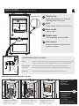
Add kindling and paper or
firelighters. Keep air control
fully out and close door
Once kindling is alight, add
smaller logs. Keep air control
fully out and close door
Add larger logs once fire is
established. Air control can
be reduced to medium
LIGHTING AND CONTROLLING THE FIRE
®
OPERATING INSTRUCTIONS
®
QUICK GUIDE
Your Charnwood at a glance
High
Output
Boost
Low
Output
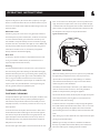
Throat plate
Improves efficiency of stove by
slowing down flue gases
a
b
Door
Keep closed when stove is in use
c
Door handle
Pull to open
Fuel retainer
Ensure fuel does not protrude
beyond retainer
d
b
a
c
e
d
Glass
Wipe with damp, lint free cloth.
removed with a proprietary stove glass cleaner or ceramic hob cleaner.
Any stubborn deposits on the glass may be
Throat plate
Take down once a month and clean. Sweep sooty deposits into fire.
Chimney
Have chimney swept twice a year. Chimney can be swept through stove.
Servicing
Stove should be serviced by a professional at least once a year.
MAINTENANCE AND CLEANING
Suitable fuels for your
Charnwood:
Wood logs
Smokeless Fuel
Unsuitable fuels:
Petroleum coke
Liquid fuel
Household waste
Coal singles
Small nuts or coal dust
Wet or unseasoned wood
p5
Riddler knob
Use operating tool to riddle
Air control
Operation Tool
p6
e

Wood logs
Only dry well seasoned wood should be burnt on this appliance as
burning wet unseasoned wood will give rise to heavy tar deposits in
the stove, on the glass and within the chimney. For the same reason
hard woods (such as Ash, Beech and Oak) are better than soft woods
(such as Pine and Spruce). Burning wet unseasoned wood will also
result in considerably reduced outputs. The wood should be cut and
split and then left to season in a well ventilated dry place for at least
one year but preferably two years before use. Approximate suitable
log sizes are:
180mm(7in) long and 75mm (3in) diameter
Log moisture content of <20% is recommended.
PETROLEUM COKE IS NOT SUITABLE FOR USE ON
THIS APPLIANCE. ITS USE WILL INVALIDATE THE
GUARANTEE.
This stove is not designed to burn household waste.
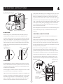
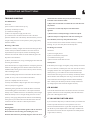
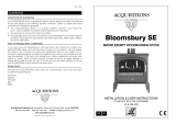
MULTI GRATE
Your Charnwood Arc is fitted with a multi grate to enable wood or
smokeless fuel to be burned and ash to be cleared. The grate has two
positions:
1) In the solid fuel position the grate bars are vertical with gaps in
between allowing the primary combustion air to come up through
the grate and through the fuel bed.
2) In the wood position the grate bars are horizontal, allowing the
combustion air to come round the sides of the grate and over the top
of it. When in the closed position ash is able to build up on the grate
as is necessary for effective wood burning.
Movement of the grate from one position to the other is effected
using the operation tool supplied as shown in Fig.1.
The grate is put into the solid fuel position by turning the operation
tool clockwise and pulling out the fuel selection lever Fig.1. The grate
is put into the wood position by turning the operation tool
anticlockwise and pushing the fuel selection lever in. To riddle the
appliance the tool should be moved between the clockwise and
anticlockwise positions several times. When burning wood the ash
should be allowed to build up and riddling should only be carried out
once or twice a week.
HETAS Ltd Appliance Approval only covers the use of Wood Logs
and Smokeless Fuels on this appliance.
Congratulations on becoming the owner of a Charnwood Arc Stove
Your stove has been approved in smoke control areas to burn wood
logs if it is used in accordance with these instructions. It is very
important that you read and understand these instructions before
using the stove.
.
FUEL
Before lighting the stove check with the installer that the work and
checks described in the Installation Instructions have been carried out
correctly and that the chimney has been swept, is sound and free
from any obstructions. The stove is not suitable for use in a shared
flue system.
Remember that the stove will be hot and that it is made from hard
materials – ensure that you have good balance before operating the
fire. Always use the provided operating tool and gloves.
Do not use an aerosol spray on or near the stove when it is alight.
There is a risk of explosion or flash ignition of the spray.
When using the stove in situations where children, aged and/or
infirm persons are present a fireguard must be used to prevent
accidental contact with the stove. The fireguard should be
manufactured in accordance with BS 8423:2002.
The stove is suitable for intermittent operation.
Please pay careful attention to the special points made with each type
of fuel as they will help you to get the best from your stove. It must
be remembered that only authorised fuels and wood logs may be
burnt in smoke control areas on this stove. If you are not sure
whether you are in a smoke control area, please check with your
Local Authority.
At first you may find it helpful to try several fuels to find the most
suitable. If you are unable to obtain the fuel you want, ask your
supplier, or an approved fuel distributor, to suggest an alternative.
Authorised Mineral Fuels
Authorised mineral fuels may be burned in smoke control areas on
this appliance. Your local fuel supplier or stove shop will be able to
advise you which fuels are available locally. A list of authorised fuels
can be found at:
Take care to only burn good quality fuels in order to obtain the
greatest efficiency and to maintain the life of the appliance.
https://smokecontrol.defra.gov.uk/fuels.php
®
OPERATING INSTRUCTIONS
5

RIDDLING
When burning wood, ash should be allowed to build up and only
riddled when the ash begins to cover the rear fireplate. The fire
should be riddled with the door shut (see Fig.2). Place the operating
tool onto the riddling lever and rotate between the open and closed
positions several times. Too much riddling can result in emptying
unburnt fuel into the ashpan and should therefore be avoided. After
riddling, the grate should be put back into the closed position for
burning wood.
On initial lighting, the stove may smoke and give off an odour as the
silicon paint with which the firebox is painted reacts to the heat. This
is normal and will cease after a short time, but meanwhile the room
should be kept well ventilated.
At first only light a small fire and burn it slowly for two hours to allow
any residual moisture in the chimney to evaporate.
Light the stove using dry kindling wood and paper or fire lighters. Put
the paper, or fire lighters, and kindling in the firebox and cover with a
few small dry logs. Open the air control fully (see Fig. 3). Light the
paper or fire lighters. The door may be left cracked open for a few
minutes to assist the combustion and heat up the firebox more
LIGHTING
quickly. When the kindling wood is well alight add a few more small
logs, close the door but leave the air control fully open. When the
flames are established around these logs, load the stove with the
required fuel load. Maintain the air control at maximum at this stage.
Once the fire is up to temperature the airwash system will begin to
work, so allow the fire to become hot before adjusting the air control
to the required setting. During the lighting period, do not leave the
stove unattended. Do not leave the door open except as directed
above to avoid excessive smoke.
When relighting the stove, leave the ash on the base if burning wood,
unless it is becoming too deep, in which case some of it may be
removed.
When the fire is burning normally the air control gives enough
airwash to keep the glass clean. However, it will not always be
possible to keep the glass clean with the air control fully closed. For
correct firing we recommend the use of a stove pipe thermometer
which may be purchased from your supplier or from Charnwood.
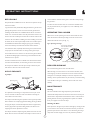
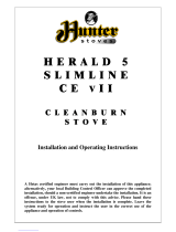
CONTROLLING THE FIRE
The rate of burning and hence the output is controlled by the air
control (see Fig.3).
Open the air control fully (boost position) when lighting or when
rapid burning is required. It should not be left fully open for long
periods as this can cause over-firing or excessive smoke production.
For high output move the air control to the ‘click position’ or for low
burning to the fully closed position.
The Charnwood Arc is fitted with an air control stop for use in a
smoke control area. This stops the stove from burning too slowly.
6
®
OPERATING INSTRUCTIONS
Air Control
Pull out to open
Push in to close
Door Handle
Pull to open
Riddler Knob
Identification Plate,
Lift Plate to View
High
Output
Boost
Low
Output
Fig. 3 S
tov
e controls
Fig.2 Riddling tool
Solid F
uel
W
ood
Fig.1 Operating the multi gr
ate
Pull le
ver out when burning solid fuel
W
ood
Solid Fuel

REFUELLING
ASH CLEARANCE
Keep the firebox well filled but do not allow fuel to spill over the top
of the fuel retainer.
Logs should be evenly distributed, filling the firebed to give the most
pleasing flame pattern. The air control must be fully opened after
refuelling until the flames are established above the fire. It is best to
refuel on to a hot bed of embers. If at this point the fire starts to die,
the door must be cracked open until the fire is revived. If the fire has
started to die down before refuelling, then more kindling wood must
be added, the air control opened fully and the door cracked open to
re-establish the firebed before adding larger logs (see suitable log
sizes in Fuel section). This will avoid excessive smoke emission.
Care should be taken, especially when burning wood, that fuel does
not project over the fuel retainer or damage to the glass may be
caused when the door is closed. It can also cause the glass to blacken
up. Maximum filling height is such that logs cannot fall from the fire
when the door is opened.
In smoke controlled areas do not fill the stove above the level of the
air holes in the back bricks, as overloading can cause excess smoke.
Do not operate with the door left open except as directed by the
instructions as this can cause excessive smoke.
For optimum wood burning, it is important to leave a layer of ash
around 1cm thick on the base of the stove. Before removing ash
ensure that it has cooled down,
The ashpan is handled using the operation tool and gloves provided.
Ensure that the tool is fully engaged before lifting (See Fig.4). When
carrying the ashpan, it should be kept horizontal and supported by
the carrying handle to prevent it falling off the tool. Please avoid
emptying hot ash into plastic liners or bins.
The Ashpan should be emptied regularly before it becomes too full.
Never allow the ash to accumulate in the ashpan so that it comes in
contact with the underside of the grate as this will seriously damage
the grate bars.
To make ash removal easier there are ash carriers available. These
may be purchased from your supplier or, in case of difficulty, from
Charnwood.
When not in use the operating tool can be stored inside the store
stand. On the low model the operating tool can be stored on the
shelf underneath the stove. (See fig. 5.)
For reduced burning the fire door must be closed.
When burning wood in areas that are not smoke controlled, load
some large logs on the fire and allow to burn for half an hour before
closing the air control (this will help to reduce tar deposits in the
chimney). Some experimentation may be necessary to find the setting
most suitable for the type of fuel being used and the draw on the
chimney.
Cleaning
Cleaning the Glass
OPERATING TOOL HOLDER
REDUCED BURNING
MAINTENANCE
The stove is finished with a high temperature paint which will
withstand the temperatures encountered in normal use. This may be
cleaned with a damp lint-free cloth when the stove is cold. Should re-
painting become necessary, high temperature paints are available
from your supplier or from stove shops.
Most deposits on the glass may be burnt off simply by running the fire
at a fast rate for a few minutes. If it becomes necessary to clean the
glass then open the door and allow it to cool. Clean the glass using a
damp cloth and then wiping over with a dry cloth. Any stubborn
7
®
OPERATING INSTRUCTIONS
Operating Tool
Extra carrying handle
Use with glove
Fig.4 Ashpan
Fig. 5. Operating tool storage
Tool storage underneath
stove on left hand side
(Arc 5 Low only)
Tool storage inside store stand (Arc 5 & 7)

tubes. To return the lower throat plate to its correct position- At an
angle, insert the throat plate so that it sits on top of either the right
or left side brick. Raise the opposite side and slide so that the throat
plate is central and supported by both side bricks. Slide back so that
the throatplate rests neatly on the top of the back bricks.
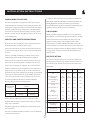
Where the chimney previously served an open fire, it is possible that
the higher flue gas temperature from a stove may loosen soot
deposits with the consequent risk of flue blockage. It is therefore
recommended that the chimney be swept a second time within a
month of regular use after installation.
The chimney should be swept at least twice a year. Where the top
outlet or vertical rear flue connector is used it will generally be
possible to sweep the chimney through the appliance.
First remove the fuel retainer, the throat plate and upper throat plate.
Then sweep the chimney ensuring that soot is removed from all
horizontal surfaces after sweeping.
In situations where it is not possible to sweep through the appliance
the installer will have provided alternative means, such as a soot door.
After sweeping the chimney the appliance flue outlet and the flue
pipe connecting the stove to the chimney must be cleaned with a flue
brush.
After clearing any soot from within the stove, replace the throat plate
(see Fig. 6) and the fuel retainer.
CHIMNEY SWEEPING
Different types of sweep’s brushes are available to suit different
flueways. For prefabricated insulated chimneys the manufacturers
instructions with regard to sweeping should be consulted.
deposits on the glass may be removed with a proprietary stove glass
cleaner or ceramic hob cleaner. Do not use abrasive cleaners or pads
as these can scratch the surface which will weaken the glass and cause
premature failure
After long periods
where the fire has been out of use, the chimney and appliance
flueways should be cleaned before lighting.
It is important that the upper and lower throat plates and all the stove
flueways are kept clean in order to prevent potentially dangerous
fume emission. They should be cleaned at least monthly, and more
frequently if necessary. It is necessary to let the fire out to carry out
these operations.
To remove the lower throat plate, slide it forwards so that it clears
the back brick, then slide it either right or left so that the opposite
side clears the top of the side brick and can be gently lowered. The
upper throat plate can then be located and rests on top of the air
wash tubes (fig.6). Any sooty deposits should then be swept from
both plates and into the fire.
First return the upper throat plate to its location above the air wash
When Not in Use
If the fire is going to be out of use for a long period (for instance in
the summer) then to prevent condensation, and hence corrosion, the
air control should be left fully open and the fire door left ajar. It Is
also advisable to sweep the chimney and clean out the fire. Spraying
the inside of the door and firebox with a light oil, such as WD40, will
also help to keep all internal parts working well.
Door Seals
For the fire to operate correctly it is important that the door seals
are in good condition. Check that they do not become worn or
frayed and replace them when necessary.
Servicing
It is recommended that the fire is serviced once a year to keep it in
first class working order. After cleaning out the firebox thoroughly,
check that all internal parts are in good working order, replacing any
parts that are beginning to show signs of wear. Check that the door
seals are in good condition and that the door seals correctly. A
servicing guide is available on request. Repairs or modifications may
only be carried out by the Manufacturer or their approved agents.
Use only genuine Charnwood replacement parts.
THROAT PLATE AND
FLUEWAY CLEANING
8
®
OPERATING INSTRUCTIONS
Side view
Upper Throat Plate
Throat Plate
Fig.6 Throat Plate Location

TROUBLE SHOOTING
Fire Will Not Burn
Check that:
a) the air inlet is not obstructed in any way,
b) chimneys and flueways are clear,
c) a suitable fuel is being used,
d) there is an adequate air supply into the room,
e) an extractor fan is not fitted in the same room as the stove.
f) there is sufficient draw in the chimney. Once the chimney is warm a
draught reading of at least 1.25 mm (0.05 in.) water gauge (12Pa)
should be obtained.
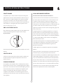
Blackening of Door Glass
Differences in chimney draughts mean that the best settings of the air
controls will vary for different installations. A certain amount of
experimentation may be required, however the following points
should be noted and with a little care should enable the glass to be
kept clean in most situations:
a) Wet or unseasoned wood, or logs overhanging the front fence will
cause the glass to blacken.
b) The airwash relies on a supply of heated air to keep the glass clean,
therefore, when lighting the stove allow the firebed to become well
established before closing the air control. This may also be necessary
when re-fuelling the stove.
c) When re-fuelling keep the fuel as far back from the front fence as
possible, do not try to fit too much fuel into the firebox.
d) Do not completely close the air control.
It is always more difficult to keep the glass clean when running the
stove very slowly for long periods.
If blackening of the glass still occurs check that all flue connections
and the blanking plate are well sealed. It is also important that the
chimney draw is sufficient and that it is not affected by down-draught.
When the chimney is warm a draught reading of at least 1.25 mm
(0.05 in.) water gauge (12Pa) should be obtained. Some blackening
of the glass may occur below the level of the fuel retainer. This will
not obscure the view of the fire or affect its performance.
Fume Emission
Warning Note:
Properly installed and operated this appliance will not emit fumes.
Occasional fumes from de-ashing and re-fuelling may occur.
Persistent fume emission is potentially dangerous and must not be
tolerated. If fume emission does persist, then the following
immediate actions should be taken:
a) Open doors and windows to ventilate the room and then leave
the premises.
b) Let the fire out and safely dispose of the fuel from the
appliance.
c) Check for flue or chimney blockage, and clean if required.
d) Do not attempt to re-light the fire until cause of fuming has
been identified, if necessary seek professional advice.
The most common cause of fume emission is flueway or chimney
blockage. For your own safety these must be kept clean.
Fire blazing out of control
Check that:
a) The door is tightly closed.
b) The air control slider is fully closed.
c) A suitable fuel is being used.
d) Door seals and airwash slide are intact.
Chimney Fires
If the chimney is thoroughly and regularly swept, chimney fires should
not occur. However, if a chimney fire does occur close the air control,
and tightly close the door of the appliance. This should cause the
chimney fire to go out in which case the controls should be kept
closed until the stove has gone out. The chimney and flueways should
then be cleaned. If the chimney fire does not go out when the above
action is taken then the fire brigade should be called immediately.
After a chimney fire the chimney should be carefully examined for
any damage. Expert advice should be sought if necessary.
CO ALARM
Your installer should have fitted a CO alarm in the same room as the
appliance. If the alarm sounds unexpectedly, follow the instructions
given under “Warning Note” above.
IF YOU NEED FURTHER HELP
If you need further help with your Charnwood then your Installer will
be able to provide the answers to most questions. Your Local
Charnwood Premier Dealer has a great deal of experience and will
also be able to provide helpful advice. Further help is available from
the Charnwood Customer Services department who will be pleased
to give advice, if necessary.
9
®
OPERATING INSTRUCTIONS

UNPACKING THE STOVE
The stove arrives bolted and strapped to its pallet. There must be
adequate facilities for unloading and manoeuvring into position The
wrapping is first removed, then the stove released from the pallet by
removing 4 pallet bolts using a 10mm spanner. The pallet brackets
can now be removed from the stove by tilting it and using a 13mm
spanner to remove the bolts. The pallet is intended to be cut up and
used for kindling fuel.
Please take care when installing the stove that the requirements of
the Health and Safety at Work Act 1974 are met.
HEALTH AND SAFETY PRECAUTIONS
Some types of fire cement are caustic and should not be allowed to
come into contact with the skin. In case of contact wash with plenty
of water.
If there is a possibility of disturbing any asbestos in the course of
installation then please use appropriate protective equipment.
There must not be an extractor fan fitted in the same room as the
stove as this can cause the appliance to emit fumes into the room.
There must be an adequate air supply into the room in which the
appliance is installed to provide combustion air. The combustion air
supply must be via a permanently open vent. The requirement for
minimum free area is partly dependent on the design air permeability
of the house. In older properties the air permeability will be above
5.0m³/(h.m²), but in some modern properties it may be less. The
vent must be positioned such that it is not liable to blockage.
Minimium areas are given in the following table:
A fixed ducted air supply may be used as an alternative to the
traditional method of using a permanent open vent into a room to
supply air for combustion.
External air supply kits are available please contact Charnwood for
more information.
This stove is capable of intermittent operation, and is not suitable for
use in a shared flue system.
10
®
INSTALLATION INSTRUCTIONS
In addition to these instructions the requirements of BS.8303 and
BSEN 15287-1:2007 must be fulfilled. Local Authority Bylaws and
Building Regulations, including those referring to national and
European Standards, regarding the installation of Solid Fuel burning
appliances, flues and chimneys must also be observed.
CO ALARMS
Building regulations require that whenever a new or replacement
fixed solid fuel or wood/biomass appliance is installed in a dwelling a
carbon monoxide alarm must be fitted in the same room as the
appliance. Further guidance on the installation of the carbon
monoxide alarm is available in BS EN 50292:2002 and from the
alarm manufacturer's instructions. Provision of an alarm must not be
considered a substitute for either installing the appliance correctly or
ensuring regular servicing and maintenance of the appliance and
chimney system.
The outputs in the table are based on a 45 minute re-fuelling cycle
burning seasoned hardwood logs. Solid fuel results are based on a 1
hour refuelling cycle. All tests are carried out in accordance with
BSEN 13240.
SPECIFICATION
Specification
Arc 5
Arc 5
Arc 7
Arc 7
Fuel
Wood
Logs
Smokeless
Fuel
Wood
Logs
Smokeless
Fuel
Nominal Heat Output
kW (BTU/hr)
5.0
(17,000)
5.0
(17,000)
7.5
(25,590)
7.7
(26,270)
Low Stove Weight kg
(Packed)
130
130
150
150
Store Stand Stove Weight kg
(Packed)
150
150
170
170
Flue Temperature °C
269
294
304
308
Minimum
Flue Draught
12Pa
12Pa
12Pa
12Pa
Flue gas Mass Flow g/s
4.4
3.4
5.3
5.7
Hearth Temperature °C
<100
<100
<100
<100
Side
Back
Side
Back
Minimum distance from
combustibles mm
Insulated Flue
270
80
270
150
Minimum distance from
combustibles mm
Uninsulated Flue
300
200
270
357
Air Permeability
m³/(h.m²)
Minimum Vent Area
cm²(in²)
Arc 5
Arc 7
> 5.0
No requirement
11 (1.76)
<5.0
27.5 (4.3)
38.5 (6.0)

CHIMNEY
HEARTH AND FIRE SURROUND
In order for the appliance to perform satisfactorily the chimney height
must not be less than 4 metres measured vertically from the outlet of
the stove to the top of the chimney. The internal dimensions of the
chimney should preferably be 150-200 mm (6"- 8") either square or
round and MUST NOT BE LESS THAN 125 mm (5") - Arc 5, 150
mm (6") - Arc 7.
If an existing chimney is to be used it must be swept and checked, it
must be in good condition, free from cracks and blockages, and
should not have an excessive cross sectional area. If it was previously
used by an open fire then the chimney should be swept one month
after installation to clear any soot falls which may have occurred due
to the difference in combustion between the stove and the open fire.
If you find that the chimney is in poor condition then expert advice
should be sought regarding the necessity of having the chimney lined.
If it is found necessary to line the chimney then a lining suitable for
Solid Fuel must be used.
If there is no existing chimney then a prefabricated block chimney or
a twin walled insulated stainless steel flue to BSEN 15287-1:2007 can
be used either internally or externally. These chimneys must be fitted
in accordance with the manufacturers instructions and Building
Regulations.
Single wall flue pipe is suitable for connecting the stove to the
chimney but is not suitable for using for the complete chimney. If it is
found that there is excessive draw in the chimney then a draught
stabiliser should be fitted.
It is important that there is sufficient draw in the chimney and that
the chimney does not suffer from down-draught. When the chimney
is warm the draw should be not less than 1.25mm (0.05") water
gauge (12 Pa). If in doubt about the chimney seek expert advice.
The stove must stand on a fireproof hearth and must not be situated
closer than the minimum distance from combustible materials (see
specification table) to the sides or rear above hearth level unless
adequately fireproofed in accordance with local building regulations.
The hearth must be of fireproof material and at least 12mm (1/2in.)
thick. The positioning of the stove and the size of the hearth are
governed by building regulations for Class 1 appliances. These
building regulations state that the hearth must extend in front of the
stove by at least 225mm (9 in.) and to the sides of the stove by at
least 150mm (6 in.). When the fire door is open, it extends beyond
the flat front of the stove by 436mm - Arc 5, 450mm - Arc 7.
If in doubt as to the positioning of the stove, expert advice should be
sought either from the supplier or the local building inspector. The
fireplace must allow good circulation of air around the appliance to
ensure that maximum heat is transferred to the room and also to
prevent the fireplace from overheating. A gap of 150mm (6") each
side and 300mm (12") above the appliance should give sufficient air
circulation. If a wooden mantelpiece or beam is used in the fireplace it
should be a minimum of 460mm (18"), and preferably 600mm (24")
from the appliance. In some situations it may be necessary to shield
11
®
INSTALLATION INSTRUCTIONS
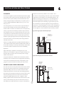
Alternative
Soot Door
Positions
Register Plate
With Soot Door
Register Plate
Soot Door
in side or rear
of Chimney
Fig.7. Vertical register plate with bricked up fireplace
Fig.8. Horizontal register plate with rear flue connection

12
®
INSTALLATION INSTRUCTIONS
the beam or mantelpiece to protect it.
In order for the fire to operate correctly and to allow for access,
there must be an air gap behind the appliance of at least 50mm, but
be aware that this distance will need to be greater in some cases to
meet Building Regulation requirements.
The appliance should be installed on a floor with adequate load-
bearing capacity. If an existing construction does not meet this
requirement then please take suitable measures to achieve this. (e.g.
load distributing plate.)
Fig. 9. Horizontal register plate with top flue connection
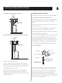
CONNECTIONS TO FLUES
The top outlet connection is made
directly to the cast top of the Arc 7 model, the Arc 7 is supplied with
a flue collar for rear outlet installations.
The stove must be connected to the flue using flue pipe of 125mm
(5") diameter - Arc 5, 150mm (6") diameter - Arc 7.
If the top flue connection or optional vertical rear flue connector is
used then the chimney may be swept through the appliance.
Horizontal lengths of flue must be kept to a minimum and should not
be more in length than the flue diameter.
The stove comes with the blanking plate (fig. 11) fitted to the top flue
outlet. The seal for the top outlet is a 155mm dia ring of rope seal.
The seal for the rear outlet is a length of adhesive backed fibre
webbing supplied with instructions. This is applied to the flue collar or
the Vertical Rear Flue adapter for rear outlet installations. For top
outlet installations, the blanking plate must be removed, have the
webbing fitted to its sealing face, and fitted to the rear flue outlet.
This may be stainless steel, cast iron, or thick wall steel pipe. Straight
lengths of Charnwood Pipe to match the stove are available if
required.
There are several ways of connecting the stove to the flue. These are
illustrated in Figs. 7 to 10.
Ensure that the fold on the clamping plate is in line with the lugs on
the firebox as shown in Fig 11. Ensure that the clamping plate does
not prevent the throat plate from seating correctly. All flue
connections must be well sealed.
Alternative
Soot Door
Positions
Register Plate
With Soot Door
Alternative
Soot Door
Positions
Register Plate
With Soot Door
Fig. 10. Horizontal register plate with optional vertical rear flue connector
Fig. 11. Flue Blanking Plate.
Blanking Plate
Glass Fibre Webbing
Seal Blanking Plate with
Glass Fibre Webbing
Blanking Plate
Back of Stove
Clamping Plate
M8 Nut
Clamping plate finishes
flush with the inside face
of the firebox top and
bottom.

13
®
INSTALLATION INSTRUCTIONS
SOOT DOORS
PRE LIGHTING CHECK
HEAT SHIELD
COMMISSIONING
It is possible to pass a 16 inch diameter sweeps brush through the
appliance but in most back outlet installations it will be necessary to
have a soot door to enable the chimney to be swept. The optional
vertical rear flue connector does allow the chimney to be swept
through the stove. Soot doors may either be in the actual brickwork
of the chimney or in the register plate. Various positions of soot
doors are shown in Figs. 7 to 10.
Ensure that the throat plate is fitted in the roof of the appliance. The
location and positioning of the throat plate is shown in Fig. 6.
Check that the front fence is fitted correctly and that the door closes
properly.
If removed, ensure that the slots in the heat shield are refitted over
the tabs on the left and right hand side panels into the correct
position see fig. 12.
On completion of the installation allow a suitable period of time for
the fire cement and mortar to dry out before lighting the fire. Make a
layer of ash or sand on the base of the stove before lighting. Check to
ensure that smoke and fumes are taken from the appliance up the
chimney and emitted safely. Also check all joints and seals. On
completion of the installation and commissioning please leave the
operating instructions with the customer and advise them on the use
of the appliance.
CAA AND SMOKE CONTROL
The Clean Air Act 1993 and Smoke Control Areas
Under the Clean Air Act local authorities may declare the whole or
part of the district of the authority to be a smoke control area. It is
an offence to emit smoke from a chimney of a building, from a
furnace or from any fixed boiler if located in a designated smoke
control area. It is also an offence to acquire an "unauthorised fuel" for
use within a smoke control area unless it is used in an "exempt"
appliance ("exempted" from the controls which generally apply in the
smoke control area).
In England appliances are exempted by publication on a list by the
Secretary of State in accordance with changes made to sections 20
and 21 of the Clean Air Act 1993 by section 15 of the Deregulation
Act 2015. Similarly in Scotland appliances are exempted bypublication
on a list by Scottish Ministers under section 50 of the Regulatory
Reform (Scotland) Act 2014.
In Northern Ireland appliances are exempted by publication on a list
by the Department of Agriculture, Environment and Rural Affairs
under Section 16 of the Environmental Better regulation Act
(Northern Ireland) 2016.
In Wales appliances are exempted by regulations made by Welsh
Ministers.
Further information on the requirements of the Clean Air Act can be
found here: https://www.gov.uk/smoke-control-area-rules
Your local authority is responsible for implementing the Clean Air Act
1993 including designation and supervision of smoke control areas
and you can contact them for details of Clean Air Act requirements.
The Arc 5 Store Stand and Arc 5 Low have been recommended as
suitable for use in smoke control areas when burning wood logs.The
models include factory-fitted
modifications to the air controls which have been designed to meet
Clean Air Act requirements for smoke control Exemption
The Arc 5 Store Stand and Arc 5 Low
Fig. 12. Heat shield

14
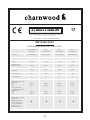
EN13240:2001
ROOMHEATERS FIRED BY SOLID FUEL
A Division of A.J.Wells & Sons Limited Registered in England No. 03809371
17
Bishops Way, Newport, Isle of Wight PO30 5WS, United Kingdom
A.J WELLS & SONS LTDA.J WELLS & SONS LTD
CE Certificate for compliance with EN13240:2001
ARC 5 STORE STAND
ARC 5 LOW
ARC 5
ARC 5 LOW
ARC 7
ARC 7 LOW
ARC 7
ARC 5 LOW
EC Certificate of
conformity no:
EZ44-CPD-2016
EZL44-CPD-2016
EZ44-CPD-2016
EZL44-CPD-2016
KZ44-CPD-2016
KZL44-CPD-2016
KZ44-CPD-2016
KZL44-CPD-2016
Fuel type:
WOOD LOGS
SOLID FUEL
WOOD LOGS
SOLID FUEL
Space heating thermal
output:
5 kW
5 kW
7 kW
7 kW
Emission of CO in
combustion products:
0.08%
0.07%
0.07%
0.05%
Mean flue gas
temperature:
269°C
294°C
304°C
308°C
Energy efficiency:
81%
82%
81%
79%
3
Particles (mg/m )
n
22
34
24
30
Minimum distance to
combustible materials with
Insulated flue
Side:
Rear:
Minimum distance to
combustible materials with
Uninsulated flue
Side:
Rear:
270mm
80mm
300mm
200mm
270mm
80mm
300mm
200mm
270mm
150mm
270mm
357mm
270mm
150mm
270mm
357mm
Fulfilled requirements:
BStV of the City of Munich
and the City of
Regensburg FBStVO of
the City of Aachen and
the City of Düsseldorf
1.and 2. level of 1.
BlmSchV of Germany

®
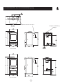
DIMENSIONS (mm)CHARNWOOD ARC 5
15
Store Stand Model
Low Stand Model
Optional vertical rear flue adaptor
133 i/d to suit 125mm (5")
flue pipe
983
933
783
733
163
458

®
DIMENSIONS (mm)CHARNWOOD ARC 7
516
138
169
455
493
502
1040
1023
159
449
311
832
493
502
449
815
159
79
98
79
894
686
Optional vertical rear flue adaptor
Store Stand Model
Low Stand Model
16
156 i/d to suit 150mm (6")
flue pipe

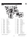
Item Part No. Description Item Part No. Description
1* 008/FW29 Door Seal Adhesive
38 008/FFW007 M10 Washer
2 006/EZ018 Glass Inc. Seal
39 010/EZ058 Lock Linkage/ Lower Latch
3 008/EZ002 Door Rope
40 010/EZ060 Door Latch Spacer
4 004/EZ023 Glass Retainer
41 008/FFW029 M10 Brass Washer
5 011/EZ029S Fire Brick Set (4)
42 002/EZ066 Door Handle (Cast)
6 011/EZ031 Brick Throat Plate
43 010/EZ055 Lower Latch Plate
7 010/EZ032 Upper Baffle Plate
44 010/EZ065 Latch Mounting Plate
8 010/ER036 Brick Retaining Washer
45 002/EZ053 Lower Hinge Bracket
9 008/FFB125 Coach Bolt M6 x 45
46 002/EZ054 Upper Hinge Bracket
10 004/XV30 Brick Bracket
47 010/EZ034 Slider Air Control Backing plate
11 002/CG23 Driving Grate Bar
48 004/EZ033 Wood/Multifuel Surround plate
12 002/CG01S5 Set of Grate Bars (5)
49 004/EZ035 Slider Wood/Multifuel
13 010/EZ013 Undergrate Ash Deflector
50 004/EZ014 Wood/Multifuel Selection Lever
14 010/EZ080 Rear Fire Plate
51 008/EZ006 Airbox Gasket
15 010/EZ079 Side Fire Plate
52 004/EZ020 Air Control Slider
16 012/SY33 Mover Bar
53 004/BR015 Clicker Retainer Plate
17 002/SY30C LH Carrier Bar
54 008/ES36/01 Brass Ball Catch
18 002/EZ077 RH Carrier Bar
55 012/EZ016 Control Rod
19 012/CG05 Idler Rod
56 012/EZ105 Air Control Handle
20 002/EZ098 Riddler Knob
57 008/BR052 Felt Washer
21 002/EZ007 Front Fence
58 004/BR054 Blanking Plate
22 004/EZ017 Ashpan Assembly
59 008/BR044 Gasket Blanking Plate
23* 008/NV38 Flue Fixing Rope Seal
60 004/EZ040 Air Box Cover
24 012/PV09 Blanking Plate
61 008/FFS062 Defra Stop
25 010/EY51 Clamping Plate
62 008/BR053 Air Inlet Spigot
26 002/PV12B Flue Collar
63 002/EZ063 Door Hinge Bracket
27 002/EZ009 Cast Top
64# 001/EZ010 Firebox
28 010/EZ012 Top Retaining Bracket
65 012/EZ011 Serial Label
29 010/EZ003 Door Back Plate
66# 004/EZ093L Left Side Panel
30 004/EZ004 Door Rope Channel
67# 004/EZ093R Right Side Panel
31 004/EZ097 Horizontal Door Rope Channel
68 010/EZ099 Stand Baseplate
32# 002/EZ001/A Door Assembly
69# 002/EZ071 Store Stand Casting
33 010/EZ061 Receiver Plate Upper
70 004/EZ078 Stand Backplate
34 008/FFS084 M5 x 8 Button Hd Allen Screw
71# 004/EZ102 Store Stand Lower Heatshield
35 008/FFW016 M5 Shakeproof Washer
72 004/EZ101 Upper Heatshield Inner Skin
36 010/EZ059 Upper Latch
73# 004/EZ103 Upper Heatshield
37 008/FFW027 M10 Wavy Washer
74# 010/PV33 Vertical Rear Flue Adapter
75 012/EZ095 Riddler/ Ashpan Operation Tool
* These items are not shown on the drawing
# Please specify colour when ordering.
To obtain spare parts please contact your local stockist
giving Model, Part No. and Description. In case of
difficulty contact the manufacturer at the address
shown.
This drawing is for identification purposes only.
Issue A
®
CHARNWOOD ARC 5 STORE STAND PARTS LIST
74
71
70
66
60 59 58 57
59
61
62
52
56
51
48
49
47
63
63
24
25 65
64
26
27
7
6
5
10
5
5
6922
32
4443
33 36
40
39
13
15
12
19
18
11
15
75
45
46
68
10
5
73
16
3
2
4
89
20
21
14
19
28
2930 3031
34 35
38
37
41
42
50
53
54
55
67
72
38
17

Issue A
®
CHARNWOOD ARC 5 LOW PARTS LIST
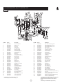
Item Part No. Description Item Part No. Description
1* 008/FW29 Door Seal Adhesive
38 008/FFW007 M10 Washer
2 006/EZ018 Glass Inc. Seal
39 010/EZ058 Lock Linkage/ Lower Latch
3 008/EZ002 Door Rope
40 010/EZ060 Door Latch Spacer
4 004/EZ023 Glass Retainer
41 008/FFW029 M10 Brass Washer
5 011/EZ029S Fire Brick Set (4)
42 002/EZ066 Door Handle (Cast)
6 011/EZ031 Brick Throat Plate
43 010/EZ055 Lower Latch Plate
7 010/EZ032 Upper Baffle Plate
44 010/EZ065 Latch Mounting Plate
8 010/ER036 Brick Retaining Washer
45 002/EZ053 Lower Hinge Bracket
9 008/FFB125 Coach Bolt M6 x 45
46 002/EZ054 Upper Hinge Bracket
10 004/XV30 Brick Bracket
47 010/EZ034 Slider Air Control Backing Plate
11 002/CG23 Driving Grate Bar
48 004/EZ033 Wood/Multifuel Surround Plate
12 002/CG01S5 Set of Grate Bars (5)
49 004/EZ035 Slider Wood/Multifuel
13 010/EZ013 Undergrate Ash Deflector
50 004/EZ014 Wood/Multifuel Selection Lever
14 010/EZ080 Rear Fire Plate
51 008/EZ006 Airbox Gasket
15 010/EZ079 Side Fire Plate
52 004/EZ020 Air Control Slider
16 012/SY33 Mover Bar
53 004/BR015 Clicker Retainer Plate
17 002/SY30C LH Carrier Bar
54 008/ES36/01 Brass Ball Catch
18 002/EZ077 RH Carrier Bar
55 012/EZ016 Control Rod
19 012/CG05 Idler Rod
56 012/EZ105 Air Control Handle
20 002/EZ098 Riddler Knob
57 008/BR052 Felt Washer
21 002/EZ007 Front Fence
58 004/BR054 Blanking Plate
22 004/EZ017 Ashpan Assembly
59 008/BR044 Gasket Blanking Plate
23* 008/NV38 Flue Fixing Rope Seal
60 004/EZ040 Air Box Cover
24 012/PV09 Blanking Plate
61 008/FFS062 Defra Stop
25 010/EY51 Clamping Plate
62 008/BR053 Air Inlet Spigot
26 002/PV12B Flue Collar
63 002/EZ063 Door Hinge Bracket
27 002/EZ009 Cast Top
64# 001/EZL010 Firebox
28 010/EZ012 Top Retaining Bracket
65 012/EZL011 Serial Label
29 010/EZ003 Door Back Plate
66# 004/EZL091L Left Side Panel
30 004/EZ004 Door Rope Channel
67# 004/EZL091R Right Side Panel
31 004/EZ097 Horizontal Door Rope Channel
68 004/EZL149 Tool Holder
32# 002/EZ001/A Door Assembly
69 004/EZL088 Fixing Plate
33 010/EZ061 Receiver Plate Upper
70# 002/EZL090 Base Casting Short
34 008/FFS084 M5 x 8 Button Hd Allen Screw
71 004/EZ101 Upper Heatshield Inner Skin
35 008/FFW016 M5 Shakeproof Washer
72# 004/EZ103 Upper Heatshield
36 010/EZ059 Upper Latch
73# 010/PV33 Vertical Rear Flue Adapter
37 008/FFW027 M10 Wavy Washer
74 012/EZ095 Riddler/ Ashpan Operation Tool
* These items are not shown on the drawing
# Please specify colour when ordering.
To obtain spare parts please contact your local stockist
giving Model, Part No. and Description. In case of
difficulty contact the manufacturer at the address
shown.
This drawing is for identification purposes only.
18

Issue B
®
CHARNWOOD ARC 7 PARTS LIST
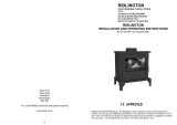
ItemNo Partno Description ItemNo Partno Description
1* 008/FW29 Door Seal Adhesive
37 010/KZ044 Slider Air Control Backing Plate
2 006/KZ018 Glass Inc. Seal
38 004/KZ043 Wood/Multifuel Surround Plate
2a 008/KZ024 Glass Seal
39 004/KZ045 Slider Wood/Multifuel
3 008/KZ074 Door Rope
40 004/EZ014 Wood/Multifuel Selection Lever
4 004/EZ023 Glass Retainer
41 008/KZ006 Airbox Gasket
5 011/KZ029S Fire Brick Set (4)
42 008/KZ047 Slider Control Gasket
6 011/KZ031 Brick Throat Plate
43 010/KZ005 Air Slider Control Plate
7 010/KZ032 Upper Baffle Plate
44 004/KZ020 Air Control Slider
8 010/ER036 Brick Retaining Washer
45 004/BR015 Clicker Retainer Plate
9 008/FFB125 Coach Bolt M6 x 45
46 008/ES36/01 Brass Ball Catch
10 004/XV30 Brick Bracket
47 004/EZ016 Control Rod
11 010/KZ083 Mover Bar
48 012/EZ105 Air Control Handle
12 002/CG01S6 Set of Grate Bars (6)
49 008/BR052 Felt Washer
13 010/EZ013 Undergrate Ash Deflector
50 004/CR064 Blanking Plate
14 010/KZ080 Rear Fire Plate
51 008/CR063 Gasket Blanking Plate
15 010/KZ079 Side Fire Plate
52 004/KZ040 Air Box Cover
16 002/SY30 LH Carrier Bar
53 008/FFS062 Defra Stop
17 002/KZ077 RH Carrier Bar
54 004/CR048 Air Inlet Spigot
18 012/FW14 Idler Rod
55 002/KZ065 Door Hinge Bracket
19 002/EZ098 Riddler Knob
56 004/KZ066 Door Hinge Shim
20 002/KZ007 Front Fence
57 008/FFW024 M8 Brass Washer
21 004/KZ017 Ashpan Assembly
58# 001/KZ010 Firebox
22 004/KZ131 Flue Pipe Surround Ring
59 012/KZ011 Serial Label
23 002/KZ009 Cast Top
60# 004/KZ093L Left Side Panel
24 010/KZ132 Blanking Plate
61# 004/KZ093R Right Side Panel
25 008/KZ134 Self Adhesive Webbing
62 010/KZ099 Stand Baseplate
26 010/KZ133 Blanking Plate Retainer
63# 002/KZ071 Store Stand Casting
27 010/AY51 Clamping Plate
64 004/KZ078 Stand Backplate
28 010/EZ012 Top Retaining Bracket
65# 004/KZ102 Lower Heatshield
29 002/KZ003 Door Back Plate
66# 004/KZ103 Upper Heatshield
30 002/KZ001/A Door Casting
67 004/EZ095 Riddler/ Ashpan Operation Tool
31 010/EZ061 Upper Latch Receiver Plate
68# 010/TW33 Vertical Rear Flue Adapter (Optional Extra)
32# 010/KZ058 Rod Handle Assembly
69# 002/CH12B Flue Collar
33 008/EZ106 Door Handle
70 010/KZ098 Drawer Stand Base Plate (Optional Extra)
34 010/KZ064 Lower Latch Reciever Plate
71# 010/KZ120 Drawer (Optional Extra)
35 002/KZ053 Lower Hinge Bracket
72 004/KZ129 Drawer Runner Support (Optional Extra)
36 002/KZ054 Upper Hinge Bracket
73# 002/KZ135 Drawer Front (Optional Extra)
74# 010/EW51 Ash Carrier (Optional Extra)
* These items are not shown on the drawing
# Please specify colour when ordering.
To obtain spare parts please contact your local stockist
giving Model, Part No. and Description. In case of
difficulty contact the manufacturer at the address
shown.
This drawing is for identification purposes only.
19
24
22
23
28
25
26
27
59
68
69
66
60
65
64
57
55
56
61
53
54
52
51 50
49
7
6
10
5
5 9 8
5
13
14
15
18
11
19
16
17
20
63
3 29 4 2a 36 30
3233
35
71
72
73
70
21
62
37
38
39
4843
41
46
45
42
44
40
47
2
12
31
34
58
67

Issue B
®
CHARNWOOD ARC 7 LOW PARTS LIST
Item Part No. Description Item Part No. Description
1* 008/FW29 Door Seal Adhesive
34 010/KZ064 Lower Latch Reciever Plate
2 006/KZ018 Glass Inc. Seal
35 002/KZ053 Lower Hinge Bracket
2a 008/KZ024 Glass Seal
36 002/KZ054 Upper Hinge Bracket
3 008/KZ074 Door Rope
37 010/KZ044 Slider Air Control Backing Plate
4 004/EZ023 Glass Retainer
38 004/KZ043 Wood/Multifuel Surround Plate
5 011/KZ029S Fire Brick Set (4)
39 004/KZ045 Slider Wood/Multifuel
6 011/KZ031 Brick Throat Plate
40 004/EZ014 Wood/Multifuel Selection Lever
7 010/KZ032 Upper Baffle Plate
41 008/KZ006 Airbox Gasket
8 010/ER036 Brick Retaining Washer
42 008/KZ047 Slider Control Gasket
9 008/FFB125 Coach Bolt M6 x 45
43 010/KZ005 Air Slider Control Plate
10 004/XV30 Brick Bracket
44 004/KZ020 Air Control Slider
11 010/KZ083 Mover Bar
45 004/BR015 Clicker Retainer Plate
12 002/CG01S6 Set of Grate Bars (6)
46 008/ES36/01 Brass Ball Catch
13 010/EZ013 Undergrate Ash Deflector
47 004/EZ016 Control Rod
14 010/KZ080 Rear Fire Plate
48 012/EZ105 Air Control Handle
15 010/KZ079 Side Fire Plate
49 008/BR052 Felt Washer
16 002/SY30 LH Carrier Bar
50 004/CR064 Blanking Plate
17 002/KZ077 RH Carrier Bar
51 008/CR063 Gasket Blanking Plate
18 012/FW14 Idler Rod
52 004/KZ040 Air Box Cover
19 002/EZ098 Riddler Knob
53 008/FFS062 Defra Stop
20 002/KZ007 Front Fence
54 004/CR048 Air Inlet Spigot
21 004/KZ017 Ashpan Assembly
55 002/KZ065 Door Hinge Bracket
22 004/KZ131 Flue Pipe Surround Ring
56 004/KZ066 Door Hinge Shim
23 002/KZ009 Cast Top
57 008/FFW024 M8 Brass Washer
24 010/KZ132 Blanking Plate
58# 001/KZL010 Firebox
25 008/KZ134 Self adhesive webbing
59 012/KZL011 Serial Label
26 010/KZ133 Blanking Plate retainer
60# 004/KZL093L Left Side Panel
27 010/AY51 Clamping plate
61# 004/KZL093R Right Side Panel
28 010/EZ012 Top Retaining Bracket
62# 002/KZL090 Front Casting
29 002/KZ003 Door Back Plate
63# 004/KZ103 Heatshield
30# 002/KZ001/A Door Casting
64 004/EZ095 Riddler/ Ashpan Operation Tool
31 010/EZ061 Upper Latch Receiver Plate
65# 010/TW33 Vertical Rear Flue Adapter (Optional Extra)
32# 010/KZ058 Rod Handle Assembly
66# 002/CH12B Flue Collar
33 008/EZ106 Door Handle
67 010/EW51 Ash Carrier (Optional Extra)
* These items are not shown on the drawing
# Please specify colour when ordering.
To obtain spare parts please contact your local stockist
giving Model, Part No. and Description. In case of
difficulty contact the manufacturer at the address
shown.
This drawing is for identification purposes only.
20
65
63
60
23 61 13 14
50
51
53
54
58
10
18
15 16
11
17 20
19
64 5
6
7
5 9 8
62 3 29 4
2
2a
30 31
3435
5657
12
37
38
39
43
41
46
45
4852 49
47
40
28
42
44
36
27
22
24
55
66
33
32
59
25
26
21
Page is loading ...
Page is loading ...
Page is loading ...
Page is loading ...
-
 1
1
-
 2
2
-
 3
3
-
 4
4
-
 5
5
-
 6
6
-
 7
7
-
 8
8
-
 9
9
-
 10
10
-
 11
11
-
 12
12
-
 13
13
-
 14
14
-
 15
15
-
 16
16
-
 17
17
-
 18
18
-
 19
19
-
 20
20
-
 21
21
-
 22
22
-
 23
23
-
 24
24


Charnwood Arc 5 Operating instructions
- Category
- Fireplaces
- Type
- Operating instructions
- This manual is also suitable for
Ask a question and I''ll find the answer in the document
Finding information in a document is now easier with AI
Related papers
-
Charnwood Country 4 Operating instructions
-
-
-
-
-
-
-
-
-
Other documents
-
River of Goods 19701 Installation guide
-
 Valor Fires Ridlington Installation And Operating Instructions Manual
-
 Hunter Stoves Herald 6 CE VII Installation And Operating Instructions Manual
-
Esse 100 MF SE Installation & User's Instructions
-
-
 Acquisitions Bloomsbury SE Installation & User's Instructions
-
 Hunter Stoves HERALD 5 SLIMLINE CE VII Installation And Operating Instructions Manual
-
-
-
 Broseley Evolution 5 Multifuel Stove Installation guide


