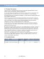
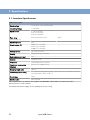
Westermo Lynx 5612-E-F4G-T8G-LV is a high-performance industrial Gigabit switch designed for demanding applications in harsh environments. With its robust design, wide operating temperature range (-40 to 75°C), and comprehensive security features, it is ideal for use in industrial automation, transportation, and energy distribution systems. It features 12 Gigabit Ethernet ports, 4 SFP/SFP+ ports, and 8 Gigabit SFP/SFP+ ports, providing flexible connectivity options for various network topologies.
Westermo Lynx 5612-E-F4G-T8G-LV is a high-performance industrial Gigabit switch designed for demanding applications in harsh environments. With its robust design, wide operating temperature range (-40 to 75°C), and comprehensive security features, it is ideal for use in industrial automation, transportation, and energy distribution systems. It features 12 Gigabit Ethernet ports, 4 SFP/SFP+ ports, and 8 Gigabit SFP/SFP+ ports, providing flexible connectivity options for various network topologies.


-
 1
1
-
 2
2
-
 3
3
-
 4
4
-
 5
5
-
 6
6
-
 7
7
-
 8
8
-
 9
9
-
 10
10
-
 11
11
-
 12
12
-
 13
13
-
 14
14
-
 15
15
-
 16
16
-
 17
17
-
 18
18
-
 19
19
-
 20
20
-
 21
21
-
 22
22
-
 23
23
-
 24
24
-
 25
25
-
 26
26
-
 27
27
-
 28
28
-
 29
29
-
 30
30
-
 31
31
-
 32
32


Westermo Lynx 5612-E-F4G-T8G-LV User guide
- Type
- User guide
- This manual is also suitable for
Westermo Lynx 5612-E-F4G-T8G-LV is a high-performance industrial Gigabit switch designed for demanding applications in harsh environments. With its robust design, wide operating temperature range (-40 to 75°C), and comprehensive security features, it is ideal for use in industrial automation, transportation, and energy distribution systems. It features 12 Gigabit Ethernet ports, 4 SFP/SFP+ ports, and 8 Gigabit SFP/SFP+ ports, providing flexible connectivity options for various network topologies.
Ask a question and I''ll find the answer in the document
Finding information in a document is now easier with AI
Related papers
-
Westermo RFI-219-F4G-T7G-F8-EX User guide
-
Westermo Lynx 5512-F4G-T8G-LV User guide
-
-
Westermo Lynx 5612-F4G-T8G-LV User guide
-
Westermo Lynx 5512 User guide
-
-
Westermo L208-F2G-S2 User guide
-
Westermo L106-F2G User guide
-
-
Other documents
-
Victron energy Lynx Power In Owner's manual
-
Intelligent Motion Systems Modular LYNX System User manual
-
Cooler Master C-2021-W1 Datasheet
-
-
ABB NE840 User manual
-
-
-
-
-