Page is loading ...

www.acclaimlighting.com
Cylinder One HO
User guide


1
www.acclaimlighting.com
CONTENTS
INTRODUCTION ......................................................2
Welcome 2
Safety 2
Maintenance 2
Cleaning 2
Supplied items 3
Accessories 3
INSTALLATION ......................................................... 4
Mounting 4
Junction box connections 9
Reflectors 10
Trim rings 11
Power and control wiring 12
Wireless control 14
OPERATION ........................................................... 16
Making a temporary control link with the XMT-350 16
Addressing fixtures 17
Configuring the Aria wireless DMX receiver 18
Testing emitter output 19
FURTHER INFORMATION ...................................... 20
Troubleshooting 20
Optimizing signal strength via channel selection 21
Specifications 22
Dimensions 23
Limited product warranty 26

2
www.acclaimlighting.com
INTRODUCTION
WELCOME
Welcome to the Cylinder One range from Acclaim Lighting.
These aluminum bodied fixtures provide high output long throw
downlighting for interior spaces.
The Cylinder One range fully embraces Acclaim Lighting’s
Modular Systems (AMS) design standard; AMS allows a
wider choice of options to be configured in our Los Angeles
headquarters and delivered within industry-leading timescales.
Cylinder One fixtures provide four distinct mounting options; four
different emitter choices with varying color temperatures and
also varying beam widths delivered by quick change reflectors:
• Surface, pendant, aircraft cable or wall mounting,
• 2700K, 3000K, 3500K or 4000K high-CRI color temperatures,
• 15º, 22º 40º or 70º beam widths via quick change reflectors.
Control is achieved using the industry standard DMX with RDM
support for addressing and configuration. Each Cylinder One
fisture is supplied with 20’ (6m) power and control cords.
Aria™ wireless DMX control is fitted as standard to every Cylinder
One fixture, promoting rapid deployment without the need to
retrofit control cabling to existing structures.
The internal auto-sensing power supply within each unit can
accept mains inputs between 100 to 277VAC at 50 or 60Hz. Total
power consumption is just 135W at full output.
SAFETY
• When fixtures are mounted off-ground, ensure they are securely fitted to an appropriate
mounting surface.
• Ensure that the power input is supplied from a correctly fused, earthed and
environmentally protected location.
MAINTENANCE
CAUTION: Always isolate mains power before starting maintenance operations.
• Ensure that all mounting (and device) screws/bolts are fully tight and free of corrosion.
• Ensure there is no deformation to the housing, lenses or fixing points.
• Check that all power supply cables are free from physical damage or material fatigue.
• Use only genuine spare parts supplied by Acclaim Lighting.
CLEANING
• Use a moist, lint-free cloth when cleaning each fixture.
• Never use alcohol or solvents.

3
www.acclaimlighting.com
SUPPLIED ITEMS
ACCESSORIES
Cylinder One
With chosen mount type (A, B, C or D),
reflector and 20’ (6m) power and
control tails.
Vaulted ceiling mount
[COHVCM]
NPS pipe
(3/4” NPS, O/D=1.050”)
12” gray [NPS34-12G]
24” gray [NPS34-24G]
36” gray [NPS34-36G]
(For other colors,
substitute G sux for:
B = black
W = white
C = custom)
Illuminated
trim ring
[COHTR]
A pendant mount is
supplied as standard
with the 3/4” NPS
mounting option.

4
www.acclaimlighting.com
Mounting holes
3 x Ø0.26” (6.5mm)
with Ø0.51” (13mm)
countersink
Top plate
with 3
locking
lugs
Safety wire
Attach to
a suitable
anchor point
Slots for
locking
lugs (x3)
INSTALLATION
MOUNTING
Four different (factory fitted) mounting options are available for Cylinder One fixtures.
Note: Please see the junction box details given on page 9.
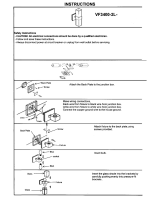
SURFACE MOUNT [TYPE A]
This mount allows the top surface of the Cylinder One fixture to be fixed almost flush to the
ceiling above. A locking top plate allows quick mounting and dismounting of the fixture.
• To disconnect the xture body from the top plate: Push the fixture body up against
the top plate then twist
the body clockwise (as
viewed from the emitter
end) to release.
• Use three countersunk
screws/bolts that are
load rated (Grade 5
or greater fixings are
strongly recommended)
and suitable for the
mounting surface.
• Ensure that there’s a
suitable solid mounting
surface for the three
countersunk mounting
screws/bolts to connect
with.
• Ensure that the safety
wire is attached
to a suitable
anchor point
within the ceiling
space.
• To reconnect
the xture
body to the top
plate: Ensure
the locking lugs
of the top plate
engage with the
three holes in the
upper surface of
the main body.
Push the fixture
body up against
the top plate
then twist the
body counter-clockwise (as viewed from the emitter end) to lock into place. Ensure that
the lugs are fully locked and the fixture body cannot fall.

5
www.acclaimlighting.com
3/4” NPS PENDANT MOUNT [TYPE B]
This mount allows the Cylinder One fixture to be mounted as a pendant light, with a choice
of three pipe sizes (from 12” to 36”) connecting to either a fixed or a swivel bracket (for
vaulted ceilings).
• Feed the power and signal cables, plus the safety wire through the chosen pipe and
carefully screw it all the way into the threaded cup on the top surface of the Cylinder One
fixture - take great care not to snag the cables within the pipe as it is rotated into place.
• Ensure that the two grub screws in the threaded cup are fully tightened to prevent any
movement of the pipe - requires a 2mm Allen wrench (not supplied).
• Attach the required bracket to the other end of the pipe - see page 6.
• Note: Please see the junction box details given on page 9.
Use 2mm Allen wrench (not
supplied) to tighten grub screws
(x2) to prevent pipe movement
Screw in chosen pipe size into the
threaded cup - take care not to
snag cables as the pipe is rotated
For dimensions, please see pages 23 to 25.

6
www.acclaimlighting.com
2mm Allen
wrench (not
supplied)
3/4” NPS PENDANT MOUNT - BRACKETS [TYPE B]
Two types of bracket are available for use with the 3/4” NPS pendant version of the Cylinder
One - a fixed vertical type for level surfaces or a swivel type for vaulted ceilings. The swivel
type can be angled up to 60
O
from vertical.
• Fit the chosen pipe to the Cylinder One fixture as outlined on page 5.
• Feed the power and signal cables, plus the safety wire from the pipe through the threaded
cup of the bracket - take great care not to snag the cables as it is rotated into place.
• Ensure that the two grub screws in the threaded cup of the bracket are fully tightened to
prevent any pipe movement - requires either a 2mm or 2.5mm Allen wrench (not supplied).
• Remove the two screws that hold the cover plate in place to gain access to the mount holes.
• Use two screws/bolts that are load rated (Grade 5 or greater fixings are strongly
recommended) and suitable for the surface to fix the bracket.
• Ensure that there’s a suitable solid mounting surface for the two mounting screws/bolts
to connect with.
• Ensure that the safety wire is attached to a suitable anchor point within the ceiling space.
2.5mm Allen
wrench (not
supplied)
Use 5mm Allen
wrench (not
supplied) to adjust
angle
Cover plate
For dimensions, please see pages 23 to 25.
• Note: Please see the junction box
details given on page 9.

7
www.acclaimlighting.com
AIRCRAFT CABLE MOUNT [TYPE C]
This mount allows the Cylinder One fixture to be hung from a securely mounted hook or
ring.
• Ensure that the chosen hook is sufficiently load rated (Grade 5 or greater fixings are
strongly recommended) for the weight of the fixture and is securely attached to the
mounting surface.
• Note: Please see the junction box details given on page 9.
For dimensions, please see pages 23 to 25.

8
www.acclaimlighting.com
WALL MOUNT [TYPE D]
This mount allows the Cylinder One fixture to be secured directly to a vertical wall surface.
• Ensure that the wall surface is of sound construction and able to support the weight of
the fixture.
• Use load rated fixings (Grade 5 or greater fixings are strongly recommended) that are
appropriate to the wall construction.
• Ensure that the safety wire is attached to a suitable anchor point within the wall space.
• Note: Please see the junction box details given on page 9.
For dimensions, please see pages 23 to 25.

9
www.acclaimlighting.com
JUNCTION BOX CONNECTIONS
In-line with best practice, you are recommended to install a suitable junction box above or
close to each Cylinder One fixture. Please note the following:
• The mains power supply and the DMX control signals must be contained within
separated compartments, or alternatively within different junction boxes.
• Ensure that the junction box dimensions and its positioning does not interfere with the
mounting structure for the Cylinder One fixture itself.
• For power and control wiring information, see page 12.
Power and control
feed down to
xture
Power and DMX
control inputs
Third party junction
box suitable for the
mounting surface

10
www.acclaimlighting.com
REFLECTORS
A selection of reflectors are available to allow you to match the correct beam size to each
installation space. Reflectors are quick and easy to change.
Note: Take care not to disturb the Aria antenna which is adjacent to the locking tab ring.
TO REMOVE A REFLECTOR
1 Gently push the reflector
in towards the fixture.
2 Twist the reflector
counter-clockwise as
far as it will go until it
disengages.
3 Remove the reflector.
TO FIT A REFLECTOR
1 Align the three cut outs in the base of the reflector with the three locking tabs located on
the ring that surrounds the LED emitter.
2 Gently push the reflector onto the locking tabs and twist it clockwise until it locks into
place.
Reector
locking
tab ring
Aria
antenna

11
www.acclaimlighting.com
TRIM RINGS
The standard trim ring (which surrounds the reflector) can be replaced for an optional
model with an illuminating edge.
Note: Take care not to disturb the Aria antenna which is adjacent to the locking tab ring.
TO CHANGE THE TRIM RING
1 Remove the
reflector as
discussed on
page 10.
2 Remove the six
screws which
secure the trim
ring.
3 Fit the new trim
ring, align the six
mounting holes
and replace the
screws to secure
it.
4 Replace the
reflector as
discussed on
page 10.
Aria
antenna

12
www.acclaimlighting.com
POWER AND CONTROL WIRING
The power and control cords (each roughly twenty feet, 6m in length) are supplied with
bare tails.
POWER CONNECTIONS
The power requirements are as follows:
• Voltage: 100-277VAC 50/60Hz
• Power: 135W steady state
The power cord color designations are as follows:
IN-RUSH CURRENT
Although LED fixtures are low power devices compared to their incandescent equivalents,
their power supplies exhibit a trait known as ‘in-rush current’ when they are first powered
on. This is caused by the various components within the switching power supplies topping
themselves up with power. The in-rush current period lasts only milliseconds and does not
cause any effect when a handful of units are powered on at the exact same time. However,
if many fixtures are linked to the same power input, they will momentarily pull a current that
may greatly exceed their normal operating level. This may affect over-current trips when
power is applied. For this reason it is advisable to limit the number of fixtures on any one
power input.
White: Neutral
Black: Live
Green: Earth
Red/White: DMX + (Hot)
Black: DMX - (Cold)
< DMX IN
> DMX OUT
Black/White: DMX - (Cold)
Red: DMX + (Hot)
Green: Ground
CONTROL CONNECTIONS
The DMX control cord color designations are as follows:
Ensure that the power input is supplied from a correctly fused, earthed and environmentally
protected location.

13
www.acclaimlighting.com
CONTROL CONNECTIONS FOR MULTIPLE FIXTURES
When connecting multiple fixtures, connect the DMX control input lines to the first fixture
and feed the output of that fixture to the next. The final fixture in the line should have a
120Ω terminating resistor connected between the DMX + and DMX – lines:
TIPS FOR ACHIEVING SUCCESSFUL DMX CONTROL
• Do not exceed a total cable length of 3,900 ft (1200m) without buffering.
• Do not exceed a total of 32 fixtures on a single line without buffering.
• Use only connection cables with a characteristic impedance of 120Ω, preferably where
the DMX + and DMX – data lines are twisted around each other and the ground link exists
as a coaxial screen surrounding the inner cores.
• Connect a 120Ω terminating resistor between the DMX + and DMX – output connections
of the final fixture.
• Do not introduce a passive Y-split into the control cabling. If it is necessary to split the
control link in order feed fixtures located in different directions, use a powered DMX
splitter/buffer.
• Ensure that the DMX + and DMX – connections do not become crossed at any point.
Red
Red
Red
DMX +
DMX –
Ground
Black
Black
Black
Green
Green
Green
Black/White
Black/White
Black/White
Red/White
Red/White
Red/White
120Ω
Cylinder One HO
1
Cylinder One HO
2
Cylinder One HO
32

14
www.acclaimlighting.com
WIRELESS CONTROL
The embedded Aria™ wireless system allows you to control any number of Cylinder One
fixtures that are within range of an Aria transmitter set to use the same wireless address
(channel):
Notes:
The wireless address (channel) is totally
independent of the DMX address.
To aid clarity, the necessary power
cables for each fixture are not shown in
these diagrams.
Optional Aria
transmitter
Wireless Chan: 2
DMX Addr: 100
Wireless Chan: 2
DMX Addr: 101
Wireless Chan: 2
DMX Addr: 102
DMX IN
Tx
To configure the wireless feature, an RDM set up tool is
required. Although many models work, Acclaim Lighting
recommends an XMT 350 when enabling the wireless
function and setting the appropriate channel. See page
18 for details.
MODE
100%
50%
CH
CH
0
(toggle)(func)
ALWAYS CARRY OUT A SPECTRUM ANALYSIS
Prior to using the Aria™ wireless feature, Acclaim Lighting recommends that you perform
a spectrum analysis of the on site radio frequencies to ensure the system will function
correctly at the planned location.
Please also see page 21 for details about channel selection.

15
www.acclaimlighting.com
Wireless Chan: 2
DMX Addr: 100
DMX Addr: 101
Non-Aria equipped fixtures (e.g. Pixel Graze)
DMX Addr: 105
DMX IN
Tx
See “Configuring the Aria wireless DMX
receiver” on page 18 for details about
configuring the wireless address.
USING A CYLINDER ONE AS A WIRELESS HUB
When a Cylinder One fixture receives a wireless input (and it has no wired DMX input), it will
automatically output the full received DMX universe on its output wires. This means that you
can wire through and control up to 32 non-Aria DMX fixtures (such as Pixel Graze), or more,
if an active repeater is used.

16
www.acclaimlighting.com
OPERATION
Cylinder One fixtures have no external controls and instead rely on RDM (Remote Device
Management) for all configuration via the DMX interface. This allows multiple devices to be
configured either before or after installation (when fully cabled).
The main items that can be configured on each fixture (via RDM) are:
• DMX address (see page 17)
• Aria™ wireless receiver (see page 18)
Various third party DMX/RDM tools are available; we recommend the Acclaim Lighting XMT-
350 for this task.
MAKING A TEMPORARY CONTROL LINK WITH THE XMT-350
Each Acclaim lighting XMT-350 DMX/RDM tool is supplied with a 5-pin male XLR lead that
can be used to make a temporary control input link with the Cylinder One feed-in cable. Use
a 3-pin terminal block, wire nuts, conn blocks or Wago® connectors to temporarily join the
two cables:
Cylinder One
feed-in
cable
Male XLR
lead from
XMT-350
Black
Gray
Red
Red
Green
Black
DMX + (Hot)
DMX–(Cold)
Ground
Note: It is not possible to carry out RDM configuration on fixtures via the Aria wireless DMX link.

17
www.acclaimlighting.com
ADDRESSING FIXTURES
TO ADDRESS FIXTURES USING THE ACCLAIM LIGHTING XMT-350
1 Connect the XMT-350 to the DMX input line of either a single fixture or multiple fixtures in
a pre-arranged daisy chain configuration (see page 13).
2 Power on the fixture(s) and the XMT-350.
3 On the XMT-350, press the MODE button, then use the arrow buttons to highlight the RDM
function and press the
button to select. The XMT-350 will search for RDM devices and
after a short while the XMT-350 will display a list of all located fixtures:
ACTUAL ADDRESS:
PATCH TO ADDRESS:
OK CANCEL
001
001
CYLINDER ONE HO
(001)
MAIN
CYLINDER ONE HO
CYLINDER ONE HO
CYLINDER ONE HO
002
003
004
PATCH OPTIONS 004/004
RESTARTPATCHING
MAIN
CYLINDER ONE HO
CYLINDER ONE HO
CYLINDER ONE HO
002
003
004
PATCH OPTIONS
004/004
CYLINDER ONE HO
001
The fixture that is highlighted within the list should begin flashing its emitters to identify
itself.
4 On the XMT-350, press the right arrow button to change to the PATCH tab:
5 If necessary, use the up/down buttons to choose an alternative fixture.
6 Press the
button to set the address for the currently highlighted fixture:
7 Use the up/down buttons to set the required DMX address and then press the
button
to store it within the fixture.
8 The highlight will automatically move to the next fixture so that you can address it.
Repeat steps 5 to 7 until all fixtures are addressed.
Note: DMX addresses shown in brackets, e.g.
(001), have been temporarily assigned by the
XMT-350, but are not yet stored within the
fixture(s).

18
www.acclaimlighting.com
CONFIGURING THE ARIA WIRELESS DMX RECEIVER
Each Cylinder One fixture includes an internal Aria™ wireless DMX
receiver unit to allow it to be remotely controlled by an Acclaim
Lighting Aria transmitter. Fifteen radio addresses (channels)
are available to choose from, allowing you to avoid potential
interference sources, such as WiFi access points, and set up parallel
wireless links between different sets of Aria units. Cylinder One
fixtures are shipped with the wireless system enabled (this does not prevent direct control
via the cable) and the wireless address (channel) set to 0 as standard. For more details about
choosing the most suitable wireless address (channel), see page 21.
Using an RDM (Remote Device Management) tool, you can quickly change between the
various DMX personality modes. Various third party DMX/RDM tools are available; we
recommend the Acclaim Lighting XMT-350 for this task.
TO CONFIGURE WIRELESS DMX USING THE ACCLAIM LIGHTING XMT-350
1 Connect the XMT-350 to the DMX input line of either a single fixture or multiple fixtures in
a pre-arranged daisy chain configuration.
2 Power on the fixture(s) and the XMT-350.
3 On the XMT-350, press the MODE button, then use the arrow buttons to highlight the
RDM function and press the
button to select. The XMT-350 will search for RDM devices
and after a short while the XMT-350 will display a list of all located fixtures. The fixture that
is highlighted within the list should begin flashing its emitters to identify itself.
4 If necessary, use the up/down buttons to highlight an alternative fixture.
5 Press the
button to view details for the chosen fixture and then use the down button
to highlight the MODEL entry:
6 Press the
button to view the options:
Within this menu, you can change the wireless address (channel) and also enable/disable
the wireless receiver circuit.
7 To change the wireless address (channel): Use the up/down buttons to highlight the
WIRELESS ADDR option and press the
button. Use the up/down buttons to select the
required address (between 0 and 14) and press the
button. For more details about
choosing the most suitable radio address, see page 21.
8 Press the button to return to the previous screen.
CYLINDER ONE HO
MODEL: CYLINDER ONE HO
MAN:
DMX START ADDRESS:
DMX SLOTS:
ACCLAIM
001
1
LABEL: CYLINDER ONE HO
DMX PERSONALITY:MODE1: 1-SL...
CYLINDER ONE HO
0
WIRELESS ON/OFF ON
WIRELESS ADDR
/