KitchenAid GBD307PDB7 Installation guide

Category
Ovens
Type
Installation guide
\
Quick Reference
Tabmeof Contents:
Pages
1_ Product dimensions
[_ Cutout dimensions
Before you start
j_ Electrical requiremer_ts
[_ [_ Inst_llationsteps
If you need assistance:
Check your Use and Care Guide for a toJJ-freenumber to caJJor call
the deaUerfrom whom you purchased this appliance. The dealer is
listed in the Yellow Pages of your phone directory under
"AppJiances -- Household -- Major -- Service and Repair."
Call when you:
_1 Have questions about built-in even installation or operation.
{_ Need to obtain the name and number of an authorized service
company.
When you caUl,you will need:
[_ The buik-in oven model number.
The builtqn oven serial number.
Both numbers are listed on the model/serial rating plate, located on
the oven door or on the oven frame.
SingUe oven
28o3/8" raax.
recessed
width
27-1/2"
recessed
height
27=3/4"
rain,
cutout
height
27=3/4"
rain,
cutout
height
1=1!2"
rain,
bottom of
cutout to
top of
cabinet
door
30" rain, --_
cabinet width
Single oven
undercounter
(without cooktop
installed above}
uu - ,
cb e dtb
28-I/2"
_-- cutout ---}_
width
Single oven
Page 1
29" max,
overati
height
OoubUe oven
2S"raa×,
recessed
depth
49=1/2"
recessed
height
29=3/4"
5I" raa×=
overall
height
r
J
1=1/2" rein.
top of cutout
to underside
of countertop
49=3/4"
rain=
cutout
height
5=I/4" bottora of
cutout to floor
1=1/2" pain,
bottom of
cutout to top of
cabinet door
30" rein,
_--- cabinet
28=1/2"
-._--- cutout ---_
width
Doubb oven
1" top of cutout
to bottora of
upper cabinet
door
14=3/4"
bottom
of cutout
to eoor
1" top of cutout
to bottom of
upper cabinet
door
cabinet/-_
23=1/4"rain.
cutout depth
23"recessed
oven depth
recessed
oven
oven
_/'front
t
32"
bottom of
cutout to
floor
Cabinet side view
Cabinet filler kits are available from your dealer.
Use a matching color kit if oven is smaller than your
Single oven filler height is 3-5/18"
Black -- 4378941
White -- 4378942
Almond- 4378943
Doubb oven filler height is 6-5/16"
Black -- 4378947
White -- 4378948
Almond- 4378949
Your safety ned the safety of others are
very important,
We haveprovided many important safety
messagesin this manualand on your appliance.
Atways read and obeyaIIsafety messages.
This is the safety alertsymbol.
Thissymboi alertsyou to potential hazards
that cankiii or hurtyou and others.
Ati safety'messageswiii foiiow the safetyalert
symbol andeitherthe word "DANGER"or
"WARNING".Thesewords mean:
Yea can be killed or seri0asty injured ifyou
don't f0H0w instructions.
AIi safety messageswiii teii you what the potential
hazardis, tell you howto reducethe chance of
injury, andteti you what can happenif the
instructions are not followed.
important: Observe all governing codes
and ordinances.
Proper installation isyour responsibility.
Have a qualified technician install this oven.
Oven bcation should be away from strong draft
areas, such as windows, doors and strong
heating vents.
Cabinet opening dimensions that are shown
must be used. Given dimensions provide
minimum clearance.
Recessed installation area must provide
complete enclosure around the recessed portion
of the oven.
Ebctrical ground is required. See "Electrical
requirements."
Ebctrical supply junction box should be located
3 inches maximum below the support surface
when oven is installed in a wall cabinet. Drill a
14nch minimum diameter hob in the right rear
or [eft rear corner of the support surface to pass
the appliance came through to the junction box.
For undercounter installation, it is recommended
that the junction box be located in the adjacent
right or left cabinet, if installing the junction box
on rear wall behind oven, junction box must be
recessed and located in the upper or lower right
or left corner of cabinet.
Oven support surface MUST be solid, level and
flush with bottom of cabinet cutout.
It is the customer's responsibility:
To contact a qualified electrical installer.
To assure that the electrical installation is
adequate and in conformance with National
Electrical Code, ANaltNFPA 70 _ latest edition*,
and nit local codes and ordinances.
Copies of the standards _isted may be obtained from:
* National Fire Protection Association
Batteryraarah Park
Quincy, Massachusetts 02289
Tool needed:
Phillips
screwdriver
Partssupplied:
(_ 4 screws (double oven)
If codes permit and a separate grounding wire is
used, it is recommended that a qualified electrician
determine that the grounding path and wire gauge
is in accordance with local codes.
Do Not ground to a gas pipe.
Check with a qualified electrician if you are not
sure oven is proper_y grounded.
Do Not have a fuse in the neutraJ or grounding
circuit.
Oven must be connected to the proper eUectricaU
voUtageand frequency as specified on the
modeU/sedaUrating pUate.(The modeU/sedaUrating
plate is located on the oven door or on the oven
frame.)
[_ Models rated from 7.3to 9.6 kW at 240 volts
(5.5to 7.2 kW at 208 volts} require a separate
@-ampere circuit. Models rated at 7.2 kW and
below at 240 volts (5.4 kW and below at 208
volts} require a separate 30-ampere circuit.
[_ A time-delay fuse or circuit breaker is
recommended.
[_ Connect directly to the fused disconnect (or
circuit breaker box} through flexible, armored
or non-metallic sheathed, copper cable (with
grounding wire}.
[_ Flexible armored cable from appliance should
be connected directly to junction box.
[_ Fuse both sides of the line.
[_ A U.L.qisted conduit connector must be
provided atthe junction box.
[_ Do Not cut the conduit.
Wire sizes and connections must conform with the
rating of the appliance and to the requirements of
the National Electrical Code, ANSI/NFPA 70 -- latest
edition (% See Page 1) and all local codes and
ordinances.
if the house has aluminum wiring, follow the
procedure below.
a.) Connect the aluminum wiring to the copper
wire using special connectors designed and
Underwriters Laboratories-listed for joining
copper to aluminum. Follow the electrical
connector manufacturer's recommended
procedure.
b.) Aluminum/copper connection must conform
with local codes and industry-accepted wiring
practice.
Use screws to attach
oven to cabinet.
Reattach side
pieces.
Remove side
trim.
Remove
trim screws.
_ Grasp oven
frame to lift
oven.
t
Use screws to attach
oven to cabinet.
Reattach side
_eces,
Remove side
trim,
shipping
feet,
Replace
oven door.
Preparation
Excessive Weight Hazard
Use two or more people to move and
install oven.
Failure to follow this instruction can
result in back or other injury.
Important: Use both hands to remove oven
doors.
Do Not use handb or any portion of the front
frame or trim for lifting.
Before moving oven across floor, check that oven
is on shipping base or sJide oven onto cardboard
or hardboard,
Do Not remove shipping feet at the front tower
corners of oven.
Remove
oven door.
Remove trim
screws,
Remove
oven doors.
Replace
oven doors.
{ateh on the hinge
in {ocked position =
door free to open
and close
latch on the hinge
position = door
ready for removal
_" Remove trim screw,
Pull trim out,
'.TurnpowersuppUy
off. Move oven close to
final position.
, Remove and discard
shipping materials, tape
and protective film from DoNot
the oven. Do Not re
remove shipping base shippingfeet,
or shipping feet at the front Jower corners of
oven. The shipping feet will protect the Jower
oven trim unti_ oven is inserted into cabinet.
, Remove and set aside racks and other parts
from inside oven.
m Completely open oven door. In both back
corners of the door you will see door latches in the
locked position. Rotate both latches forward to the
unlocked position.
Grasp outside edges of door with both hands.
, Begin closing door, atthe moment the door
stops closing, lift and puii door toward you.
Set door aside on a protective surface.
Pull top of trim
down,
3R Remove trim screws attaching right and
left side trim to oven. Grasp the bottom end of
trim and pull away from oven. Slide top end of
trim downward to remove trim from oven. Take
care not to scratch other surfaces with ends of
trim. Set trim and screws aside on protected
surface.
Page 2
Electricalconnection
If your house has aluminum w,Mng, see
"Ebctdcal requirements", Page2.
Electrical Shock Hazard
Turn power supply off before connecting wires.
Use 8 gauge solid copper wire.
Ebctricaiiy ground range.
Failure to follow these instructions can result
in death, fire, or electrical shock.
Thisoven is manufactured with white {neutral)
power supply wire and a cabinet=connected bare
grounding wire twisted together.
Feed oven cabb through opening in
the cabinet. Make ebctrica[ connection
following the steps needed for your installation.
1. Disconnect the power supply.
2. Remove the junction box cover.
3. Connect oven cable to junction box through the
U.L.-listed conduit connector.
4. Connect the two black wires together with
twist-on connectors.
5. Connect the two red wires together with
twist-on connectors.
6. Complete electrical connection according to
local codes and ordinances.
came from
junction power suppb/
box _
w'rz_ _
white _ -_
w,re _ L>_../
grounding oven
cable wires --
factory crimped
Figure 1 came from
oven
eoeduit
connector
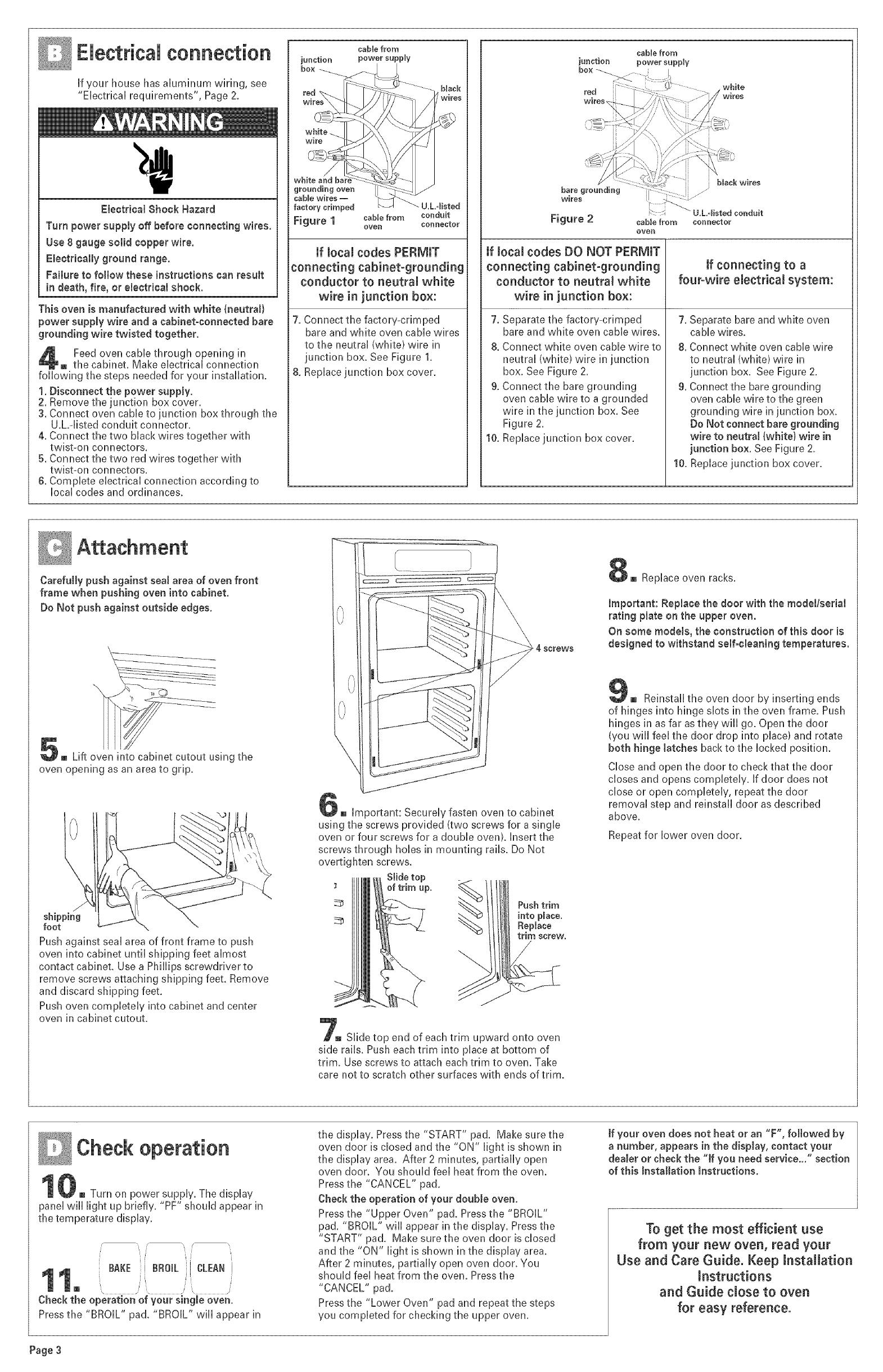
if local codes PERMIT
connecting cabinet-grounding
conductor to neutral white
wire in junction box:
7. Connect the factory-crimped
bare and white oven cable wires
to the neutral (white} wire in
junction box. See Figure 1.
8. Replace junction box cover.
came from
iunction power suppiV
Figure 2
cable from connector
oven
if local codes DO NOT PERMIT
connecting cabinet-grounding
conductor to neutral white
wire in junction box:
7. Separate the factory-crimped
bare and white oven cable wires.
& Connect white oven cable wire to
neutral (white} wire in junction
box. See Figure 2,
9. Connect the bare grounding
oven cable wire to a grounded
wire in the junction box. See
Figure 2.
10. Replace junction box cover,
[f connecting to a
four-wire electrical system:
7. Separate bare and white oven
cable wires.
8. Connect white oven cable wire
to neutral (white} wire in
junction box, See Figure 2.
9. Connect the bare grounding
oven cable wire to the green
grounding wire in junction box.
Do Not connectbare grounding
wire to neutral (white} wire in
junction box. See Figure 2.
10. Replace junction box cover.
Attachment
Carefully push against sea[ area of oven front
frame when pushing oven into cabinet.
Do Not push against outside edges.
5_ Lift __using the
oven opening as an area to grip,
shipping
foot
Push against seal area of front frame to push
oven into cabinet until shipping feet almost
contact cabinet. Use a Phillips screwdriver to
remove screws attaching shipping feet. Remove
and discard shipping feet.
Push oven completely into cabinet and center
oven in cabinet cutout.
4- screws
6u important: Securely fasten oven to cabinet
using the screws provided (two screws for a single
oven or four screws for a double oven}, Insert the
screws through hobs in mounting rails, Do Not
overtighten screws.
Slide top
; oftrim uF _._!
_._-_ Pushtrim
into place.
Replace
trim screw,
/
7m Slide top end of each trim upward onto oven
side rails. Push each trim into place at bottom of
trim. Use screws to attach each trim to oven. Take
care not to scratch other surfaces with ends of trim.
8u Replace oven racks.
important: Replace the door with the model/serial
rating plate on the upper oven.
On some models, the construction of this door is
designed to withstand so[foe[caning temperatures.
g m Reinstall the oven door by inserting ends
of hinges into hinge slots in the oven frame, Push
hinges in as far asthey will go. Open the door
(you will feel the door drop into piacet and rotate
both hinge latches back to the locked position.
Close and open the door to check that the door
closes and opens completely. If door does not
dose or open completely, repeat the door
removal step and reinstall door as described
above.
Repeat for lower oven door.
Check operation
Turn on power supply. The display
panel wili light up briefly. "PF" should appear in
the temperature display.
i i
BAKE i BRO& I CLEAN[
i[ /
/ ',
@1 , /
\ S _ , /'
Check the operation of your single oven.
Press the "BROIL" pad. "BROIL" will appear in
the display. Press the "START" pad. Make sure the
oven door is closed and the "ON" light is shown in
the display area. After 2 minutes, partially open
oven door. You should feel heat from the oven.
Press the "CANCEL" pad.
Check the operation of your double oven.
Press the "Upper Oven" pad. Pressthe "BROIL"
pad. "BROIL" wiil appear in the display. Press the
"START" pad. Make sure the oven door is closed
and the "ON" light is shown in the display area.
After 2 minutes, partially open oven door. You
should feel heat from the oven. Pressthe
"CANCEL" pad.
Press the "Lower Oven" pad and repeat the steps
you completed for checking the upper oven.
[f your oven does not heat or an "F", followed by
a number, appears in the display, contact your
dealer or check the "if you need service..." section
of this installation instructions.
To get the most efficient use
from your new oven, read your
Use and Care Guide. Keep [nstammation
[nstructions
and Guide creeseto oven
for easy reference.
Page3
if oven does not operate:
[_ Checkthat circuit breaker is not tdpped or
house fuse blown.
[_ See Use and Care Guide for troubleshooting list.
if you need assistance:
ff you have questions about operating, c_eaningor
maintaining your oven:
D Refer to Use and Care Guide.
[_ Callthe Consumer Assistance Center: Check
your Use and Care Guide for a toll-free
number to call or call the dealer from whom you
purchased this appliance. The dealer is listed in
the Yellow Pages of your phone directory under
"Appliances -- Household -- Major -- Service
and Repair."
If you need service:
Maintain the quality built into your built-in oven by
calling an authorized service company.
To obtain the name and number of an authorized
service company:
[_ Contact the dealer from whom you purchased
your built-in oven; or
[_ Look in the Yellow Pages of your telephone
directory under "Appliances -- Household --
Major -- Service and Repair" for an authorized
service company; or
[_ Call the Consumer Assistance Center. The toll-
free phone number is listed in your Use and
Care Guide.
When you ca[[, you wi[[ need:
[_ The built-in oven model number.
[_ The built-in oven serial number.
Both numbers are listed on the model/serial rating
plate, located on the oven door or on the oven
frame.
Part No. 8300654
¢) 2001 Printed in U.S.A.
  • Page 1 1
  • Page 2 2
  • Page 3 3
  • Page 4 4
  • Page 5 5

KitchenAid GBD307PDB7 Installation guide

Category
Ovens
Type
Installation guide

Ask a question and I''ll find the answer in the document

Finding information in a document is now easier with AI