Page 3
pressure regulator and natural gas
orifice. Using a natural gas orifice with
an L.P. gas supply can result in personal
injury, clothes damage, and/or a fire
hazard. Have a qualified gas
technician install a conversion kit in
dryer before use.
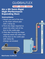
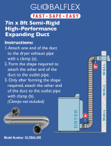
Exhaust requirements
Four Inch Metal Exhaust Duct is re-
quired. (Do not use 3-inch exhaust
duct.) Metal flexible duct may be
used. DO NOT USE PLASTIC
FLEXIBLE DUCT.
For Safety:
• Do not exhaust dryer into a chimney,
furnace cold air duct, attic or crawl
space, or any other duct used for
venting. Accumulated lint could
become a fire hazard or moisture
could cause damage.
• The exhaust system should be
cleaned periodically, at least every
18 months.
• Flexible duct should never be
installed concealed in walls, ceiling
or floor.
Use Duct Tape to seal all joints.
Do not use screws or
bolts which can catch lint and cause
blockage in duct.
Exhausting the dryer outside is
recommended.
A dryer installed in a bedroom, a
bathroom, or a closet MUST be
exhausted to the outside.
No other fuel-burning appliance shall
be installed in the same closet as the
dryer.
For Mobile Home Exhaust
Requirements see Page 7, Alternate
Exhaust Methods, for detailed
instructions.
The Exhaust Duct should end with
an exhaust hood to prevent exhausted
air returning into dryer. The outlet of
the hood must be at least 12 inches
from the ground or anything else that
may be in the path of the exhaust.
A 2-1/2 inch outlet Exhaust Hood
should be used with short systems only.
This outlet creates greater backward
pressure than other hood types.
Exhaust Hoods with screens or
magnetic latches should not be used.
GROUND WIRE
#12 MINIMUM
(NOT SUPPLIED)
GREEN
GROUND
SCREW
Figure 2
Gas requirements
1. Installation must meet American
National Standard, National Fuel
Gas Code ANSI Z 223.1—1988 and
local codes and ordinances.
2. The gas supply line should be 1/2
inch pipe. A 1/2" to 3/8" reducer
must be used to connect the dryer
to the supply line.
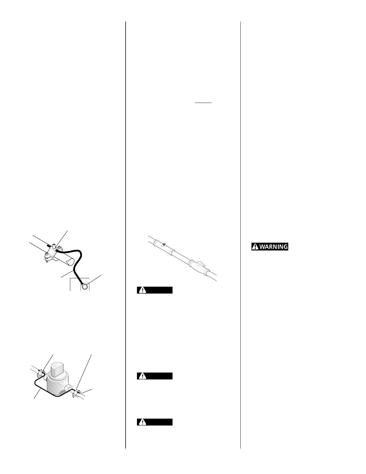
3. The gas supply line
MUST have a
shut-off valve preferably within six
feet of the dryer (Figure 4).
4. A 1/8 inch NPT plugged tapping,
accessible for test gauge
connection, must be installed
immediately upstream of the gas
supply connection. The dryer and
its individual shut-off valve must be
disconnected from the gas supply
piping system during any pressure
testing (Figure 4) of that system at
test pressures in excess 1/2 psig
(3.45 kPa). The dryer must be
isolated from the gas supply piping
system by closing its individual
manual shutoff valve during any
pressure testing of the gas supply
piping system at test pressures equal
to or less than 1/2 psig (3.45 kPa).
DANGER
Do not attempt to alter
gas orifice or adjust burner air shutter.
Natural gas input may vary in some
areas from 700 to 1200 B.T.U. per cubic
foot. If gas orifice or burner air shutter
are incorrectly adjusted, serious
personal injury and/or fire hazard can
occur. Your local gas company will
know the qualities of the gas in your
area. Contact your local servicing
dealer if burner adjustment or orifice
changes are necessary.
DANGER
Do not use an open
flame for leak testing. Serious personal
injury and/or a fire hazard can result if
san open flame is used to test for gas
leaks. Use a soap and water solution
to test all gas line fittings.
DANGER
Do not install dryer to
an L.P. gas supply without installing
conversion kit. All dryers shipped out
of the factory are equipped with a
Figure 4
GROUND CLAMP
(ATTACH TO METAL
COLD WATER PIPE)
Figure 3
NO. 4 WIRE
METAL
WATER
PIPE
GROUND BONDING CLAMP
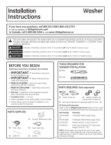
1. A 120 volt, 60 Hz, AC only electrical
supply is required on a separate 15
ampere circuit fused by a time delay
fuse or circuit breaker.
2. A 3-prong grounded wall receptacle
(grounded in accordance with the
National Electrical Code, ANSI/
NFPA 70-1987, and local codes and
ordinances) is required.
For added personal safety, connect
a separate ground wire (No. 12
minimum) from the green ground
screw on the rear of the dryer to a
grounded cold water pipe as shown
in Figure 2. Do not attach to a gas
pipe or hot water pipe. Grounded
cold water pipe must have metal
continuity to electrical ground and
not be interrupted by plastic, rubber
or other electrical insulating
connectors (such as hoses, fittings,
washers or gaskets, including water
meter or pump). Any electrical
insulating connector should be
jumped as shown in Figure 3 with
a length of No. 4 wire securely
clamped to bare metal at both ends.