Page is loading ...

pentair.com
INSTALLATION AND
OPERATION MANUAL
AP-03-100 (10-01-2020) ©2020 Pentair. All Rights Reserved.
APLEX SERIES QUINTUPLEX PUMPS
MA-45M, MA-75L, MA-75M, MA-75H,
SC-80, SC-80H, SC-115L, SC-115, SC-115H

TABLE OF CONTENTS
2 AP-03-100 (10-01-20)
Safety Instruction ....................................................................................................................................................................................3
Engineering Data .....................................................................................................................................................................................4
Dimentional Data ................................................................................................................................................................................... 13
Installation ............................................................................................................................................................................................. 15
Troubleshooting ....................................................................................................................................................................................27
Parts List ...............................................................................................................................................................................................29
Warranty ................................................................................................................................................................................................43

SAFETY INSTRUCTIONS
3 AP-03-100 (10-01-20)
SAVE THESE INSTRUCTIONS: This manual contains
important instructions that should be followed during
installation, operation, and maintenance of the product.
Carefully read and follow all safety instructions in this
manual.
IMPORTANT SAFETY TERMINOLOGY
indicates a hazard which, if not avoided, will
result in death or serious injury.
indicates a hazard which, if not avoided, can
result in death or serious injury.
indicates a hazard which, if not avoided, can or
may result in minor or moderate injury.
NOTE addresses practices not related to personal injury.
Hazardous Voltage. Can cause severe or fatal
electrical shock. Do not connect to power while standing on a
wet floor or in water. Failure to follow this warning can result
in fatal electrical shock.
Do not run pump dry. To do so will damage
seals and can cause leaking and property damage.
CALIFORNIA PROPOSITION 65 WARNING
This product and related accessories contain
chemicals known to the State of California to cause cancer,
birth defects or other reproductive harm.
SAFETY INSTRUCTIONS
Electrical power or engine must be shut off completely
before attempting service on the pump or its drive. Air
surrounding the unit to be free of toxic, flammable, or
explosive gases.
Tools needed should be planned for in advance (see valve
seat pulling instructions) and should be clean and of adequate
size. A torque-wrench will be required to tighten connecting
rod cap screws.
A properly sized and set relief valve installed in the pump
discharge system (ahead of any block valves) is necessary to
protect personnel and to avoid dangerous overpressure. The
relief valve set pressure should be not more than 25% above
the design operating pressure and should discharge to tank
or to the atmosphere (toward the ground) and must not be
directed back to the pump suction system.

ENGINEERING DATA
4 AP-03-100 (10-01-20)
MA-45M ENGINEERING DATA POWER END
Model Quintuplex Pump MA-45M
Maximum Input HP at Speed 45 at 600 rpm
Rated Continuous Plunger Load 2,376 lbs
Stroke 2-1/4"
Maximum Rated Continuous Speed 600 rpm
Normal Continuous Speed Range 150 to 550 rpm
Minimum Speed 100 rpm
Oil Capacity 8 U.S. quarts
Viscosity, S.S.U. at 210ºF 70 to 84
Power End Oiling System Splash & Scoop
Power Frame, One-Piece Cast Iron
Crosshead, Full Cylindrical Cast Iron
Crosshead, Diameter x Length 3-1/4" x 3-5/8"
Crankshaft Ductile Iron
Crankshaft Diameters:
At Drive Extension
At Tapered Roller Bearings
At Center Bearings
At Crankpin Bearings, Diameter x Length
2.250/2.249"
3.06"
4.99"
2-1/4" x 1-5/8"
Crosshead (Wrist) Pin, Case-Hardened
and Ground
AISI 8620
Main Bearings, Tapered Roller Timken
Center Bearings,
Two, Precision
Steel Backed, Babbitt- Lined
Crankpin Bearings,
Precision Automotive
Steel Backed, Babbitt- Lined
Extension (Pony) Rod:
Integral w/ Plungers, 1-7/8" thru 1-1/8"
Separate w/ Plungers, 1" thru 3/4"
316 S.S.
416 S.S.
Connecting Rod, Automotive Type Ductile Iron
Average Crosshead Speed:
At 600 rpm
At 450 rpm
225 fpm
169 fpm
Minimum Life Expectancy, Main
Bearings, L10
75,000+hr
LIQUID END
Plunger Size Range, diameter 1-7/8" thru 1"
Maximum Continuous Working Pressure 3,000 psi
Hydrostatic Test 4,500 psi
Discharge Connection Size 1-1/2" NPTF
Suction Connection Size 2 1/2" NPTF
Available Liquid End Materials, A.S.T.M.:
Nickel Aluminum Bronze
Forged Steel Block
Ductile Iron
B148-C955
A105
A536 80-55-06
Plunger Type Rokide Stainless Steel:
Chromium Oxide-Coated
316 S.S.
Stung Boxes, Field-Removable and
Replaceable:
Stainless Steel, Hardened
Carbon Steel
17-4PH
1020
Packing Types Available:
Gland-loaded, Non-Adjustable
Spring-loaded, Cup-Type
Spring-loaded, Braided PTFE Coating &
Aramid Fiber
Style 838
Style 120X
Style 140/141 add / 8921K
Valve Cover and
Cylinder Head Plugs
416 S.S. or
316 S.S.
MA-45M ENGINEERING DATA POWER END LIQUID END (CONTINUED)
Retainer Plates, Ductile Iron, A.S.T.M. A536 80-55-06
Seals, Stung Boxes, Valve Covers,
Cylinder Heads
Buna-N
Bolting, High Strength, Heat Treated Alloy Steel
Available Valve Types:
Standard, Acetal Resin
Optional, Hardened and Lapped
Abrasion Resistant Wing Guided
Acetal
17-4PH S.S.
17-4PH S.S.
Valve Seat, Liquid Passage Areas:
Plate (Disc) Valves, (Acetal or S.S.)
Abrasion Resistant wing guided Valve
1.47 sq. in.
0.958 sq. in.
Average Liquid Velocity with 1-7/8"
plungers
& plate valves:
At 600 crankshaft rpm
At 450 crankshaft rpm
4.50 fps
5.28 fps
Average Liquid Velocity with 1-7/8"
plungers & a/r valves:
At 600 crankshaft rpm
At 450 crandshaft rpm
10.81 fps
8.11 fps
Average Liquid Velocity, 1-7/8" plungers
at 600 rpm:
Suction Manifold
Discharge Manifold
5.40 fps
14.65 fps
GENERAL
Overall Dimensions:
Length
Width
Height
31-3/4"
29"
12-3/8"
Approximate Weights:
With Aluminum Bronze Liquid End
With Ductile Iron Liquid End
With Forged Steel Liquid End
710 lbs
690 lbs
720 lbs

ENGINEERING DATA
5 AP-03-100 (10-01-20)
MA-75L ENGINEERING DATA POWER END
Model Quintuplex Pump MA-75L
Maximum Input HP at Speed 75 at 550 rpm
Rated Continuous Plunger Load 3,535 lbs
Stroke 2-3/4"
Maximum Rated Continuous Speed 550 rpm
Normal Continuous Speed Range 150 to 450 rpm
Minimum Speed 100 rpm
Oil Capacity 12 U.S. quarts
Viscosity, S.S.U. at 210ºF 70 to 84
Power End Oiling System Splash & Scoop
Power Frame, One-Piece Cast Iron
Crosshead, Full Cylindrical Cast Iron
Crosshead, Diameter x Length 4" x 4-1/2"
Crankshaft Ductile Iron
Crankshaft Diameters:
At Drive Extension
At Tapered Roller Bearings
At Crankpin Bearings, Diameter x Length
2.750/2.749"
3.35"
2-3/4" x 2"
Crosshead (Wrist) Pin, Case-Hardened and
Ground
AISI 8620
Wrist Pin Bushing, SAE 660, Diameter x
Width
1-5/16" x 2"
Main Bearings, Tapered Roller Timken
Center Bearings,
Two, Precision
Steel Backed, Babbitt- Lined
Crankpin Bearings,
Precision Automotive
Steel Backed, Babbitt- Lined
Extension (Pony) Rod:
Integral w/ Plungers
316 S.S.
Connecting Rod, Automotive Type Ductile Iron
Average Crosshead Speed:
At 550 rpm 252 fpm
Minimum Life Expectancy, Main Bearings,
L10 75,000+hr
LIQUID END
Plunger Size Range, diameter 2-1/4" Thru 2-3/4"
Maximum Continuous Working Pressure 889 psi
Hydrostatic Test 1,300 psi
Discharge Connection Size 2-1/2" NPTF
Suction Connection Size 5" NPTF
Available Liquid End Materials, A.S.T.M.:
Carbon Steel Block
Ductile Iron
Stainless Steel
various grades
A536 80-55-06
Various Grades
Plunger Type Rokide Stainless Steel:
Chromium Oxide-Coated
316 S.S.
Stung Boxes, Field-Removable and
Replaceable:
Stainless Steel, Hardened
Carbon Steel
17-4PH
1020
MA-75L ENGINEERING DATA POWER END LIQUID END (CONTINUED)
Packing Types Available:
Gland-loaded, Non-Adjustable
Spring-loaded, Cup-Type
Spring-loaded, Braided PTFE Coating &
Aramid Fiber
Style 838
Style 120X
Style 140/141 add 8921K
Valve Cover and Cylinder Head Plugs 316 S.S.
Retainer Plates, Ductile Iron, A.S.T.M. A536 80-55-06
Seals, Stung Boxes, Valve Covers,
Cylinder Heads
Buna-N
Bolting, High Strength, Heat Treated Alloy Steel
Available Valve Types:
Standard, Acetal Resin
Optional, Hardened and Lapped
Abrasion Resistant Wing Guided
Acetal
17-4PH S.S.
17-4PH S.S.
Valve Seat, Liquid Passage Areas:
Plate (Disc) Valves, (Acetal or S.S.)
Abrasion Resistant Wing Guided Valve
2.4 sq. in.
1.82 sq. in
Average Liquid Velocity thru Seat with
2-3/4" plungers & plate valves:
At 550 crankshaft rpm 10.8 fps
Average Liquid Velocity thru Seat with
2-3/4" plungers & A/R valves:
At 550 crankshaft rpm 13.7 fps
Average Liquid Velocity, 2-3/4" plungers
at 550 rpm:
Suction Manifold
Discharge Manifold
3.2 fps
12.5 fps
GENERAL
Overall Dimensions:
Length
Width
Height
37-5/16"
37-3/4"
14-3/4"
Approximate Weights:
With Ductile Iron Liquid End
With Forged Steel Liquid End
1,435 lbs
1,675 lbs

ENGINEERING DATA
6 AP-03-100 (10-01-20)
MA-75M ENGINEERING DATA POWER END
Model Quintuplex Pump MA-75M
Maximum Input HP at Speed 75 at 550 rpm
Rated Continuous Plunger Load 3,535 lbs
Stroke 2-3/4"
Maximum Rated Continuous Speed 550 rpm
Normal Continuous Speed Range 150 to 450 rpm
Minimum Speed 100 rpm
Oil Capacity 12 U.S. quarts
Viscosity, S.S.U. at 210ºF 70 to 84
Power End Oiling System Splash & Scoop
Power Frame, One-Piece Cast Iron
Crosshead, Full Cylindrical Cast Iron
Crosshead, Diameter x Length 4" x 4-1/2"
Crankshaft Ductile Iron
Crankshaft Diameters:
At Drive Extension
At Tapered Roller Bearings
At Crankpin Bearings, Diameter x Length
2.750/2.749"
3.35"
2-3/4" x 2"
Crosshead (Wrist) Pin, Case-Hardened and
Ground
AISI 8620
Wrist Pin Bushing, SAE 660, Diameter x
Width
1-5/16" x 2"
Main Bearings, Tapered Roller Timken
Center Bearings,
Two, Precision
Steel Backed, Babbitt- Lined
Crankpin Bearings,
Precision Automotive
Steel Backed, Babbitt- Lined
Extension (Pony) Rod:
Integral w/ Plungers, 2-1/4" thru 1-3/8" 316 SS
Connecting Rod, Automotive Type Ductile Iron
Average Crosshead Speed:
At 550 rpm
252 fpm
Minimum Life Expectancy, Main Bearings,
L10
75,000+hr
LIQUID END
Plunger Size Range, diameter 2-1/4" Thru 1.125"
Maximum Continuous Working Pressure 3,000 psi
Hydrostatic Test 4,500 psi
Discharge Connection Size 2" NPTF
Suction Connection Size 3" NPTF
Available Liquid End Materials, A.S.T.M.:
Nickel Aluminum Bronze
Forged Steel Block
Ductile Iron
Stainless Steel
B148-C955
A105
A536 80-55-06
Various Grades
Plunger Type Rokide Stainless Steel:
Chromium Oxide-Coated 316 SS
Stung Boxes, Field-Removable and
Replaceable:
Stainless Steel, Hardened
Carbon Steel
17-4PH
1020
MA-75M ENGINEERING DATA POWER END LIQUID END (CONTINUED)
Packing Types Available:
Gland-loaded, Non-Adjustable
Spring-loaded, Cup-Type
Spring-loaded, Braided PTFE Coating &
Aramid Fiber
Style 838
Style 120X
Style 140/141 add 8921K
Valve Cover and
Cylinder Head Plugs
416 S.S. or
316 S.S.
Retainer Plates, Ductile Iron, A.S.T.M. A536 80-55-06
Seals, Stung Boxes, Valve Covers,
Cylinder Heads
Buna-N
Bolting, High Strength, Heat Treated Alloy Steel
Available Valve Types:
Standard, Acetal Resin
Optional, Hardened and Lapped
Abrasion Resistant Wing Guided
Acetal
17-4PH S.S.
17-4PH S.S.
Valve Seat, Liquid Passage Areas:
Plate (Disc) Valves, (Acetal or S.S.)
Abrasion resistant Wing guided
2.3 sq. in.
1.35 sq in
Average Liquid Velocity thru Seat with
2-1/4" plungers
& plate valves:
At 550 crankshaft rpm
At 350 crankshaft rpm
7.5 fps
4.8 fps
Average Liquid Velocity thru Seat with
2-1/4" plungers & A/R valves:
At 550 crankshaft rpm
At 350 crandshaft rpm
12.4 fps
7.88 fps
GENERAL
Overall Dimensions:
Length
Width
Height
36-1/4"
37-3/4"
14-3/4"
Approximate Weights:
With Aluminum Bronze Liquid End
With Ductile Iron Liquid End
With Forged Steel Liquid End
1,270 lbs
1,240 lbs
1,375 lbs

ENGINEERING DATA
7 AP-03-100 (10-01-20)
MA-75H ENGINEERING DATA POWER END
Model Quintuplex Pump MA-75H
Maximum Input HP at Speed 75 at 550 rpm
Rated Continuous Plunger Load 3,535 lbs
Stroke 2-3/4"
Maximum Rated Continuous Speed 550 rpm
Normal Continuous Speed Range 150 to 450 rpm
Minimum Speed 100 rpm
Oil Capacity 12 U.S. quarts
Viscosity, S.S.U. at 210ºF 70 to 84
Power End Oiling System Splash & Scoop
Power Frame, One-Piece Cast Iron
Crosshead, Full Cylindrical Cast Iron
Crosshead, Diameter x Length 4" x 4-1/2"
Crankshaft Ductile Iron
Crankshaft Diameters:
At Drive Extension
At Tapered Roller Bearings
At Crankpin Bearings, Diameter x Length
2.750/2.749"
3.35"
2-3/4" x 2"
Crosshead (Wrist) Pin, Case-Hardened
and Ground
AISI 8620
Wrist Pin Bushing, SAE 660, Diameter x
Width
1-5/16" x 2"
Main Bearings, Tapered Roller Timken
Center Bearings,
Two, Precision
Steel Backed, Babbitt- Lined
Crankpin Bearings,
Precision Automotive
Steel Backed, Babbitt- Lined
Extension (Pony) Rod:
Separate w/ Plungers, 1-1/4" thru 3/4"
416 S.S.
Connecting Rod, Automotive Type Ductile Iron
Average Crosshead Speed:
At 550 rpm
252 fpm
Minimum Life Expectancy, Main
Bearings, L10
75,000+hr
LIQUID END
Plunger Size Range, diameter 7/8" Thru 1-1/8"
Maximum Continuous Working Pressure 5,000 psi
Hydrostatic Test 7,500 psi
Discharge Connection Size 1-12" NPTF
Suction Connection Size 2" NPTF
Available Liquid End Materials, A.S.T.M.:
Forged Steel
Forged Stainless Steel
A105
2205
Plunger Type Rokide Stainless Steel:
Chromium Oxide-Coated
316 S.S.
Stung Boxes, Field-Removable and
Replaceable:
Carbon Steel
1020
Packing Types Available:
Spring-loaded, Braided PTFE Coating &
Aramid Fiber
Style 140/141
Spring Loaded Cup Type Style 120X
MA-75H ENGINEERING DATA POWER END LIQUID END (CONTINUED)
Valve Cover and Cylinder Head Plugs 1020 or 316 S.S.
Retainer Plates, Ductile Iron, A.S.T.M. A536 80-55-06
Seals, Stung Boxes, Valve Covers,
Cylinder Heads
Buna-N
Bolting, High Strength, Heat Treated Alloy Steel
Available Valve Types:
Hardened and Lapped
Abrasion Resistant
17-4PH S.S.
17-4PH S.S.
Valve Spring Material Inconel
Valve Seat, Liquid Passage Areas:
Disc Valves
Abrasion Resistant
1.47 sq. in.
.93 sq. in.
Average Liquid Velocity thru Seat with 1"
plungers
& disc valves:
At 550 crankshaft rpm
At 350 crankshaft rpm
2.04 fps
2.05 fps
Average Liquid Velocity thru Seat with 1"
plungers
& abrasion resistant valves:
At 550 crankshaft rpm
At 350 crankshaft rpm
3.2 fps
2.2 fps
Average Liquid Velocity with 1" plungers
at 550 rpm:
Thru Suction Manifold
Thru Discharge Manifold
2.4 fps
4.25 fps
GENERAL
Overall Dimensions:
Length
Width
Height
36-1/4"
37-3/4"
14-3/4"
Approximate Weights:
With Block Liquid End
1,240 lbs

ENGINEERING DATA
8 AP-03-100 (10-01-20)
SC-80 ENGINEERING DATA POWER END
Model Quintuplex Pump SC-80
Maximum Input HP at Speed 100 at 600 rpm
Rated Continuous Plunger Load 5,280 lbs
Stroke 2-1/4"
Maximum Rated Continuous Speed 600 rpm
Normal Continuous Speed Range 250 to 600 rpm
Minimum Speed 100 RPM
Oil Capacity 8 U.S. quarts
Viscosity, S.S.U. at 210ºF 70 to 84
Power End Oiling System Splash & Scoop
Power Frame, One-Piece Cast Iron
Crosshead, Full Cylindrical Cast Iron
Crosshead, Diameter x Length 3-1/4" x 3-5/8"
Crankshaft Ductile Iron
Crankshaft Diameters:
At Drive Extension
At Tapered Roller Bearings
At Center Bearings
At Crankpin Bearings, Diameter x Length
2.250/2.249"
3.06"
4.99"
2-1/4" x 1-5/8"
Crosshead (Wrist) Pin, Case-Hardened and
Ground
AISI 8620
Main Bearings, Tapered Roller Timken
Center Bearings,
Two, Precision
Steel Backed, Babbitt- Lined
Crankpin Bearings,
Precision Automotive
Steel Backed, Babbitt- Lined
Extension (Pony) Rod:
Integral w/ Plungers, 1-7/8" thru 1-1/2" sizes
316 S.S.
Connecting Rod, Automotive Type Ductile Iron
Average Crosshead Speed:
At 600 rpm
At 450 rpm
225 fpm
169 fpm
Minimum Life Expectancy, Main Bearings,
L10 30,000+hr
LIQUID END
Plunger Size Range, diameter 1-7/8" Thru 1-1/2"
Maximum Continuous Working Pressure 3000 psi
Hydrostatic Test 4500 psi
Discharge Connection Size 1-1/2" NPTF
Suction Connection Size 2-1/2" NPTF
Available Liquid End Materials, A.S.T.M.:
Ductile Iron A536 80-55-06
Nickel Aluminum Bronze
Carbon Steel
Stainless Steel
B148 C955
Various Grades
Various Grades
Plunger Type Rokide Stainless Steel:
Chromium Oxide-Coated
316 S.S.
Stung Boxes, Field-Removable
and Replaceable:
Carbon Steel 1020
Stainless Steel Various Grades
SC-80 ENGINEERING DATA POWER END LIQUID END (CONTINUED)
Packing Types Available:
Gland-loaded, Non-Adjustable
Spring-loaded, Cup-Type
Spring-loaded, Braided PTFE Coating &
Aramid Fiber
Style 838
Style 120X
Style 140/141 add /8921K
Valve Cover and Cylinder Head Plugs 416 S.S.
Retainer Plates, Ductile Iron, A.S.T.M. A36
Seals, Stung Boxes, Valve Covers,
Cylinder Heads
Buna-N
Bolting, High Strength, Heat Treated Alloy Steel
Available Valve Types:
Standard, Acetal Resin
Optional, Hardened and Lapped
Abrasion Resistant Wing Guided
Acetal
17-4PH S.S.
17-4PH S.S.
Valve Seat, Liquid Passage Areas:
Plate (Disc) Valves, (Acetal or S.S.)
Abrasion Resistant Wing Guided
1.47 sq. in.
0.958 sq. in.
Average Liquid Velocity with 1-7/8"
plungers & plate valves:
At 600 crankshaft rpm
At 450 crankshaft rpm
4.50 fps
5.28 fps
Average Liquid Velocity with 1-7/8"
plungers & A/R valves:
At 600 crankshaft rpm
At 450 crankshaft rpm
10.81 fps
8.11 fps
Average Liquid Velocity, 1-7/8" plungers
at 600 rpm:
Thru Suction Manifold
Thru Discharge Manifold
5.40 fps
14.65 fps
GENERAL
Overall Dimensions:
Length
Width
Height
31-3/4"
27-3/8"
13-1/8"
Approximate Weights 710 lbs

ENGINEERING DATA
9 AP-03-100 (10-01-20)
SC-80H ENGINEERING DATA POWER END
Model Quintuplex Pump SC-80H
Maximum Input HP at Speed 100 at 600 rpm
Rated Continuous Plunger Load 5,280 lbs
Stroke 2-1/4"
Maximum Rated Continuous Speed 600 rpm
Normal Continuous Speed Range 250 to 600 rpm
Minimum Speed 100 RPM
Oil Capacity 8 U.S. quarts
Viscosity, S.S.U. at 210ºF 70 to 84
Power End Oiling System Splash & Scoop
Power Frame, One-Piece Cast Iron
Crosshead, Full Cylindrical Cast Iron
Crosshead, Diameter x Length 3-1/4" x 3-5/8"
Crankshaft Ductile Iron
Crankshaft Diameters:
At Drive Extension
At Tapered Roller Bearings
At Crankpin Bearings, Diameter x Length
2.250/2.251"
3.06"
2-1/4" x 1-5/8"
Crosshead (Wrist) Pin, Case-Hardened and
Ground
AISI 8620
Main Bearings, Tapered Roller Timken
Center Bearings (2) Steel Backed, Babbitt- Lined
Crankpin Bearings,
Precision Automotive
Steel Backed, Babbitt- Lined
Extension (Pony) Rod 416 S.S.
Connecting Rod, Automotive Type Ductile Iron
Average Crosshead Speed:
At 600 rpm
At 450 rpm
225 fpm
169 fpm
Minimum Life Expectancy, Main Bearings,
L10 15,000+hr
LIQUID END
Plunger Size Range, diameter 1-1/2" Thru 1"
Maximum Continuous Working Pressure 6,500 psi
Hydrostatic Test 9,750 psi
Discharge Connection Size 1 1/2" NPTF
Suction Connection Size 2" NPTF
Available Liquid End Materials, A.S.T.M.:
Alloy Steel
Stainless Steel
Various Grades
Various Grades
Plunger Type Stainless Steel:
Chromium Oxide-Coated
316 S.S.
Stung Boxes, Field-Removable and
Replaceable:
Carbon Steel 1040
Stainless Steel Various Grades
SC-80H ENGINEERING DATA POWER END LIQUID END (CONTINUED)
Packing Types Available:
Spring-loaded, Cup-Type
Spring-loaded, Braided PTFE Coating &
Aramid Fiber
Style 120X
Style 140
Valve Cover and Cylinder Head Plugs 410 S.S.
Retainer Plates, Steel, A.S.T.M. A36
Seals, Stung Boxes, Valve Covers,
Cylinder Heads
Buna-N
Bolting, High Strength, Heat Treated Alloy Steel
Available Valve Types:
Disc
Abrasion Resistant
17-4PH S.S.
17-4PH S.S.
Valve Seat, Liquid Passage Areas:
Suction
Discharge
0.573 sq. in.
0.958 sq. in.
Average Liquid Velocity with 1-3/8"
plungers:
At 600 crankshaft rpm 5.81 fps
Average Liquid Velocity at 600 rpm:
Thru Suction Manifold
Thru Discharge Manifold
4.73 fps
10.64 fps
GENERAL
Overall Dimensions:
Length
Width
Height
31-3/4"
18-5/8"
12-3/8"
Approximate Weights:
With Steel Liquid End 720 lbs

ENGINEERING DATA
10 AP-03-100 (10-01-20)
SC-115L ENGINEERING DATA POWER END
Model Quintuplex Pump SC-115L
Maximum Input HP at Speed 154 at 550 rpm
Rated Continuous Plunger Load 7,216 lbs
Stroke 2-3/4"
Maximum Rated Continuous Speed 550 rpm
Normal Continuous Speed Range 150 to 450 rpm
Minimum Speed 100 rpm
Oil Capacity 12 U.S. quarts
Viscosity, S.S.U. at 210ºF 70 to 84
Power End Oiling System Splash & Scoop
Power Frame, One-Piece Cast Iron
Crosshead, Full Cylindrical Cast Iron
Crosshead, Diameter x Length 4" x 4-1/2"
Crankshaft Ductile Iron
Crankshaft Diameters:
At Drive Extension
At Tapered Roller Bearings
At Crankpin Bearings, Diameter x Length
2.750/2.749"
3.35"
2-3/4" x 2"
Crosshead (Wrist) Pin, Case-Hardened and
Ground
AISI 8620
Wrist Pin Bushing, SAE 660, Diameter x
Width
1-5/16" x 2"
Main Bearings, Tapered Roller Timken
Center Bearings,
Two, Precision
Steel Backed, Babbitt- Lined
Crankpin Bearings,
Precision Automotive Steel Backed, Babbitt- Lined
Extension (Pony) Rod:
Integral w/ Plungers, 2-3/4" thru 2-1/4" sizes 316 s.s.
Connecting Rod, Automotive Type Ductile Iron
Average Crosshead Speed:
At 550 rpm
252 fpm
LIQUID END
Plunger Size Range, diameter 2-3/4" Thru 2-1/4"
Maximum Continuous Working Pressure 1,815 psi
Hydrostatic Test 2,700 psi
Discharge Connection Size 2-1/2" NPTF
Suction Connection Size 5" NPTF
Available Liquid End Materials, A.S.T.M.:
Ductile Iron
ASTM A536
80-55-06
Carbon Steel
Stainless Steel
Various Grades
Various Grades
Plunger Type Rokide Stainless Steel:
Chromium Oxide-Coated 316 s.s.
SC-115L ENGINEERING DATA POWER END LIQUID END (CONTINUED)
Stung Boxes, Field-Removable and
Replaceable:
Carbon Steel 1020
Stainless Steel Various Grades
Piston Liner Material White Ceramic Lined C1026 Steel
Packing Types Available:
Gland-loaded, Non-Adjustable
Spring-loaded, Cup-Type
Spring-loaded, Braided PTFE Coating &
Aramid Fiber
Style 838
Style 120X
Style 140/141 add / 8921K
Piston Cup Material HSN and Aramid Fiber
Valve Cover and Cylinder Head Plugs 416 or 316 S.S.
Retainer Plates, Carbon Steel A36
Seals, Stung Boxes, Valve Covers,
Cylinder Heads Buna-N
Bolting, High Strength, Heat Treated Alloy Steel
Available Valve Types:
Standard, Abrasion Resistant
Optional, Hardened and Lapped Disc
Wing Guided
17-4PH S.S.
Valve Spring Material Inconel
Valve Seat, Liquid Passage Areas:
Plate (Disc) Valves, (Acetal or S.S.)
Abrasion Resistant Wing Guided
2.3 sq. in.
1.82 sq. in.
Average Liquid Velocity thru Seat with
2-3/4" plungers & plate valves:
At 550 crankshaft rpm
At 350 crankshaft rpm
13.7 fps
8.8 fps
Average Liquid Velocity thru Seat with
2-3/4" plungers & A/R valves:
At 550 crankshaft rpm
At 350 crankshaft rpm
0.6 fps
6.8 fps
Average Liquid Velocity with 2-3/4"
plungers at 550 rpm:
Thru Suction Manifold
Thru Discharge Manifold
3.1 fps
12.7 fps
GENERAL
Overall Dimensions:
Length
Width
Height
43-1/8"
37-1/4"
15-1/4"
Approximate Weights:
With Carbon Steel Liquid End
With Cast Ductile Iron Liquid End
1,520 lbs
1,450 lbs

ENGINEERING DATA
11 AP-03-100 (10-01-20)
SC-115 ENGINEERING DATA POWER END
Model Quintuplex Pump SC-115
Maximum Input HP at Speed 154 at 550 rpm
Rated Continuous Plunger Load 7,216 lbs
Stroke 2-3/4"
Maximum Rated Continuous Speed 550 rpm
Normal Continuous Speed Range 150 to 450 rpm
Minimum Speed 100 rpm
Oil Capacity 15 U.S. quarts
Viscosity, S.S.U.at 210ºF 70 to 84
Power End Oiling System Splash & Scoop
Power Frame, One-Piece Cast Iron
Crosshead, Full Cylindrical Cast Iron
Crosshead, Diameter x Length 4" x 4-1/2"
Crankshaft Ductile Iron
Crankshaft Diameters:
At Drive Extension
At Tapered Roller Bearings
At Crankpin Bearings, Diameter x Length
2.750/2.749"
3.35"
2-3/4" x 2"
Crosshead (Wrist) Pin, Case-Hardened and
Ground
AISI 8620
Wrist Pin Bushing, SAE 660, Diameter x
Width
1-5/16" x 2"
Main Bearings, Tapered Roller Timken
Center Bearings,
Two, Precision
Steel Backed, Babbitt- Lined
Crankpin Bearings,
Precision Automotive
Steel Backed, Babbitt- Lined
Extension (Pony) Rod:
Integral w/ Plungers, 2-1/4" thru 1-3/4" sizes
Separate w/ Plungers, 1-1/4" thru 3/4"
416 S.S.
416 S.S.
Connecting Rod, Automotive Type Ductile Iron
Average Crosshead Speed:
At 550 rpm 252 fpm
Minimum Life Expectancy, Main Bearings,
L10 40,000+hr
LIQUID END
Plunger Size Range, diameter 2-1/4" Thru 1-3/4"
Maximum Continuous Working Pressure 3,500 psi
Hydrostatic Test 5,250 psi
Discharge Connection Size 2" NPTF
Suction Connection Size 3" NPTF
Available Liquid End Materials, A.S.T.M.:
Ductile Iron
A536 80-55-06
Plunger Type Rokide Stainless Steel:
Chromium Oxide-Coated
416 S.S.
SC-115 ENGINEERING DATA POWER END LIQUID END (CONTINUED)
Stung Boxes, Field-Removable and
Replaceable:
Carbon Steel 1020
Packing Types Available:
Gland-loaded, Non-Adjustable
Spring-loaded, Cup-Type
Spring-loaded, Braided PTFE Coating &
Aramid Fiber
Spring-loaded, Garlock
Style 838
Style 120X
Style 140/141
Style 8921K
Valve Cover and Cylinder Head Plugs 416 or 316 S.S.
Retainer Plates, Ductile Iron, A.S.T.M. A536 80-55-06
Seals, Stung Boxes, Valve Covers,
Cylinder Heads
Buna-N
Bolting, High Strength, Heat Treated Alloy Steel
Available Valve Types:
Standard, Acetal Resin
Optional, Hardened and Lapped
Double Stem-Guided
Acetal
17-4PH S.S.
17-4PH S.S.
Valve Spring Material Inconel
Valve Seat, Liquid Passage Areas:
Plate (Disc) Valves, (Acetal or S.S.)
Double Stem-Guided Valve
2.3 sq. in.
1.5 sq. in.
Average Liquid Velocity thru Seat with
2-1/4" plungers
& plate valves:
At 550 crankshaft rpm
At 350 crankshaft rpm
7.5 fps
4.8 fps
Average Liquid Velocity thru Seat with
2-1/4" plungers
& double stem valves:
At 550 crankshaft rpm
At 350 crankshaft rpm
11.2 fps
7.1 fps
Average Liquid Velocity with 2-1/4"
plungers at 550 rpm:
Thru Suction Manifold
Thru Discharge Manifold
5.6 fps
14.2 fps
GENERAL
Overall Dimensions:
Length
Width
Height
36-1/4"
37-3/4"
14-3/4"
Approximate Weights:
With Ductile Iron Liquid End
1,240 lbs

ENGINEERING DATA
12 AP-03-100 (10-01-20)
SC-115H ENGINEERING DATA POWER END
Model Quintuplex Pump SC-115H
Maximum Input HP at Speed 154 at 550 rpm
Rated Continuous Plunger Load 7,216 lbs
Stroke 2-3/4"
Maximum Rated Continuous Speed 550 rpm
Normal Continuous Speed Range 150 to 450 rpm
Minimum Speed 100 rpm
Oil Capacity 12 U.S. quarts
Viscosity, S.S.U. at 210ºF 70 to 84
Power End Oiling System Splash & Scoop
Power Frame, One-Piece Cast Iron
Crosshead, Full Cylindrical Cast Iron
Crosshead, Diameter x Length 4" x 4-1/2"
Crankshaft Ductile Iron
Crankshaft Diameters:
At Drive Extension
At Tapered Roller Bearings
At Crankpin Bearings, Diameter x Length
2.750/2.749"
3.35"
2-3/4" x 2"
Crosshead (Wrist) Pin, Case-Hardened and
Ground
AISI 8620
Wrist Pin Bushing, SAE 660, Diameter x
Width
1-5/16" x 2"
Main Bearings, Tapered Roller Timken
Center Bearings,
Two, Precision
Steel Backed, Babbitt- Lined
Crankpin Bearings,
Precision Automotive
Steel Backed, Babbitt- Lined
Extension (Pony) Rod:
Integral w/ Plungers, 2-1/4" thru 1-3/4" sizes
Separate w/ Plungers, 1-1/4" thru 3/4"
416 S.S.
416 S.S.
Connecting Rod, Automotive Type Ductile Iron
Average Crosshead Speed:
At 550 rpm
252 fpm
Minimum Life Expectancy, Main Bearings,
L10
40,000+hr
LIQUID END
Plunger Size Range, diameter 1-5/8" Thru 1-1/4"
Maximum Continuous Working Pressure 5,878 psi
Hydrostatic Test 8,800 psi
Discharge Connection Size 2" NPTF
Suction Connection Size 3" NPTF
Available Liquid End Materials, A.S.T.M.:
Alloy Steel
Stainless Steel
4140
2205
Plunger Type Rokide Stainless Steel:
Chromium Oxide-Coated
416 S.S.
SC-115H ENGINEERING DATA POWER END LIQUID END (CONTINUED)
Stung Boxes, Field-Removable and
Replaceable:
Carbon Steel 1020
Packing Types Available:
Spring-loaded, Cup-Type
Spring-loaded, Braided PTFE Coating &
Aramid Fiber
Style 120X
Style 140/141
Valve Cover and Cylinder Head Plugs 416 or 316 S.S.
Retainer Plates, Ductile Iron, A.S.T.M. A536 80-55-06
Seals, Stung Boxes, Valve Covers,
Cylinder Heads
Buna-N
Bolting, High Strength, Heat Treated Alloy Steel
Available Valve Types:
Hardened and Lapped
Abrasion Resistant
17-4PH S.S.
17-4PH S.S.
Valve Spring Material Inconel
Valve Seat, Liquid Passage Areas:
Plate (Disc) Valves, (Acetal or S.S.)
Double Stem-Guided Valve
1.4 sq. in.
1 sq. in.
Average Liquid Velocity thru Seat with
1-5/8" plungers
& plate valves:
At 550 crankshaft rpm
At 350 crankshaft rpm
6.4 fps
3.79 fps
Average Liquid Velocity thru Seat with
1-5/8" plungers
& double stem valves:
At 550 crankshaft rpm
At 350 crankshaft rpm
9.5 fps
5.5 fps
Average Liquid Velocity with 1-5/8"
plungers at 550 rpm:
Thru Suction Manifold
Thru Discharge Manifold
2.9 fps
7.4 fps
GENERAL
Overall Dimensions:
Length
Width
Height
36-1/4"
37-3/4"
14-3/4"
Approximate Weights:
With Steel Iron Liquid End
1,240 lbs

DIMENSIONAL DATA
13 AP-03-100 (10-01-20)
RE F. NO. MA-45M MA-75L MA-75M MA-75H SC-80 SC-80H SC-115 SC-115L SC-115H
A1 13-1/8 14-3/8 16-3/4 16-3/4 11-7/16 11-3/8 14-3/8 14-3/8 16-3/4
A2 28-3/4 35-3/8 37-3/4 37-3/4 27-1/16 27 35-3/8 34-7/8 37-3/4
A3 15-5/8 21 21 21 15-5/8 15-5/8 21 20-1/2 21
B1 31-5/8 37-5/16 36-3/4 25-5/8 30-5/8 – 36-3/4 35-1/2 –
B2 22-3/16 25-7/8 25-5/8 6-1/2 22-3/16 – 25-5/8 25-7/8 25-5/8
B3 5-1/4 6-1/2 6-1/2 – 5-1/4 – 6-1/2 6-1/2 6-1/2
B4 – 12-1/8 14-3/4 – 8 – 14-3/4 12-1/8 –
B5 1 5/8 3/4 – 1 – 3/4 4 –
(B) Discharge
Connections
1-1/2" NPTF – 2" NPTF – 1-1/2" NPTF – 2" NPTF 2-1/2" NPTF –
(B) Suction
Connections
2-1/2" NPTF – 3" NPTF – 2-1/2" NPTF – 3" NPTF 5" NPTF –
C1 31-3/4 – 36-3/4 – 31-3/4 30-3/4 36-3/4 – –
C2 22-3/16 – 25-5/8 25-9/16 22-3/16 22-3/16 25-5/8 – 25-9/16
C3 5-1/4 – 6-1/2 6-1/2 5-1/4 5-1/4 6-1/2 – 6-1/2
C4 8 – 14-1/4 – 8 12-1/8 14-1/4 – –
C5 1 – 5/8 – – 1/8 5/8 – –
(C) Discharge
Connections
1-1/2" NPTF – 2" NPTF – 1-1/2" NPTF 1-1/2" NPTF 2" NPTF – –
(C) Suction
Connections
2-1/2" NPTF – 3" NPTF – 2-1/2" NPTF 2" NPTF 3" NPTF – –
D1 31-3/4 – 36-3/4 – – 32 – – –
D2 22-3/16 – 25-9/16 – – 22-1/4 – – –
D3 5-1/4 – 6-1/2 – – 5-1/4 – – –
D4 8 – 9-1/4 – – 7-3/8 – – –
D5 1 – 1-5/8 – – 1-5/8 – – –
(D) Discharge
Connections
1-1/2" ANSI
600 RF
–
2" ANSI
600 RF
– –
1-1/2" ANSI
2500# RF
– – –
(D) Suction
Connections
2-1/2" ANSI
150 RF
–
3" ANSI
150 RF
– –
2" ANSI
150# RF
– – –
E1 21-1/2 – 24-3/4 – 21-1/2 21-1/2 24-3/4 24-3/4 –
E2 3-1/4 – 4 – 3-1/4 3-1/4 4 4 –
E3 8-5/8 – 10-3/4 – 8-5/8 8-5/8 10-3/4 10-3/4 –
E4 17-1/4 – 21-1/2 – 17-1/4 17-1/4 21-1/2 21-1/2 –
E5 9/16 – 11/16 – 9/16 9/16 11/16 11/16 –
E6 5/8 – 1 – 5/8 5/8 1 1 –
E7 2-1/2 – 3-1/4 – 2-1/2 2-1/2 3-1/4 3-1/4 –
E8 2 T Y P. – 2 T Y P. – 2 T YP. 2 T YP. 2 T YP. 2 T Y P. –
E9 5 / 8 T Y P. – 3 /4 T Y P. – 5/ 8 T Y P. 5 / 8 T Y P. 3 /4 T Y P. 3 /4 T Y P. –
E10 1-1/4 – 1-1/2 – 1-1/4 1-1/4 1-1/2 1-1/2 –
E11 2-1/2 – 3 – 2-1/2 2-1/2 3 3 –
DIMENSIONAL DATA TABLE

DIMENSIONAL DATA
14 AP-03-100 (10-01-20)
B1
30
B2
NOTE DIRECTION
OF ROTATION
B3
OIL LEVEL
SIGHT GL
ASS
OIL DRAIN
BOTH SIDES
CRADLE DRAIN
B5
B4
DISCHARGE CONNECTIONS
PUMP
PUMP
DISCHARGE
SUCTION
C1
C2
C3
C4
C5
SUCTION CONNECTIONS
DISCHARGE CONNECTIONS
DISCHARGE
SUCTION
D1
D2
D3
SUCTION CONNECTIONS
D5
D4
DISCHARGE CONNECTIONS
E1
E2
E7
E6
E11
E10
E4
E3
E8
E9
E5 DIA. HOLE
4 PLACES
CRANKSHAFT
PUMP
FOUNDATION PLAN
OPTIONAL ACCESSORY DRIVE EXTENSION
A1
A2
A3
KEY
PUMP
SUCTION CONNECTIONS
DIMENSIONAL DRAWINGS
CAST FLUID END
BLOCK FLUID END
BLOCK FLUID END

INSTALLATION
15 AP-03-100 (10-01-20)
STORAGE
Pumps are shipped dry from the factory. If a pump has been
in storage in a humid environment for more than 6 months the
crankcase cover should be removed and carefully examined
for rust or water collected in the power end. Flush out any
evidence of rust or damage which exists, using a light clean
oil.
Pumps to be placed in extended storage should be cleaned,
repaired as needed and completely filled to the top with clean
oil to prevent rusting. Rotate pump monthly 4-1/2 revolutions.
Plug all openings to prevent air entry and oil leakage.
Fluid ends must be completely drained of water and suction
and discharge ports blanked off. Store pump in a clean, dry
location.
PUMP LOCATION AND PIPING DESIGN
Locate pump and driver in a clean, well-drained, ventilated
and brightly illuminated area with adequate working spaces
around the pump to provide ample access to fluid end, power
end and associat ed drive elements. Do not expect good
maintenance to result if the pump is positioned on muddy
terrain or in a dirty, cramped, dimly-lighted area!
The supply tank(s) should be large to allow dissolved air and
other gases to escape from the liquid and allow suspended
solids to settle out before entering pump. A system
employing dams and settling chambers is desirable.
All pumps should be installed level. For mobile
applications the maximum angle of intermittent operation
pumps (SC pumps) should be no more than 5 degrees in any
one direction.
Pumps are not designed to withstand piping weight, vibration
and the effects of thermal piping expansion/contraction.
Piping loads may be considerable and the weight of all
valving, dampeners, filters and associated forces, moments
and couples must be completely isolat ed. Use flexible hoses
and rigid piping supports to isolate the pump and its driver
from these effects.
SUCTION PIPING
No part of the piping system deserves more careful planning
than the suction piping system. Suction piping must be short,
direct and oversize. Use one pipe size larger than the pump
suction connection. The shorter it is, the better! 1 to 3 feet
per second suction velocity is acceptable.
Reference the following table to size a direct suction line
from a tank to a pump.
SUCTION PIPING
2" – 2.5" 2.5" – 3" 3" – 4"
SC-80H MA-45M MA-75M
SC-80 MA-75H
SC-115
SC-115L
SC-115H
Use no elbows, tees, or restricted port valves in this line. Do
not install orifice plates or positive displacement type fluid
meters in the suction line which act as flow restrictors. Avoid
the use of suction filters, if possible. Consider filtering the
liquid as it enters the supply tank rather than as it leaves it.
The use of an eccentric reducer with the flat side up located
at the pump suction connec tion is recommended. The
suction line should slightly rise from tank to pump and loops
in which air may collect must be avoided.
The absolute pressure in a suction line may be less than
atmospher ic pressure and air may be “sucked” into the
line unless all flanges and connections are airtight and
watertight. If you can see water leaking out of a suction line
when the pump is still, that may mean air is being sucked in
when the pump is running.
Suction piping should be buried beneath the frost line or
insulated to avoid freezing in the winter. If the suction line
has a block valve at the supply tank, a suitable relief valve
is suggested to relieve the suction piping from any possible
dangerous overpressure from the discharge piping system.
Suction piping is often large, heavy (especially when filled
with liquid) and tends to vibrate. Proper solid supports are
recommended. A suction hose located near the pump will
isolate these effects, protecting the pump from the forces
and moments that piping weight creates.
New suction piping systems should be flushed free of
pipe scale, welding slag and dirt before starting the pump.
Hydrostatic testing to detect air leaks is advisable. Proper
choice of suction hose construction is essential to avoid
collapse of the hose liner.
Install a dry type compound gage in the suction line near the
pumps which should fluctuate evenly. If violently pulsat ing,
this gage indicates that the pump is not fully primed or that
one or more valves are inoperative.

INSTALLATION
16 AP-03-100 (10-01-20)
ACCELERATION HEAD
A characteristic of all reciprocating pumps is the imperative
need to consider the effects of acceleration head which is
a system related phenomenon. Acceleration head may be
considered to be the loss of available hydraulic head (energy)
in the piping system occurring because the demand by the
pump cylinders for liquid is not smooth and even. Because the
pump’s demand for liquid is cyclical, the velocity of the liquid
in the entire suction system is not truly constant but varies
in response to the combined demand of the reciprocating
plungers. Thus, liquid in the suction system is compelled to
be accelerated and decelerated several times during each
crankshaft revolution, depending on the number of plung-
ers. Called “acceleration” head, this loss of available hydraulic
head is proportional to:
The speed (RPM) of the crankshaft
The average liquid velocity in the piping
The length of the suction piping
The number of pumping chambers (triplex, etc.)
The compressibility of the liquid
Thus, for a given pump, acceleration head effects may be
reduced by the use of the shortest possible suction line, sized
to reduce liquid velocity to a very low speed. This is often
more economi cal than the use of charge pumps or expensive
suction stabiliz ers.
NOTE: Charge pumps should be sized to 150% of rated pump
volume. Charge pumps need to be centrifugals, not a positive
displacement pump.
A charging pump is usually not a good substitute for a
short, direct, oversize suction line, nor is it a substitute
for the computation of available NPSH, acceleration head,
friction head, vapor pressure and submergence effects
duly considered. Required NPSHR of Myers Aplex Series
pumps depends on speed, choice of plunger size and valve
spring type. Consult Myers Aplex Series Engineering for help
with your particular application. A full discussion of suction
system losses is given in the Standards of the Hydraulic
Institute, 14th Edition.
A common design mistake is the connecting of two (or more)
recipro cating pumps to a common suction header. This is a
profoundly complicated suction system, largely not amenable
to mathematical analysis, and is frequently the cause of
severe pump pounding, vibration and early valve failures.
Each pump should be fed by its own separate, individual
piping system, free from the effects of other pump cyclical
demands for liquid.
DISCHARGE PIPING
A properly designed discharge piping system usually prevents
the need of a pulsation dampener. The most common
mistakes made in the design of the discharge piping system
are:
1. Pumping directly into a tee or header. A “standing” wave
(either audible or sub-audible) then often occurs. If
flow must enter a header, use a 45º branch lateral (or
equivalent) to avoid a reflecting surface from which
sound can reflect.
2. Pumping into short radius 90º elbows. Instead, use two
45º elbows spaced 10 or more pipe diameters apart.
3. Pumping into a right angle choke valve.
4. Pumping into too small piping line size. Piping should
be sized to keep fluid velocity below 15 feet per second,
max.
5. Pumping through an orifice plate, small venturi, or
reduced port “regular opening” valve.
6. Pumping through a quick closing valve, which can cause
hydrau lic shock (water-hammer).
A good discharge piping system includes:
1. A properly sized, correctly set relief valve. Discharge
from relief valve returned to tank (not to pump suction).
2. A full opening discharge gate or ball valve. Avoid restrict-
ing plug valves, globe valves and anglevalves.
3. A pressure gauge with gage dampener or snubber.
Consider a liquid filled gauge. (Scale range to be double
the normal pump operating pressure.)
Locate the relief valve and pressure gauge ahead of any block
valve and so that the pressure in the pump is always reflected
at the relief valve. The relieving capacity of the relief valve
must exceed the capacity of the pump to avoid excessive
pressure while relieving. Use a full size relief line.
To minimize vibration (whether hydraulic or mechanical),
discharge lines should be kept short, direct, well supported
and solidly anchored. Avoid “dead” ends and abrupt direction
changes.
BYPASS PIPING
Some designers ignore this important aspect of proper
design of pump piping systems.
A reciprocating pump, especially after maintenance of the
valves or plungers, starts with one or more fluid chambers full
of air. Pumps operating on propane, butane, or other volatile
liquids start with vapor in the fluid chamber(s).
Positive displacement pumps do not automatically purge
themselves of air and gas after shutdown. For example, a
quintuplex plunger pump will, after servicing, expel the air

INSTALLATION
17 AP-03-100 (10-01-20)
in four of the five pump chambers. Thus, the pressure from
four of the “active” cylinders will keep shut the discharge
valve of the “inactive”, or “air bound,” cylinder. Then, the air or
gas in this cylinder will be compressed and expanded by its
reciprocating plunger and never leave the chamber. Similar
effects occur in duplex and tri plex pum ps.
To overcome these difficulties, adequate provision for expel-
ling the gas in the “air bound” cylinders must be present.
Common practice is to totally relieve the
pump of all dis charge pressure during the start-up,
after servicing.
Consider the operational advantage of a full-sized bypass
line (return to tank) which substantially removes discharge
pressure from all cylinders during the start. This requires a
block valve on the discharge side and a full opening bypass
valve on the other side.
For economy, the bypass (to tank) can be combined with the
relief valve discharge line. This line must be full-sized, well
supported, and sloped downward to avoid freezing in cold
weather. (A frozen relief valve line provides no protection to
either the pump or operating personnel!)
The ability of a reciprocating pump to be “self-priming”
depends on the ratio of the swept (displaced) volume in the
cylinder to the unswept (clearance) volume at the end of the
stroke. This depends on the design of the fluid end and on the
plunger size selected.
Choice of the largest size plunger for a particular fluid
end improves this compression ratio and so leads to “self
priming”, or easy priming. Choice of the minimum size
plunger sometimes leads to difficulties, especially with
pumps that require frequent servicing, or which handle
volatile liquids, or which contain substantial amounts of
dissolved air or gas. An automatic bypass and purging system
for these applications may
be merited.
LUBRICATION
Pumps are shipped without oil from the factory. If the pump
is fitted with a planetary gear reducer, it must be filled
separately through its own fill port. Gear reducers should be
filled to approximately the halfway point.
Myers Aplex Series pumps utilize S.A.E. 40 wt. non-detergent
oil in the crank case. This oil requires only a non-foaming
additive and should possess good water separation
(antiemulsion) character is tics. Such oils are often labeled
“industrial” or “turbine” quality lubricants. If these oils are not
available, a good quality gear oil or EP oil may be substituted.
See lubrication guidelines.
In temperate climates, oil viscosity selected should fall
between 70 and 84 seconds Saybolt viscosimeter at 210º F. In
arctic service, low pour point oils are needed.
After the first 500 hours of operation in a new pump, drain the
oil. Refill with clean, fresh oil. Thereafter, change the oil every
1,500 hours or sooner if it becomes contaminated with water
or dirt. Fill to the center of the sight gage. Recheck after
start ing, adding oil to center of gage while running.
The table below shows the quarts of oil needed for
each pump.
QUARTS OF OIL
8 12 15
MA-45M MA-75L SC-115
SC-80 MA-75M SC-115L
SC-80H MA-75H SC-115H
V-BELT DRIVE
A properly designed, well-aligned V-belt will provide years of
reliable, economical service if properly tensioned and kept
dry, free of oil and ventilated.
Alignment is critical for long life. If the shaft axes are not
truly parallel, or if the sheave grooves are not positioned
in good alignment, some belts will carry most of the load,
resulting in their disproportionate load share and may
actually twist or turn over in the groove. Use a straight edge
across the rim of the sheaves to detect and correct for
misalignment.
After about one week of operation, new V-belts will have
stretched somewhat. The motor must be moved on its slide
base to re-establish proper belt tensioning.
Insufficient tension results in slippage, burning, squealing
(especially during starting) and shortened belt life.
Overtightening imposes excessive loads on pump and motor
bearings and can cause early shaft fatigue failure.
Use the following table in adjusting V-belt tension:
BELT
CROSS-SECTION
TENSION AT MID-SPAN
NEW BELTS USED BELTS
“B” 5 – 6 lb. 3-1/4 – 5 lb.
“C” 9-3/4 – 13 lb. 6-1/2 – 9-3/4 lb.
“3V” 4 – 10 lb. 3 – 7-1/2 lb.
“5V” 17 – 30 lb. 13 – 23 lb.
Applying the above forces with a small spring scale, adjust
motor position to provide the following deflection at
midspan:

18 AP-03-100 (10-01-20)
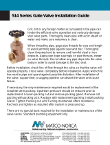
Notes
1) centerline of pump suction (inlet) to be
Slightly higher than centerline of suction
(Inlet) valve-so any air in suction system
Promptly reaches the pump and is expelled.
2) slope by-pass so low point drain will fully
Empty relief and choke valves and all
Liquid in by-pass circuit.
3) do not locate piping or other equipment
In front of or above pump liquid end-
Preventing servicing.
4) locate charging pump at point shown-if a
Charging pump is necessary (as for volatile
Fluids, for example.)
5) if desired, a two-way motor-operated by-pass
Valve may be used rather than a manual
Type. It should be designed to open
Automatically while starting or stopping.
6) feed line and by-pass line should feed
Liquid into tank below minimum liquid level.
Liquid
Supply
Tank
SUGGESTED PIPING SYSTEM FOR PLUNGER PUMPS
By-pass line
Full-opening suction (inlet) line valve
Low point drain valve
(See note 2)
Flexible hose or expansion
Joint (see note 7)
Needle or hard-trimmed choke by-pass valve-open to
Expel air in pump prior to loading (see note 5)
Full-opening relief valve or burst-disc
Valve-opens fully when set pressure is
Reached
Horizontal plunger pump with
Dual suction and dual discharge
Connections (driver and
Foundations not shown)
Pressure gauge and block valve
Discharge pulsation
Dampener (if used)
Suction pulsation
Dampener (if used)
Discharge line
(See note 7)
Full-opening discharge line valve
Swing check valve with full-opening seat
Pressure relief valve and
Cold weather drain
(See note 9)
Centerline of pump suction (inlet)
(See note 1)
Eccentric reducer with
Flat side up
Pressure gauge
And block valve
Flexible hose or
Expansion joint
(See note 7)
Suction (inlet) line-separate
Line required for each pump
If multiple pumping units ane
Used. Size of line depends on
Acceleration head factor
But must at least equal pump
Suction connection size.
(Minimum)
See note 4
Vortex splitter
And support
Suction bell-designed for low
Liquid entry velocity (may include
Foot valve if desirable)
Completely submerged bae
Plate separating incoming
From outgoing liquid
Manhole
Minimum
Liquid
Level
Feed line
(See note 6
)
7) to remove piping strain and vibration, a
Flexible hose, expansion joint, or swivel
Joint pair should be positioned to
Minimize effects of piping thermal
Expansion, contraction and piping weight.
8) suction and discharge piping must be
Supported and anchored.
9) to protect suction system against
Hazard of discharge pressure entry (as
When pump is idle) a small relief valve
Is often connected here.
10) all system conponents must have adequate
Pressure ratings for operating, starting,
And upset conditions in order to reduce
Potential hazards, particular attention
Is recommended for the surge condition
That will result downstream of the relief
Valve when normal discharge is blocked.

INSTALLATION
19 AP-03-100 (10-01-20)
APPROX. CENTER DISTANCE
(SPAN), INCHES
DEFLECTION,
INCHES
16" 1/4"
22" 3/8"
28" 7/16"
32" 1/2"
40" 5/8"
48" 3/4"
60" 15/16"
Belts must be matched in pitch length. If one or two belts are
slack, when the others are correctly tensioned, investigate
for possible reasons. Correct any misalignment or lack of
matching so each belt will transmit its load share.
Sheaves must be balanced to prevent abnormal vibration.
Balancing weights must not be removed. Type “QD” sheaves
must be evenly tightened on their tapered hubs to avoid rim
wobble and severe lateral vibration. V-belts which snap and
jerk will produce abnormal vibration and loads on both pump
and motor or engine.
Run the pump several minutes at full load with belt guard
re moved, observing for uneven motion on the belt slack side,
espe cially.
When an old V-belt drive becomes unserviceable, replace all
belts, not just the broken or cracked belts. Do not operate
belts on sheaves having worn, rusted, greasy or broken
grooves. Shut off power to driver before servicing drive or
pump.
Do not operate without appropiate guards in place.
DIRECTION OF ROTATION
Before placing pump in operation, check that crankshaft
rotation agrees with the arrows cast on top of the power
frame by briefly jogging the electric motor. Crankshaft
rotation must be clockwise as viewed from the right side of
pump.
If pump is gear driven, remember that the pinion shaft turns
opposite the crankshaft, if using a single-reduction geared
drive or in the same direction as the crankshaft when using a
planetary gear.
AUTOMATIC (SAFETY) SHUTDOWNS
Carefully check all electric shutdown devices present,
such as crankcase oil level, discharge pressure, vibration,
lubricator oil level, motor thermostat, etc.
CRANKSHAFT ASSEMBLY
GENERAL
Myers Aplex Series quintuplex crankshaft suspension utilizes
two single-row tapered bear ings, which are shim adjusted
to provide the correct running clearance and two journal
bearings on either side of the center connecting rod.
Thorough cleaning of all components prior to assembly is
essential. Power frame, shaft, bearings and retainer MUST be
scrupu lously scrubbed with clean solvent (such as kerosene)
before starting. Remove any oil, dirt, rust and foreign matter
which might prevent the correct fit up.
Crankshaft journals are critical. Remove all burrs, rust spots,
and nicks, paying special attention to the ground areas on
which bearings and oil seals operate.
TAPERED ROLLER BEARINGS
Shaft and frame tolerances provide a tight (press) fit on the
shaft and tap fit in the frame. The best way to install the cone
assembly (consisting of the inner race, cage and rollers) on
the shaft is to heat the cone assembly in an electric oven for
30 minutes at 300 to 400ºF. No More! (Do not heat bearings
with an acetylene torch. This ruins the bearings!) Using
clean, insulated gloves, remove the hot cone assembly from
the oven, promptly dropping it on to the shaft.
The cone assembly must contact the seat thrust face (not
be cocked) and the large end of the rollers must be down.
Do not hammer on the bearing. The soft steel cage is easily
distorted, ruining its function as a roller separator and guide
against skewing. If the cone does not contact its thrust
face properly, it must be pressed into place using a specially
machined sleeve (which does not touch the soft steel cage).
A hydraulic press is recom mended if this difficulty arises.
CENTER BEARINGS
The two center bearings are pressed into the powerframe
bore, one from the right and one from the left. The drilled
indentation on the bearing must be aligned with drilled and
tapped hole in the back of the power frame. After the bearing
is pressed into place, this indentation must approximately
line up to allow use of the locking set screw. Press into place
until the flange on the bearing faces out on the counter bore
in the powerframe. This ensures the bearing is not cocked.
After the bearings are in place, lock them with the set screw.
INSTALLING CRANKSHAFT
GENERAL
Stand the power frame casting on the floor or on a bench with
the fluid end face down and crankshaft end up. Insert one
bearing cup in the left frame cup bore and shoulder it against
the bearing retainer with a rubber mallet. Pass the crankshaft
through the right frame bore. Pass the crankshaft through
the center bearings and against the installed cup until the
bearing cone seats into the left bearing cup. Insert a second
bearing cup over the right hand crankshaft journal. Install
O-Ring on the crankshaft extension guard. Tap the guard
over the crankshaft extension if an auxiliary drive is not being
used.

INSTALLATION
20 AP-03-100 (10-01-20)
SHIM ADJUSTMENT OF TAPERED ROLLER
BEARINGS
To provide for crankshaft thermal expansion, sufficient shims
(located beneath bearing retainer flange) must be installed to
provide .005" to .015" lateral end play, when shaft is cold.
Separate the shims set (which consists of two .020"; three
.007"; and three .005" thick shims). Select one .020" shim
and the bearing retainer and position them over the bearing
retainer.
Insert two of six hex head cap screws 180º apart and tighten
alternately until the bearing cup is seat ed. Place a magnetic
base indicator on the exposed end of the crankshaft with
indicator spindle against the side of power frame. Move
crankshaft l a t e r a lly with a pry bar first left and then right,
observing movement indicated in each direction. The lateral
end play should be only .005" to .015". Remove the bearing
retainer and add shims as needed. Repeat the procedure
above until the proper end play tolerance is ob tained. Install
the remain ing four cap screws.
The recommended tightening torque for bearing retainer
1/2"-13UNC cap screws is 59 to 72 Ft. Lb.
INSTALLATION OF CRANKSHAFT OIL SEAL
Insert oil seal over the end of crankshaft and position it into
the oil seal bore in the power frame or bearing retainer. Using
a rubber mallet, tap it into the bore until the face of the seal is
flush with the power frame or bearing retainer.
CONNECTING ROD, CROSSHEAD AND CROSSHEAD
PIN ASSEMBLY:
GENERAL
Myers Aplex Series connecting rod assemblies employ
precision automotive type steel-backed, babbitt-lined
crankpin bearing halves which require no shims for clearance
adjustment. This pump employs full-circle (piston type)
crossheads.
Plungers are provided with a knurled wrenching area to
permit tight ening of the tapered thread into the crosshead,
establishing accurate alignment while affording easy field
installation.
Before beginning the assembly all parts must be scrupulously
cleaned, removing all oil, dirt, rust and foreign matter which
prevent proper fitting, or which might tend to score the
rubbing surfaces. Clean and examine the power frame bores
for scoring and abnormal wear, especially wear of the lower
crosshead guide way. Hone smooth, if rough.
Measure the bores of the frame using inside micrometers to
determine abnormal frame wear if any.
NEW CROSSHEAD OD:
3.243/3.246
NEW FRAME BORES:
3.253/3.250
NEW CROSSHEAD OD:
3.996/3.993
NEW FRAME BORES:
4.000/4.004
MA-45M MA-75L
SC-80 MA-75M
SC-80H MA-75H
SC-115
SC-115L
SC-115H
Frame bores which have become worn more than .015" must
be sleeved with a cast iron liner to re-establish correct
geometry and align ment. Contact Myers Aplex Series
concerning the repair of badly worn frame bores.
Smooth any rough corners and edges on the crosshead
skirts, using fine emery cloth. Examine and clean the female
tapered threads and wrist pin holes.
INSTALLING WRIST PIN BUSHINGS
The wrist pin bushing is precision machined bearing bronze
which is press fitted into the eye of the connecting rod.
BUSHING O.D.:
1.378/1.377
CONNECTING ROD EYE BORE:
1.3750/1.3760
BUSHING O.D.:
1.6280/1.6270 CONNECTING
ROD EYE BORE:
1.6250/1.6260
MA-45M MA-75L
SC-80 MA-75M
SC-80H MA-75H
SC-115
SC-115L
SC-115H
Carefully align the bushing with its hole and after applying oil
to bushing O.D. use a hydraulic press to force it home. When
a bronze bushing is pressed into place, the I.D. (bore) of the
bushing is reduced somewhat, owing to the extent of press
fit. Therefore, a clean, new wrist pin should be inserted into
the bushing bore to establish that running clearance has been
obtained. The running clearance between the wrist pin and
installed bushing is:
NEW PIN OD: 1.0640/1.0635
INSTALLED BUSHING BORE:
1.0645/1.0650
NEW PIN OD: 1.3140/1.3135
INSTALLED BUSHING BORE:
1.3145/1.3155
MA-45M MA-75M
SC-80 MA-75L
SC-80H MA-75H
SC-115
SC-115H
SC-115L
Oil Clearance .0005/.0015"
/