Page is loading ...

Installation and Operation Instructions
Unvented (Vent-Free) Linear Gas Fireplaces
P/N 126861-01 REV. P 01/2020
VRL4543ZEN
VRL4543ZEP
Models
PFS
®
US
Report No. F11-054
P126861-01
INSTALLER: Leave this manual with the appliance.
CONSUMER: Retain this manual for future reference.
This appliance may be installed in an aftermarket permanently located, manufactured (mobile) home,
where not prohibited by local codes. This appliance is only for use with the type of gas indicated on the
rating plate. This appliance is not convertible for use with other gases.
This is an unvented gas-fired heater. It uses air (oxygen) from the room in which it is installed. Provisions
for adequate combustion and ventilation air must be provided. Refer to Air for Combustion and Ventilation
section on Page 7 of this manual.
WARNING: If the information in this manual is not followed exactly, a fire or explosion may result
causing property damage, personal injury or loss of life.
– Do not store or use gasoline or other flammable vapors and liquids in the vicinity of this or any other
appliance.
– WHAT TO DO IF YOU SMELL GAS
• Do not try to light any appliance.
• Do not touch any electrical switch; do not use any phone in your building.
• Immediately call your gas supplier from a neighbor’s phone. Follow the gas supplier’s instructions.
• If you cannot reach your gas supplier, call the fire department.
– Installation and service must be performed by a qualified installer, service agency or the gas supplier.

SuperiorFireplaces.us.com
126861-01P
2
Thank you for your purchase. We appreciate your
business!
Please carefully read and follow all instructions in this manual. Pay
special attention to all warnings and safety information.
Following these safety, care, and operation instructions will help
ensure many years of dependable and enjoyable service from your
fireplace.
Please read and understand these instructions before installing
or operating.
SAFETY
WARNING: This is an unvented gas-fired heater.
It uses air (oxygen) from the room in which it is
installed. Provisions for adequate combustion and
ventilation air must be provided. Refer to Air for
Combustion and Ventilation section on Page 6 of this
manual.
WARNING: Vent-free products are prohibited for
bedroom and bathroom installation in the Common-
wealth of Massachusetts.
These appliances comply with National Safety
Standards and are listed by PFS TECO to ANSI
Z21.11.2 as unvented Gas-fired room heaters.
This appliance may be installed in an aftermarket,*
permanently located, manufactured (mobile) home,
where not prohibited by local codes.
This appliance is only for use with the type of gas
indicated on the rating plate. This appliance is not
convertible for use with other gases.
IMPORTANT: Read this owner’s manual carefully and
completely before trying to assemble, operate or ser-
vice this heater. Improper use of this heater can cause
serious injury or death from burns, fire, explosion,
electrical shock and carbon monoxide poisoning.
* Aftermarket: Completion of sale, not for purpose of resale, from
the manufacturer
WARNING: FIRE, EXPLOSION, AND ASPHYXIATION
HAZARD
Improper adjustment, alteration, service, mainte-
nance, or installation of this heater or its controls can
cause death or serious injury.
Read and follow instructions and precautions in User’s
Information Manual provided with this heater.
TABLE OF CONTENTS
Safety ............................................................................................. 2
Local Codes ................................................................................... 4
Requirements for the Commonwealth of Massachusetts............... 4
Product Identification ..................................................................... 4
Product Features ............................................................................ 5
Air for Combustion and Ventilation ................................................ 6
Installation ..................................................................................... 8
Gas Control Module System ........................................................ 16
Remote Control Operation ........................................................... 17
Operating Fireplace ...................................................................... 20
Cleaning and Maintenance .......................................................... 21
Inspecting Burners ...................................................................... 22
Specifications ............................................................................... 22
Wiring Diagram ............................................................................ 23
Troubleshooting ........................................................................... 24
Parts ............................................................................................ 27
Replacement Parts ....................................................................... 30
Service Hints ................................................................................ 30
Technical Service ......................................................................... 30
Accessories .................................................................................. 30
Warranty ...................................................................................... 31
Any safety screen, guard, or barrier removed for ser-
vicing an appliance must be replace prior to operating
the heater. The firescreen or guard designed for this
unvented appliance must be installed prior to operation.
WARNING: This product can expose you to chemicals
including Carbon Black, which is known to the State
of California to cause cancer, and Carbon Monoxide,
which is known to the State of California to cause birth
defects or other reproductive harm. For more informa-
tion go to www.P65Warnings.ca.gov

SuperiorFireplaces.us.com
126861-01P
3
SAFETY Continued
WARNING: Do not use a blower insert, heat ex-
changer insert or other accessory not approved for
use with this heater.
Due to high temperatures, the appliance should be
located out of traffic and away from furniture and
draperies.
Do not place clothing or other flammable material on
or near the appliance. Never place any objects on the
heater.
You must operate appliance with the fireplace screen and
hood in place before running heater. The fireplace screen
shall have openings for introduction of combustion air.
Children and adults should be alerted to the hazard
of high surface temperature and should stay away to
avoid burns or clothing ignition. Heater will remain
hot for a time after shutdown. Allow surface to cool
before touching.
Keep the appliance area clear and free from combus-
tible materials, gasoline and other flammable vapors
and liquids.
Installation and repair should be done by a qualified
service person. The appliance should be inspected
before use and at least annually by a professional
service person. More frequent cleaning may be re-
quired due to excessive lint from carpeting, bedding
material, etc. It is imperative that control compart-
ments, burners, and circulating air passageways of
the appliance be kept clean.
This appliance must be mounted on a fully supported
base extending the full width and depth of the unit.
The fireplace may be located on or near conventional
construction materials. However, if installed on com-
bustible materials, such as carpeting, vinyl tile or other
combustible material other than wood flooring, the
appliance shall be installed on a metal or wood panel
extending the full width and depth of the appliance.
Fireplaces become very hot when running fireplace.
WARNING: Young children should be carefully
supervised when they are in the same room with the
appliance. When using the hand-held remote acces-
sory, keep selector switch in the OFF position to prevent
children from turning on burners with remote.
WARNING: Do not allow fans to blow directly into
the fireplace. Avoid any drafts that alter burner flame
patterns. Ceiling fans can create drafts that alter
burner flame patterns. Altered burner patterns can
cause sooting.
WARNING: Any change to this heater or its con-
trols can be dangerous.
DANGER: Carbon monoxide poisoning may lead
to death!
Carbon Monoxide Poisoning: Early signs of carbon monoxide poison-
ing resemble the flu, with headaches, dizziness or nausea. If you have
these signs, the heater may not be working properly. Get fresh air at
once! Have heater serviced. Some people are more affected by carbon
monoxide than others. These include pregnant women, people with
heart or lung disease or anemia, those under the influence of alcohol
and those at high altitudes.
Natural and Propane/LP Gas: Natural and propane/LP gases are
odorless. An odor-making agent is added to the gas. The odor helps
you detect a gas leak. However, the odor added to the gas can fade.
Gas may be present even though no odor exists.
Make certain you read and understand all warnings. Keep this
manual for reference. It is your guide to safe and proper operation
of this heater.
Solid-fuels shall not be burned in a fireplace in which
an unvented room heater is installed.
WARNING: Do not place log scraps or volcanic
stone on burner.

SuperiorFireplaces.us.com
126861-01P
4
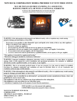
PRODUCT IDENTIFICATION
Figure 1 - Vent Free VRL4543 Fireplace
2. Do not place propane/LP supply tank(s) inside any structure.
Locate propane/LP supply tank(s) outdoors (propane/LP only).
3. If you smell gas
• shut off gas supply
• do not try to light any appliance
• do not touch any electrical switch; do not use any phone in your
building
• leave the building immediately
• immediately call your gas supplier from a neighbor’s phone.
Follow the gas supplier’s instructions
• if you cannot reach your gas supplier, call the fire department
4. This fireplace shall not be installed in a bedroom or bathroom.
5. Do not use this fireplace as a wood-burning fireplace. Use only
the logs provided with the fireplace.
6. Do not add extra logs or ornaments such as pine cones, vermicu-
lite, or rock wool. Using these added items can cause sooting.
Do not add lava rock around base. Rock and debris could fall into
the control area of fireplace.
7. This fireplace is designed to be smokeless. If logs ever appear
to smoke, turn off fireplace and call a qualified service person.
NOTE: During initial operation, slight smoking could occur due
to log curing and fireplace burning manufacturing residues.
8. To prevent the creation of soot, follow the instructions in Cleaning
and Maintenance, Page 21.
9. Before using furniture polish, wax, carpet cleaner, or similar
products, turn heater off. If heated, the vapors from these prod-
ucts may create a white powder residue within burner box or on
adjacent walls or furniture.
10. This fireplace needs fresh air ventilation to run properly. This
fireplace has an Oxygen Depletion Sensing (ODS) safety shutoff
system. The ODS shuts down the fireplace if not enough fresh
air is available. See Air for Combustion and Ventilation, Page 6.
If fireplace keeps shutting off, see Troubleshooting, Page 24.
11. Do not run fireplace
• where flammable liquids or vapors are used or stored.
• under dusty conditions.
12. Do not use this fireplace to cook food or burn paper or other
objects.
13. Do not use fireplace if any part has been under water. Immediately
call a qualified service technician to inspect the room fireplace
and to replace any part of the control system and any gas control
which has been under water.
14. Turn off and unplug fireplace and let cool before servicing. Only
a qualified service person should service and repair fireplace.
15. Operating fireplace above elevations of 4,500 feet could cause
pilot outage.
16. To prevent performance problems, do not use propane/LP fuel
tank of less than 100 lbs. capacity (propane/LP only).
17. Provide adequate clearances around air openings.
18. The screen or any other part removed for servicing must be
replaced prior to operating this heater.
1. WARNING: This appliance is only for use with the type of gas
indicated on the rating plate. This appliance is not convert-
ible for use with other gases.
SAFETY Continued
Pebble Pan
Access Door
Top Spacers
Left Side
Right Side
Front
Nailing
Flange

SuperiorFireplaces.us.com
126861-01P
5
LOCAL CODES
Install and use appliance with care. The installation must conform
with local codes or in the absence of local codes, to the latest edition
of The National Fuel Gas Code, ANSI Z223.1/NFPA 54*.
*Available from:
American National Standards Institute, Inc.
25 West 43rd Street, 4th floor
New York, NY 10036
National Fire Protection Association, Inc.
1 Batterymarch Park
Quincy, MA 02169-7471
Firebox must be electrically grounded in accordance with the National
Electrical Code, ANS/NFPA70 (latest edition).
Listing: These fireplaces comply with the National Safety Standards
and are listed by PFS TECO to ANSI Z21.11.2 as unvented Gas-fired
room heaters.
COMMONWEALTH OF MASSACHUSETTS REQUIRE-
MENTS
These appliances are approved for installation in the US state of
Massachusetts if the following additional requirements are met:
• Un-vented Room Heaters shall be installed in accordance with
527 CMR 30.
• Installation and repair must be done by a plumber or gas fitter
licensed in the Commonwealth of Massachusetts.
• The flexible gas line connector used shall not exceed 36 inches
(92 centimeters) in length.
• The individual manual shut-off must be a T-handle type valve.
• Un-vented appliances may NOT be installed in bedrooms or
bathrooms.
• A working smoke detector must be installed in the area where
vent-free appliances are installed.
Seller of un-vented propane or natural gas-fired supplemental room
heaters shall provide to each purchaser a copy of 527 CMR 30 upon
sale of the unit.
PRODUCT FEATURES
OPERATION
This vent-free fireplace is clean burning. It requires no outside
venting. There is no heat loss out a vent or up a chimney. Heat is
generated by both realistic flames. This heater is designed for vent-
free operation. It has been tested and approved to ANSI Z21.11.2
standard for unvented heaters. State and local codes in some areas
prohibit the use of vent-free heaters.
SAFETY DEVICE
This fireplace has a pilot with an Oxygen Depletion Sensing (ODS)
safety shutoff system. The ODS/pilot is a required feature for vent-free
room heaters. The ODS/pilot system shuts off the fireplace if there is
not enough fresh air.

SuperiorFireplaces.us.com
126861-01P
6
AIR FOR COMBUSTION AND VENTILATION
Unusually tight construction is defined as construction where:
a. walls and ceilings exposed to the outside atmosphere have a
continuous water vapor retarder with a rating of one perm (6 x
10
-11
kg per pa-sec-m
2
) or less with openings gasketed or sealed
and
b. weather stripping has been added on openable windows and
doors and
c. caulking or sealants are applied to areas such as joints around
window and door frames, between sole plates and floors, be-
tween wall-ceiling joints, between wall panels, at penetrations
for plumbing, electrical and gas lines and at other openings.
If your home meets all of the three criteria above, you must provide
additional fresh air. See Ventilation Air From Outdoors, Page 7.
If your home does not meet all of the three criteria above, proceed to
Determining Fresh-Air Flow For Heater Location, Page 7.
Confined and Unconfined Space
The National Fuel Gas Code, ANSI Z223.1/ NFPA54 allows two meth-
ods for determining whether the space in which the heater is being
installed is confined or unconfined space. The standard method defines
a confined space as a space whose volume is less than 50 cubic feet
per 1,000 Btu per hour (4.8 m
3
per kw) of the aggregate input rating
of all appliances installed in that space and an unconfined space as a
space whose volume is not less than 50 cubic feet per 1,000 Btu per
hour (4.8 m
3
per kw) of the aggregate input rating of all appliances
installed in that space. Rooms communicating directly with the space
in which the appliances are installed*, through openings not furnished
with doors, are considered a part of the unconfined space.
This appliance shall not be installed in a confined space or unusually
tight construction unless provisions are provided for adequate com-
bustion and ventilation air.
Where the air infiltration rate of a structure is known, the Known Air
Infiltration Rate Method may be used. Follow The National Fuel Gas
Code, ANSI Z223.1/NFPA 54 to use this method to determine if the
space is confined or unconfined.
* Adjoining rooms are communicating only if there are doorless
passageways or ventilation grills between them.
WARNING: This heater shall not be installed in a
room or space unless the required volume of indoor
combustion air is provided by the method described
in the National Fuel Gas Code, ANSI Z223.1/NFPA 54,
the International Fuel Gas Code, or applicable local
codes. Read the following instructions to ensure proper
fresh air for this and other fuel-burning appliances
in your home.
Today’s homes are built more energy efficient than ever. New materials,
increased insulation and new construction methods help reduce heat
loss in homes. Homeowners apply weather strip and caulk around
windows and doors to keep the cold air out and the warm air in. During
heating months, homeowners want their homes as airtight as possible.
While it is good to make your home energy efficient, your home
needs to breathe. Fresh air must enter your home. All fuel-burning
appliances need fresh air for proper combustion and ventilation.
Exhaust fans, some fireplaces, clothes dryers and some fuel-burning
appliances draw air from the house to operate. You must provide ad-
equate fresh air for these appliances. This will ensure proper venting
of vented fuel-burning appliances.
PROVIDING ADEQUATE VENTILATION
The following are excerpts from National Fuel Gas Code, ANSI Z223.1/
NFPA 54, Air for Combustion and Ventilation.
All spaces in homes fall into one of the three following ventilation
classifications:
1. Unusually Tight Construction
2. Unconfined Space
3. Confined Space
The information on Pages 6 through 7 will help you classify your
space and provide adequate ventilation.
Unusually Tight Construction
The air that leaks around doors and windows may provide enough
fresh air for combustion and ventilation. However, in buildings of
unusually tight construction, you must provide additional fresh air.

SuperiorFireplaces.us.com
126861-01P
7
DETERMINING FRESH-AIR FLOW FOR FIREPLACE LOCATION
Determining if You Have a Confined or Unconfined Space Using
the Standard Method
Use this work sheet to determine if you have a confined or uncon-
fined space.
Space: Includes the room in which you will install fireplace plus any
adjoining rooms with doorless passageways or ventilation grills between
the rooms.
1. Determine the volume of the space (length x width x height).
Length x Width x Height =__________cu. ft. (volume of space)
Example: Space size 20 ft. (length) x 16 ft. (width) x 8 ft. (ceiling
height) = 2,560 cu. ft. (volume of space)
If additional ventilation to adjoining room is supplied with grills
or openings, add the volume of these rooms to the total volume
of the space.
2. Multiply the space volume by 20 to determine the maximum Btu/
Hr the space can support.
_______ (volume of space) x 20 = (Maximum Btu/Hr the space
can support)
Example: 2,560 cu. ft. (volume of space) x 20 = 51,200 (maximum
Btu/Hr the space can support)
3. Add the Btu/Hr of all fuel burning appliances in the space.
Vent-free fireplace ________Btu/Hr
Gas water heater* ________Btu/Hr
Gas furnace ________Btu/Hr
Vented gas heater ________Btu/Hr
Gas fireplace logs ________Btu/Hr
Other gas appliances*+ ____Btu/Hr
Total =_______Btu/Hr
* Do not include direct-vent gas appliances. Direct-vent draws
combustion air from the outdoors and vents to the outdoors.
Example:
Gas water heater 40,000 Btu/Hr
Vent-free fireplace + 33,000 Btu/Hr
Total = 73,000 Btu/Hr
4. Compare the maximum Btu/Hr the space can support with the actual
amount of Btu/Hr used.
______ Btu/Hr (maximum the space can support)
______ Btu/Hr (actual amount of Btu/Hr used)
Example: 51,200 Btu/Hr (maximum the space can support)
73,000 Btu/Hr (actual amount of Btu/Hr used)
The space in the example is a confined space because the actual Btu/
Hr used is more than the maximum Btu/Hr the space can support.
You must provide additional fresh air. Your options are as follows:
A. Rework worksheet, adding the space of an adjoining room. If the
extra space provides an unconfined space, remove door to adjoining
room or add ventilation grills between rooms. See Ventilation Air
From Inside Building.
B. Vent room directly to the outdoors. See Ventilation Air From
Outdoors.
C. Install a lower Btu/Hr fireplace, if lower Btu/Hr size makes room
unconfined.
If the actual Btu/Hr used is less than the maximum Btu/Hr the
space can support, the space is an unconfined space. You will need
no additional fresh air ventilation.
WARNING: If the area in which the heater may be
operated does not meet the required volume for indoor
combustion air, combustion and ventilation air shall
be provided by one of the methods described in the
National Fuel Gas Code, ANSI Z223.1/NFPA 54, the
International Fuel Gas Code, or applicable local codes.
VENTILATION AIR
Ventilation Air From Inside Building
This fresh air would come from an adjoining unconfined space. When
ventilating to an adjoining unconfined space, you must provide two
permanent openings: one within 12" of the ceiling and one within
12" of the floor on the wall connecting the two spaces (see options
1 and 2, Figure 2). You can also remove door into adjoining room
(see option 3, Figure 2). Follow the National Fuel Gas Code, ANSI
Z223.1/NFPA 54, Air for Combustion and Ventilation for required size of
ventilation grills or ducts.
AIR FOR COMBUSTION AND VENTILATION Continued
Ventilation Air From Outdoors
Provide extra fresh air by using ventilation grills or ducts. You must
provide two permanent openings: one within 12" of the ceiling and one
within 12" of the floor. Connect these items directly to the outdoors or
spaces open to the outdoors. These spaces include attics and crawl
spaces. Follow the National Fuel Gas Code, ANSI Z223.1/NFPA 54, Air for
Combustion and Ventilation for required size of ventilation grills or ducts.
IMPORTANT: Do not provide openings for inlet or outlet air into attic
if attic has a thermostat-controlled power vent. Heated air entering
the attic will activate the power vent.
Figure 3 - Ventilation Air from Outdoors (Fireplace may differ
from actual model)
Figure 2 - Ventilation Air from Inside Building (Fireplace may
differ from actual model)
Outlet
Air
Ventilated
Attic
Outlet
Air
Inlet
Air
Inlet Air
Ventilated
Crawl Space
To
Crawl
Space
To Attic
Or
Remove
Door into
Adjoining
Room,
Option
3
Ventilation Grills
Into Adjoining Room,
Option 2
Ventilation
Grills
Into Adjoining
Room,
Option 1
12"
12"

SuperiorFireplaces.us.com
126861-01P
8
INSTALLATION
NOTICE: This appliance is intended for supplemental
heating. Use this heater along with your primary heat-
ing system. Do not install this heater as your primary
heat source. If you have a central heating system,
you may run system’s circulating blower while using
heater. This will help circulate the heat throughout
the house.
WARNING: A qualified service person must install
fireplace. Follow all local codes.
WARNING: Never install the fireplace
• in a bedroom or bathroom
• in a recreational vehicle
• where curtains, furniture, clothing or other flam-
mable objects are less than 36" from the front and
42" top of fireplace. For side clearances see Figure
7, Page 9
• in high traffic areas
• in windy or drafty areas
CAUTION: This fireplace creates warm air cur-
rents. These currents move heat to wall surfaces next
to fireplace. Installing fireplace next to vinyl or cloth
wall coverings or operating heater where impurities
(such as, but not limited to, tobacco smoke, aromatic
candles, cleaning fluids, oil or kerosene lamps, etc.)
in the air exist, may discolor walls or cause odors.
NOTE: Standoff spacers are attached to the sides and top of your
fireplace, these spacers can be placed directly against wall or fram-
ing materials.
Use the dimensions shown for rough openings to create the easiest
installation as shown in Figure 4.
IMPORTANT: Vent-free heaters add moisture to the air. Although this
is beneficial, installing fireplace in rooms without enough ventilation
air may cause mildew to form from too much moisture. See Air for
Combustion and Ventilation, Page 6.
CHECK GAS TYPE
Use the correct gas type (natural or propane/LP) for your fire-
place. If your gas supply is not correct, do not install fireplace.
Call dealer where you bought fireplace for proper type fireplace.
WARNING: This appliance is equipped for either
natural gas or propane/LP gas but not both. Gas type
is indicated on the rating plate. Field conversion is
not permitted.
INSTALLATION CLEARANCES
WARNING: Maintain the minimum clearances. If
you can, provide greater clearances from floor, ceiling
and adjoining wall.
Carefully follow the instructions below. This will ensure safe instal-
lation.
CLEARANCES
Minimum clearances to combustibles for the fireplace are as follows:
*Back and sides 1"
Perpendicular walls 8"
Floor (From bottom of Fireplace) 0"
Ceiling (From top of opening) 42"
Top of Standoffs 0"
* For back and sides of fireplace, do not pack with insulation or
other materials.
Maintain adequate clearances for accessibility for purposes of
servicing and proper operation.
FRAMING AND FINISHING
Choose framing application accordingly. Figure 4, Page 9 shows
typical one sided framing. Figure 5, Page 9 shows framing for
see-thru installation. NOTE: Kits F1029 and F1030 are required
for see-thru application (See upgrading VRL4543 to see-thru ap-
plication, Page 14).
All minimum clearances must be met. Steel framing may be neces-
sary or wood studs may be notched. Concrete board is provided for
facing around the fireplace as shown in Figure 6, Page 9.
If you are using a separate combustible mantel piece, refer to
Figure 7, Page 9 for proper installation height. You can install
noncombustible mantels at any height above the fireplace.
NOTE: To avoid heat-related finish damage, we recommend
the use of high temperature paint (rated 175° F or higher) on
the underside of the mantel.
Minimum clearance requirements include any projections such as
shelves, window sills, mantels, etc. above the appliance.
Hearth Extension
A hearth extension is not required with this fireplace. Any hearth
extension used is for appearance only and does not have to conform
to standard hearth extension installation requirements.

SuperiorFireplaces.us.com
126861-01P
9
53
1
/
4
"
38"
*53
1
/
4
"
38"
STUDS MOUNTED (FLAT)
INSIDE OF NAILING FLANGE
15
1
/
4
"
MOUNTED INSIDE OF
NAILING FLANGE (FLA
T)
FOR ONE SIDED
APPLICATION, STUDS
ARE NOT MOUNTED
TO THE REAR
OF NAILING FLANGES
17
1
/
2
"
INSTALLATION Continued
Figure 5 - Framing Clearances for See-Thru Application
Ref.
Mantel
Depth Ref.
Mantel
from Top
of Opening
1 12" A 24"
2 9" B 21"
3 6" C 18"
4 4" D 16"
5 2" E 14"
A
B
C
D
E
1
2
3
4
5
Wall
Supplied firebox
hood must be
used at all times.
Note: All vertical
measurements are
from top of fireplace
hood opening to
bottom of mantel
shelf.
Noncombustible
material ma
y project
off this sur
face above
the fireb
ox hood
Figure 6 - Installing Concrete Board
Concrete
Board
Figure 4 - Framing Clearances for One Sided Application
*Please refer to overall fireplace width (Figure 8, Page 10) before
rough framing construction.
Figure 7 - Clearances for Combustible Mantels
TOP VIEW
SAFE
ZONE
Perpendicular
Wall
Combustible
Material May
Be Used
33°
8"
to Face Opening
5"

SuperiorFireplaces.us.com
126861-01P
10
17
1
/
2
"
29
5
/
8
"
29
5
/
8
"
16
3
/
8
"
7
1
/
8
"
1
7
/
8
"
8
1
/
4
"
44
1
/
8
"
1"
1"
55
1
/
8
"
52"
47"
16
1
/
2
"
11
3
/
4
"
8
1
/
4
"
5
/
8
"
INSTALLATION Continued
Figure 8 - VRL4543 Series Dimensions
Electrical
Outlet
Gas Line
Access
Gas Line
Access
Top View
Front View
Right Side
Left Side

SuperiorFireplaces.us.com
126861-01P
11
INSTALLATION Continued
Figure 9 - Connecting Electricity
Electrical
Bushing
Electrical
Cover Plate
Electrical
Housing
Wire Nut (3x)
(Not Supplied)
Outer Wrapper
of Fireplace
Electrical Cover Plate
and Electrical Bushing
To Power
Source
Receptacle
(Supplied)
Power Source Wiring
(Not Supplied)
Ground
(16GA Green)
Sheet Metal
Screws
14GA
Black &
White
WARNING: A qualified service person must con-
nect fireplace to gas supply. Follow all local codes.
CAUTION: Never connect propane/LP fireplace di-
rectly to the propane/LP supply. This fireplace requires
an external regulator (not supplied). Install the external
regulator between the fireplace and propane/LP supply.
WARNING: Never connect this appliance to private
(non-utility) gas wells. This gas is commonly known
as wellhead gas and does not have odorants and may
have impurities, and variations in BTU content. The
use of well-head gas will void the manufacturer’s
warranty to this appliance.
INSTALLING GAS PIPING TO FIREPLACE LOCATION
CHECK GAS TYPE
Use proper gas type for the fireplace unit you are installing. If you
have conflicting gas types, do not install fireplace. See retailer where
you purchased the fireplace for proper fireplace according to your
gas type.
CAUTION: Use only new, black iron or steel pipe.
Internally-tinned copper tubing may be used in certain
areas. Check your local codes. Use pipe of 1/2" diam-
eter or greater to allow proper gas volume to fireplace.
If pipe is too small, undue loss of volume will occur.
Installation Items Needed
Before installing fireplace, make sure you have the items listed below.
• external regulator for propane/LP unit only (supplied by installer)
• piping (check local codes)
• sealant (resistant to propane/LP gas)
• equipment shutoff valve *
• test gauge connection *
• sediment trap (optional)
• tee joint
• pipe wrench
• approved flexible gas line with gas connector (if allowed by local
codes) (not provided)
* An equipment shutoff valve with 1/8" NPT tap is an acceptable al-
ternative to test gauge connection. Purchase the optional equipment
shutoff valve from your dealer.
For propane/LP units, the installer must supply an external regulator.
The external regulator will reduce incoming gas pressure. You must
reduce incoming gas pressure to between 11" and 14" of water. If
you do not reduce incoming gas pressure, heater regulator damage
could occur. Install external regulator with the vent pointing down
as shown in Figure 10, Page 12. Pointing the vent down protects it
from freezing rain or sleet.
NOTICE: If your installation does not meet the
minimum clearances shown, you must do one of
the following:
• raise the mantel to an acceptable height
• remove the mantel
NOTICE: Surface temperatures of adjacent walls and
mantels become hot during operation. Walls and
mantels above the firebox may become hot to the
touch. If installed properly, these temperatures meet
the requirement of the national product standard. Fol-
low all minimum clearances shown in this manual.
Mantel Clearances for Built-In Installation
If placing mantel above built-in fireplace, you must meet minimum
clearance between mantel shelf and top of fireplace opening.
ELECTRICAL WIRING INSTRUCTIONS
1. Remove electrical cover plate with bushing from left side of
fireplace front by removing 2 sheet metal screws as shown in
Figure 9.
2. Slide power source wiring through electrical bushing opening
and electrical cover plate and make all necessary connections.
3. Slide all wiring connections in electrical housing as shown in
Figure 9.
4. Secure electrical cover plate with screws previously removed.
NOTE: Electrical housing and cover plate have sharp edges. Wear
protective gloves.

SuperiorFireplaces.us.com
126861-01P
12
INSTALLATION Continued
Figure 10 - External Regulator on Propane/LP Supply Tank with
Vent Pointing Down
External
Regulator
Vent
Pointing
Down
Propane/LP
Supply Tank
Installation must include an equipment shutoff valve, union and
plugged 1/8" NPT tap. Locate NPT tap within reach for test gauge
hook up. NPT tap must be upstream from fireplace (see Figure 10).
IMPORTANT: Install equipment shutoff valve in an accessible loca-
tion. The equipment shutoff valve is for turning on or shutting off
the gas to the appliance.
Check your building codes for any special requirements for locating
equipment shutoff valve to fireplaces.
Apply pipe joint sealant lightly to male NPT threads. This will prevent
excess sealant from going into pipe. Excess sealant in pipe could
result in clogged fireplace valves. Never use sealant on flare threads.
WARNING: Use pipe joint sealant that is resistant
to liquid petroleum (LP) gas.
We recommend that you install a sediment trap in supply line as
shown in Figure 11. Locate sediment trap where it is within reach for
cleaning. Install in piping system between fuel supply and fireplace.
Locate sediment trap where trapped matter is not likely to freeze. A
sediment trap traps moisture and contaminants. This keeps them
from going into fireplace gas controls. If sediment trap is not installed
or is installed wrong, fireplace may not run properly.
Figure 11 - Gas Connection
* Purchase the optional equipment shutoff valve from your dealer.
** Minimum inlet pressure for purpose of input adjustment.
Sediment Trap
3" Minimum
Cap Pipe Tee
Nipple Joint
Equipment Shutoff Valve
With 1/8" NPT Tap*
Natural Gas
From Gas Meter
(5" W.C.** to 10.5"
W.C. Pressure)
Propane/LP
From External
Regulator
(11" W.C.** to 14"
W.C. Pressure)
CONNECTING FIREPLACE TO GAS SUPPLY
Installation Items Needed
• 5/16" hex socket wrench or nut-driver
• sealant (resistant to propane/LP gas, not provided)
1. Route flexible gas line (provided by installer) from equipment
shutoff valve to fireplace. Route flexible gas supply line through
one of the access holes on side of fireplace.
2. Attach flexible gas line from gas supply to control valve (see
Figure 12).
3. Check all gas connections for leaks. See Checking Gas Connec-
tions, Page 13.
Figure 12 - Connecting Incoming Gas Line to Flex Gas Line
NOTE:
1) Wire connections not shown for clarity
2) * 1/8" NPT Plugged Tapping
MAIN
IN
OUT
PILOTADJ
PILOT
Inlet Pressure Tap
Outlet Pressure Tap
Gas Shutoff Valve
Flexible Gas Line Do
NOT Kink
1/2" NPT Incoming Gas Line
Set Screw

SuperiorFireplaces.us.com
126861-01P
13
INSTALLATION Continued
Figure 13 - Equipment Shutoff Valve
Open
Closed
Equipment
Shutoff Valve
Figure 14 - Checking Gas Joints for Propane/LP Gas Fireplace
Propane/LP
Supply Tank
Gas Valve
Equipment
Shutoff Valve
Gas Meter
Gas Valve
Equipment Shutoff Valve
Figure 15 - Checking Gas Joints for Natural Gas Fireplace
PRESSURE TESTING FIREPLACE GAS CONNECTIONS
1. Open equipment shutoff valve (see Figure 13).
2. Open main gas valve located on or near gas meter for natural gas
or open propane/LP supply tank valve.
3. Make sure control knob of fireplace is in the OFF position.
4. Check all joints from equipment shutoff valve to gas control valve
(see Figures 14 or 15). Apply noncorrosive leak detection fluid
to all joints. Bubbles forming show a leak.
5. Correct all leaks at once.
6. Light fireplace (see Operating Fireplace, Page 20). Check all other
internal joints for leaks.
7. Turn off fireplace (see To Turn Off Gas to Appliance, Page 20).
CHECKING GAS CONNECTIONS
WARNING: Test all gas piping and connections,
internal and external to unit, for leaks after installing
or servicing. Correct all leaks at once.
WARNING: Never use an open flame to check for
a leak. Apply a noncorrosive leak detection fluid to
all joints. Bubbles forming show a leak. Correct all
leaks at once.
CAUTION: Make sure external regulator has been
installed between propane/LP supply and fireplace.
See guidelines under Connecting Fireplace to Gas
Supply.
The appliance and its appliance main gas valve must be disconnected
from the gas supply piping system during any pressure testing of
that system at test pressures in excess of 1/2 psi (3.5 kPa).
The appliance must be isolated from the gas supply piping system
by closing its equipment shutoff valve during any pressure testing of
the gas supply piping system at test pressures equal to or less than
1/2 psi (3.5 kPa).
PRESSURE TESTING GAS SUPPLY PIPING SYSTEM
Test Pressures In Excess Of 1/2 PSIG (3.5 kPa)
1. Disconnect fireplace with its appliance main gas valve (control
valve) and equipment shutoff valve from gas supply piping
system. Pressures in excess of 1/2 psig (3.5 kPa) will damage
fireplace regulator.
2. Cap off open end of gas pipe where equipment shutoff valve was
connected.
3. Pressurize supply piping system by either opening propane/LP
supply tank valve for propane/LP gas or opening main gas valve
located on or near gas meter for natural gas or using compressed
air.
4. Check all joints of gas supply piping system. Apply noncorrosive
leak detection fluid to all joints. Bubbles forming show a leak.
5. Correct all leaks at once.
6. Reconnect fireplace and equipment shutoff valve to gas supply.
Check reconnected fittings for leaks.
Test Pressures Equal To or Less Than 1/2 PSIG (3.5 kPa)
1. Close equipment shutoff valve (see Figure 13).
2. Pressurize supply piping system by either opening propane/LP
supply tank valve for propane/LP gas or opening main gas valve
located on or near gas meter for natural gas or using compressed
air.
3. Check all joints from gas meter to equipment shutoff valve for natural
gas or propane/LP supply to equipment shutoff valve for propane/
LP (see Figures 14 or 15). Apply noncorrosive leak detection fluid
to all joints. Bubbles forming show a leak.
4. Correct all leaks at once.

SuperiorFireplaces.us.com
126861-01P
14
INSTALLATION Continued
FINISHING FIREPLACE FOR INSTALLATION
VRL4543 series fireplace come with the rear panel semi-installed.
If you will be using the fireplace for a one sided regular application,
you will need to finish the installation of the rear panel. If you will be
upgrading the fireplace to a see-thru, the rear panel will need to be
removed (See Upgrading VRL4543 to See-Thru Application).
1. Using self-tapping screws provided and holes on rear panel as a
guide, screw the rear panel to the fireplace as shown in Figure
16.
INSTALLING HOOD
1. Loosen screws at top of face opening and slide hood through
screws as shown in Figure 17.
2. Tighten screws securing hood to fireplace.
Figure 16 - Installing Rear Panel for Regular Applications
Figure 18 - Removing Rear Panel for See-Thru Applications
Figure 19 - Removing for See-Thru ApplicationsFigure 17 - Installing Hood
UPGRADING VRL4543 TO SEE-THRU APPLICATION
Removing Rear Panel
1. In the rear of the fireplace, locate screws at top of rear panel and
remove as shown in Figure 18. Discard screws and rear panel.
2. Unscrew mount bracket from top face as shown in Figure 19.
Discard mounting bracket and replace screws.

SuperiorFireplaces.us.com
126861-01P
15
INSTALLATION Continued
Removing False Door
1. In the rear of the fireplace, Unlock 3 door latches on top of
firebox using your fingers or the latch opener provided.
2. Hook opener over latch as shown in Figure 20. Swing the
bottom of the opener down toward the door. You will not need
to pull down.
3. Tilt open false door 45° from the top of firebox and lift up to release
door from retaining channel.
Figure 21 - Removing Rear Interior Wall for See-Thru
Applications
Rear Panel
Side Panel
Bracket
Figure 20 - Latch Opener
Figure 22 - Installing Access Door Retaining Brackets for See-
Thru Applications
Retaining Bracket
Figure 23 - Installing Side Face Filler for See-Thru
Applications
Removing Rear Interior Wall
1. Through firebox opening in the front of the fireplace, unscrew 4
corner brackets from the firebox top (See Figure 21).
2. Remove 2 side walls and then the rear wall. Discard rear wall.
3. Replace 2 side walls and reinstall the corner brackets.
Installing Access Door Retaining Brackets
1. Screw access door retaining brackets into the inner side face using
2 screws on both the left and right side as shown in Figure 22.
Installing Side Face Filler
1. Screw side face filler into firebox side baffle using 2 screws on
both the left and right side as shown in Figure 23.
Installing Access Door
1. Place access door in front of fireplace opening with the slanted
side facing forward. The slanted surface will slide underneath the
flange of the bottom face Insert tabs on side of access door into
slots on retaining brackets (See Figure 24).
Installing Hood
1. If required, install hood as shown on Figure 17, Page 14.
Figure 24 - Access Door for See-Thru Applications
Access Door
Flange on Face
Bottom
Side Filler
Retaining
Bracket

SuperiorFireplaces.us.com
126861-01P
16
INSTALLATION Continued
GLASS PEBBLE INSTALLATION
WARNING: Do not change or substitute glass
pebbles provided with this fireplace. If replacing, use
only replacement glass pebbles. See Parts Page 28.
WARNING: Do not block pilot ports with glass
pebbles.
WARNING: Do not place the glass pebbles on
the burner, only on the burner tray as illustrated in
Figure 25.
REPLACING LIGHT BULBS
1. Unplug power
2. Remove access door (see Figure 24, Page 15).
3. Remove glass panel if installed (see Figure 25a).
4. Remove rear interior wall (see Figure 21, Page 15).
5. Remove glass Pebbles (see Figure 25).
6. Remove six screws holding pebble pan.
7. Using a small slotted screwdriver, carefully slide it under edge
of light cover and pry it open.
8. Pull bulb out carefully and replace with bulb G9 120V/20W.
9. To replace, follow steps in the reverse order.
GAS CONTROL MODULE SYSTEM
The module has 2 special features built into the system.
Continuous Pilot Feature
This allows the change from a spark to pilot system to a standing
pilot system
1. There is a switch located on the right side of the module that reads
CONTINUOUS PILOT ON/OFF. This switch selects the pilot's mode of
operation (Figure 26).
2. When the continuous pilot switch is in the OFF position and the appli-
ance rocker switch is turned ON, the pilot will spark and light. When
the appliance rocker switch is turned OFF, the pilot will shut OFF when
the main burner shuts OFF.
3. When the continuous pilot switch is in the ON position and the appli-
ance rocker switch is turned ON, the pilot will spark and light. When
the appliance rocker switch is turned OFF, the pilot will stay ON when
the main burner shuts OFF.
Figure 26 - Gas Module Right Side
Figure 27 - Gas Module Left Side
Remote Control Feature
The module has a built in remote control receiver that allows the
user to program the remote transmitter at any time during or after
the installation of the burner.
1. There is a switch located on the right side of the module that reads
REMOTE/OFF (Figure 27).
2. When the remote/off switch is in the OFF position, the burner will
operate from the rocker switch or wall switch connected to the
two BROWN wires on the module.
3. When the remote/off is in the REMOTE position the burner will
operate from the Remote Control transmitter.
Figure 25a - Installing/Removing Glass Panel
Clear glass pebbles are included with your fireplace. Install the glass
pebbles before installation of optional Draft Shield Kit, LV43DS
(F1031).
1. Place glass pebbles in a single layer evenly on the pebble pan.
Make certain that the correct media is used. If crushed glass
or other media is used, replaced it with the proper media listed
on the price list. Make certain the media is placed precisely as
indicated in this instruction manual (single layer of pebbles in
straight rows) and all glass remains on the pebble tray with no
glass at all on the burner.
OPTIONAL DRAFT SHIELD KIT INSTALLATION (F1031)
NOTE: Barrier kit cat. no. F2882 is required when installing this kit.
The glass panel assembly should be installed after the fireplace is
completely framed and finished. The brackets are attached to the front
side face of the fireplace using two screws as shown in Figure 25a.
Position the glass panel in the bracket so that it is securely in place.
Continuous Pilot
Off/On Switch
Remote/Off
Switch
“S” Pilot
Connection
“I” Pilot
Connection
ADJ.
Figure 25 - Placing Glass Pebbles
Place Glass
Pebbles on the
pebble tray in a
single orderly
layer.
Glass Panel
Bracket
Screws
Learn Button
AUX Connection

SuperiorFireplaces.us.com
126861-01P
17
GAS CONTROL MODULE SYSTEM Continued
NOTE: The module must be programmed to the Remote Control
transmitter.
• To program the module (make sure the system has power),
locate the learn button on left side as shown in Figure 27, Page
16. Press and release the learn button. There will be a beep
sound from the module. Then press any button on the remote
transmitter. Once the module's internal receiver accepts the
transmitter code, there will be a series of confirming beeps.
• The remote system is ready for use.
Figure 28 - Remote Control Battery Compartment
Figure 29 - Touch Screen Settings
BACK
Cont.
S M T W T F S
AM
PM
ROOM
SET
P1
AB
P2
P2
AUX
P2
Pilot
:
OFF
ON
°
°
u
PROGRAM
USB
MODE/SET
BATTERY
COMPARTMENT
Cont.
S M T W T F S
AM
PM
ROOM
SET
P1
AB
P2
P2
AUX
P2
Pilot
:
OFF
ON
°
°
u
PROGRAM
USB
MODE/SET
MODE Zone
LIGHT Zone
ROOM TEMP Zone
TIME/PROG. Zone
SET TEMP Zone (Unused)
AUX Zone (Unused)
FAN Zone (Unused)
DOWN Button
MODE/SET
Button
UP Button
FLAME Zone
REMOTE CONTROL OPERATION
NOTE: Make sure the valve module and light module are plugged
into the electric duct assembly.
BATTERY BACK-UP
This fireplace is equipped with a battery back-up. If the power was
to go out on the fireplace, the battery back-up allows the fireplace to
remain operational. Make sure to periodically check the condition of
the four AA batteries used for the battery back-up.
This remote control system was developed to provide a safe, reliable,
and user-friendly remote control system. The system can be operated
manually from the transmitter.
The transmitter operates with (4) AAA 1.5V batteries that are included.
Install the batteries supplied with the unit into the battery compart-
ment. It is recommended that ALKALINE batteries always be used
for this product. Be sure the batteries are installed with the (+) and
(-) ends facing the correct direction.
When you start up the remote, if a low battery signal appears or if
the LCD screen does not illuminate when you touch it, check battery
position and if the batteries are fully charged.
TOUCH SCREEN LCD AND BUTTON LAYOUT
Functional Description
NOTE: All function adjustments will be automatically accepted 15 -
seconds after pressing a given touch zone or button. The user may
press the MODE/SET button to immediately accept the adjustment
manually.
Day and Time Display
• The current day of week and time of day will be continuously dis-
played in the TIME/PROG Zone (except during Setup operations).
• The day of week will be displayed as one of the following: S,
M, T, W, T, F, S
• The time of day will be in 12-hour AM, 12-hour PM format.
Midnight will be displayed as 12:00am.
• Day/Time Setup:
• Press and hold the MODE Zone or the MODE/SET Button
for 5 seconds to enter Day/Time Setup.
• Press the UP or DOWN Buttons to adjust the day of week
(press the MODE/SET Button or wait for 15 seconds for ad-
justment to be accepted, then enter hour of day adjustment).
• Press the UP or DOWN Buttons to adjust the hour of the
day. The time will advance in 1-hour increments; AM and
PM will change when the hour advances to 12:00 midnight
and 12:00 noon respectively (press the MODE/SET Button
or wait for 15 seconds for adjustment to be accepted, then
enter minute of hour adjustment).
• Press the UP or DOWN Buttons to adjust the minute of the
hour. The time will advance in 1-minute increments (press
the MODE/SET Button or wait for 15 seconds and the
transmitter will exit Day/Time Setup and return to normal
operation).
• LCD Displays – when in Day/Time Setup:

SuperiorFireplaces.us.com
126861-01P
18
REMOTE CONTROL OPERATION Continued
MODE Zone: Blank
ROOM TEMP Zone: Blank
SET TEMP Zone: Blank
LIGHT Zone: Blank
FAN Zone: Blank
TIME/PROG Zone: Day of Week, or Time of Day will Flash
AUX Zone: Blank
FLAME Zone: Blank
• Temperatures may be displayed in degrees F (factory
default) or degrees C. Press the up and down buttons
simultaneously to change between degrees F. and C.
MODES OF OPERATION
Operation modes:
• MANUAL OFF
• MANUAL ON
The modes may be cycled in the order above by pressing the MODE
Zone or the MODE/SET Button.
MANUAL OFF MODE
• Transmits flame OFF command.
• LCD Displays:
• MODE Zone: OFF is displaye
• ROOM TEMP Zone: Measured temperature is displayed
• SET TEMP Zone: Blank
• LIGHT Zone: LIGHT and light setting level is displayed
• FAN Zone: Blank
• TIME/PROG Zone: Current day indicator and current time
is displayed
• AUX Zone: Blank (AUX function is omitted on this control)
• FLAME Zone: Blank
MANUAL ON MODE:
• Transmits flame ON command
• LCD Displays:
• MODE Zone: ON is displayed
• ROOM TEMP Zone: Measured temperature is displayed
• SET TEMP Zone: Blank
• LIGHT Zone: LIGHT and light setting level is displayed
• FAN Zone: FAN and fan setting level is unused
• TIME/PROG Zone: Current day indicator and current time
is displayed
• AUX Zone: Blank (AUX function is omitted on this control)
• FLAME Zone: A&B Flame Icons and flame setting level
numbers are displayed
THERMOSTAT Mode:
NOTE: THE FACTORY DEFAULT SETTING DISABLES THERMOSTAT
MODE.
• Will cycle flame on and off based on room and set temperatures.
Will transmit ON command if SET TEMP (+SWING) is higher
than ROOM TEMP and will transmit OFF command if SET TEMP
(-SWING) is lower than ROOM TEMP.
• Built-in thermostat will measure room temperature.
• All programming should be written for deg. F and converted to
deg. C when selected.
• Temperatures may be displayed in degrees F (factory default) or
degrees C. Press the UP and DOWN Buttons simultaneously to
change between degrees F and C.
• SET TEMP: While in THERMOSTAT mode, press the UP or DOWN
Button to change the SET TEMP (45-90 deg. F, 7-32 deg. C);
the new set temperature will automatically be accepted after 2
seconds. The factory default SET TEMP is 45 deg. F.
• SWING Temperature: This model does not allow for SWING
temperature adjustment. This model utilizes thermostatic flame
modulation that will modulation the main flame based on the
difference between room temperature and set temperature:
o Important - factory SWING TEMPERATURE setting is 2
degrees. The thermostatic flame modulation feature will not
allow this SWING to be changed.
EXAMPLE:
Set Temperature Room Temp. Flame Level
74F OFF
73F Level 1
Set Temperature (72) 72F Level 2
71F Level 3
70F Level 4
69F Level 5
68F Level 6
67F Level 7
• Manual Flame Adjustment while in THERMOSTAT mode: Flame-
A will be the only flame setting that is adjusted automatically.
Flame-A and Flame-B may be manually adjusted while in thermo-
stat mode. If Flame-A is manually adjusted while in thermostat
mode, it will override the automatic flame setting until the flame
cycles off, then back ON thermostatically; when the flame cycles
ON again, automatic flame adjustment will resume (Flame-B
setting will remain as-set by the user). Automatic flame adjust-
ment will also resume if the operational mode is cycled out of,
then back into THERMOSTAT mode or if the SET temperature
is changed.
• THERMOSTAT OFF LCD Displays:
o MODE Zone: THERMO and OFF is displayed
o ROOM TEMP Zone: Measured temperature is displayed
o SET TEMP Zone: SET TEMP is displayed
o LIGHT Zone: LIGHT and light setting level is displayed
o FAN Zone: Blank
o TIME/PROG Zone: Current day indicator and current time is
displayed
o AUX Zone: Blank (AUX function is omitted on this control)
o FLAME Zone: Blank
• THERMOSTAT ON LCD Displays:
o MODE Zone: THERMO and ON are displayed
o ROOM TEMP Zone: Measured temperature is displayed
o SET TEMP Zone: SET TEMP is displayed

SuperiorFireplaces.us.com
126861-01P
19
o LIGHT Zone: LIGHT and light setting level is displayed
o FAN Zone: FAN and fan setting level is displayed
o TIME/PROG Zone: Current day indicator and current time is
displayed
o AUX Zone: Blank (AUX function is omitted on this control)
o FLAME Zone: A&B Flame Icons and flame setting level numbers
are displayed
Thermostat Disable Feature
• The Thermostat Mode (described above) may be enabled if de-
sired, but is disabled for applications where a thermostat is not
allowed or undesirable. THE FACTORY DEFAULT IS DISABLED.
• When Thermostat Mode is Disabled:
o The Modes of operation will cycle between MANUAL ON and
MANUAL OFF (omitting THERMO).
o Program Operation (described below) is also disabled.
o The SET TEMP zone will be blank.
o The room temperature will still be measured & displayed in the
ROOM TEMP Zone.
o The TIME/PROG zone will continue to display the Clock and Day
of week, but none of the icons associated with Program Mode
will be displayed.
• To disable or re-enable the Thermostat, the transmitter must be
in MANUAL OFF Mode, then press and hold the SET TEMP Zone
and the DOWN Button simultaneously for 10-seconds. The LCD
screen will go blank except either THERMO and OFF or THERMO
and ON will flash 3-times (0.5-seconds OFF, 0.5-seconds ON)
to indicate the change has been made
FLAME - A (OR MAIN) ADJUSTMENT
• Transmits a flame height setting command to the control module
to adjust the Flame-A height.
• Available settings are 1-7 with a factory default of 7. If the
Flame-A setting is changed during operation (either manu-
ally or automatically), the control will remember and use the
adjusted setting on subsequent manual ON cycles (Flame-A
setting memory).
• While in MANUAL ON, or PROGRAM ON modes, press the
FLAME Zone to enter Flame-A Adjustment, then press the UP or
DOWN buttons to raise and lower the flame; press the MODE/
SET Button or wait for 15 seconds to accept the new setting.
• LCD Display: When setting the Flame-A height, the Flame-A
icon, and Flame-A setting number will flash in the FLAME Zone.
REMOTE CONTROL OPERATION Continued
LIGHT ADJUSTMENT
• Transmits a light setting command to the control module to
adjust the light output level.
• Available settings are 0 (off) – 6 with a factory default of 0 (off).
• While in any mode of operation, press the LIGHT Zone to enter
Light Adjustment, then press the UP or DOWN buttons to raise
or lower the light output; press the MODE/SET Button or wait
for 15 seconds to accept the new setting.
• LCD Displays:
• When raising or lowering the light output level with the UP
or DOWN buttons, the light icon and light setting number
will flash in the LIGHT Zone.
CONTINUOUS PILOT OPERATION
• To activate or deactivate the Continuous Pilot Feature, press
and hold the MODE/SET and UP Buttons simultaneously for 5
seconds.
• LCD Display: When activated, CONT. PILOT will be displayed in
the MODE Zone.
CHILD-LOCK OPERATION
• Child-Lock operation prevents any user input to the transmitter.
No mode of operation or feature may be adjusted when Child-
Lock is activated. All automatic functions will continue normally.
• To activate or deactivate the Child-Lock feature, press and
hold the MODE/SET and DOWN Buttons simultaneously for 5
seconds.
• LCD Displays:
• When activated, the LOCK icon will appear in the MODE
Zone.
• If any touch-zone or button is pressed when activated, the
LCD backlight will illuminate and the LOCK icon will flash
for 5 seconds in the MODE Zone.
SENSOR SAFETY OVERRIDE
• Will only operate if the control is in MANUAL OFF mode.
• Press and hold the FLAME Zone and the UP Button simultane-
ously activate the sensor safety override feature.
• The module will ignore any sensor faults, continually emit an
igniter spark, and energize the PILOT operator output.
• When the buttons are released, the control will immediately
return to MANUAL OFF mode.
• LCD Display:
• When the Sensor Safety Override feature is activated, CONT.
PILOT will flash on the LCD screen.
COMMUNICATION SAFETY
• In manual ON and program modes of operation, the transmitter
will send a communication safety transmission every 15 - min-
utes. This signal is further processed by the ignition control
module to verify the transmitter is communicating properly.

SuperiorFireplaces.us.com
126861-01P
20
Figure 30 - Turning Equipment Shutoff Valve to the OFF Position
MAIN
IN
OUT
PILOTADJ
PILOT
Equipment Shutoff Valve
Incoming
Gas Line
OPERATING FIREPLACE
FOR YOUR SAFETY
READ BEFORE LIGHTING
WARNING: If you do not follow these instructions
exactly, a fire or explosion may result causing prop-
erty damage, personal injury or loss of life.
NOTICE: During initial operation of new heater,
paint will give off a paper-burning smell. Orange flame
will also be present. Open damper or window to vent
smell. This will only last a few hours.
CAUTION: Do not try to adjust heating levels by
using the equipment shutoff valve.
A. This appliance is equipped with an ignition device which au-
tomatically lights the pilot. Do not light pilot by hand.
B. BEFORE LIGHTING smell all around the appliance area for gas.
Be sure to smell next to the floor because some gas is heavier
than air and will settle on the floor.
WHAT TO DO IF YOU SMELL GAS
• Do not try to light any appliance.
• Do not touch any electric switch; do not use any phone in your
building.
• Immediately call your gas supplier from a neighbor’s phone.
Follow the gas supplier’s instructions.
• If you cannot reach your gas supplier, call the fire department.
C.
Do not use this appliance if any part has been under water. Imme-
diately call a qualified service technician to inspect the appliance
and to replace any part of the control system and any gas control
which has been under water.
LIGHTING
INSTRUCTIONS
This appliance requires 120V electricity for normal operation. Control
module should be plugged into electrical outlet located underneath
firebox bottom. Back up battery supply is available for power outages.
1. STOP! Read the safety information, column 1.
2. Make sure equipment shutoff valve is fully open.
3. Turn safety shutoff switch to the OFF position.
4. Remove access door.
5. Turn equipment shutoff valve clockwise to the OFF position (see
Figure 30). Do not force.
TO TURN OFF GAS
TO APPLIANCE
6. Wait five (5) minutes to clear out any gas. Then smell for gas,
including near the floor. If you smell gas, STOP! Follow “B” in the
safety information. If you don't smell gas, go to the next step.
7. Turn equipment shutoff valve counterclockwise to the ON posi-
tion. Do not force.
8. Replace access door.
9. Turn on all electric power to appliance.
10. Turn safety shutoff switch to the ON position.
11. Visually locate pilot. Igniter should begin to spark and main burner
should ignite once flame appears at pilot.
• If lighting appliance for the first time each season, it may
take several attempts before supply gas can reach pilot and
main burners.
• If appliance will not stay lit after several attempts, follow
instructions under To Turn Off Gas To Appliance and call
your service technician or gas supplier.
1. Turn off safety shutoff switch.
2. Turn off all electric power to appliance if service is to be performed.
3. Remove access door.
4. Turn equipment shutoff valve clockwise to OFF. Do not force.
5. Replace access door.
/