Page is loading ...

Instruction
manual
Handheld charge
amplifier
Type 5995A…
ä
5995A_002-145e-08.17


Foreword
5995A_002-145e-08.17 Page 1
Foreword
Thank you for choosing a Kistler quality product
characterized by technical innovation, precision and long
life.
Information in this document is subject to change without
notice. Kistler reserves the right to change or improve its
products and make changes in the content without
obligation to notify any person or organization of such
changes or improvements.
©2000 … 2017 Kistler Group. All rights reserved. Except as
expressly provided herein, no part of this manual may be
reproduced for any purpose without the express prior
written consent of Kistler Group.
Kistler Group
Eulachstrasse 22
8408 Winterthur
Switzerland
Tel. +41 52 224 11 11
Fax +41 52 224 14 14
info@kistler.com
www.kistler.com

Handheld charge amplifier, Type 5995A…
Page 2 5995A_002-145e-08.17
Content
1. Introduction ................................................................................................................................... 4
2. Important notes .............................................................................................................................. 5
3. General description of the instrument ............................................................................................ 6
3.1 Areas of application .............................................................................................................. 6
3.2 Two types of application ...................................................................................................... 7
4. Functional description .................................................................................................................... 8
4.1 Introduction ......................................................................................................................... 8
4.2 Menu structure ..................................................................................................................... 8
4.2.1 T Sensor sensitivity ............................................................................................................. 9
4.2.2 R range (measuring range) ................................................................................................... 9
4.2.3 Value (measurements display) .............................................................................................. 9
4.2.4 Unit .................................................................................................................................... 10
4.3 Block schematic diagram .................................................................................................... 11
4.4 Range selection, operating range ....................................................................................... 12
4.5 Control elements ................................................................................................................ 13
5. Assembly, installation and initial start-up ................................................................................... 14
5.1 General notes ..................................................................................................................... 14
5.2 Measuring mechanical quantities ........................................................................................ 14
5.3 Measurement of electric charge (Preloading or calibrating sensors) ................................... 15
5.4 Calibrating sensors in force shunt mode ............................................................................. 15
5.5 Use as charge amplifier with external display unit .............................................................. 16
5.6 Notes on the piezoelectric measuring method .................................................................... 16
5.7 Error messages ................................................................................................................... 17
5.7.1 Over-range measurements ................................................................................................. 17
5.7.2 Battery voltage too low ...................................................................................................... 17
5.7.3 Calibration parameters faulty ............................................................................................. 17
6. Maintenance ................................................................................................................................ 18
6.1 Input connector .................................................................................................................. 18
6.2 Calibration .......................................................................................................................... 18
6.3 Battery ............................................................................................................................... 19
6.4 Drift ................................................................................................................................... 19
6.5 Influence of temperature changes ...................................................................................... 19
7. Technical data .............................................................................................................................. 21
7.1 Charge amplifier ................................................................................................................. 21
7.2 Display ............................................................................................................................... 21
7.3 Monitor output .................................................................................................................. 22
7.4 Case, battery and environment ........................................................................................... 22
8. Warranty ...................................................................................................................................... 23

Introduction
5995A_002-145e-08.17 Page 3
9. Declaration of conformity ............................................................................................................. 24
10. Disposal instructions for electrical and electronic equipment ....................................................... 25
Total pages: 25

Handheld charge amplifier, Type 5995A…
Page 4 5995A_002-145e-08.17
1. Introduction
Please take the time to thoroughly read this instruction
manual. It will help you with the installation, maintenance,
and use of this product.
To the extent permitted by law Kistler does not accept any
liability if this instruction manual is not followed or products
other than those listed under Accessories are used.
Kistler offers a wide range of products for use in measuring
technology:
Piezoelectric sensors for measuring force, torque, strain,
pressure, acceleration, shock, vibration and acoustic-
emission
Strain gage sensor systems for measuring force and torque
Piezoresistive pressure sensors and transmitters
Signal conditioners, indicators and calibrators
Electronic control and monitoring systems as well as
software for specific measurement applications
Data transmission modules (telemetry)
Kistler also develops and produces measuring solutions for the
application fields engines, vehicles, manufacturing, plastics and
biomechanics sectors.
Our product and application brochures will provide you with
an overview of our product range. Detailed data sheets are
available for almost all products.
If you need additional help beyond what can be found either
on-line or in this manual, please contact Kistler's extensive
support organization.

Important notes
5995A_002-145e-08.17 Page 5
2. Important notes
It is essential for you to study the following information,
compliance with which is for your personal safety during
work and will ensure long, fault-free operation of the
instrument.
• Use only 9 V batteries Type IEC6LR61 or IEC6LF22.
• For safety’s sake, remove the battery during lengthy
periods of non-use to prevent damage from leakage.
The calibration data stored is not lost since it is stored in
an EEPROM.
• If the "LOW BAT" display appears while the "Reset"
key is pressed, exchange the battery.
• Avoid dirt or moisture on the input connector. If the in-
put resistance is reduced from the customary >1013
Ohm, this may cause drift thereby reducing the mea-
suring accuracy.
• On completion of a measurement, replace the protec-
tive cover on the input connector.
The input stage of the charge amplifier is very sensitive
to static electricity. Every sensor should be short-
circuited, e.g. with a paper-clip, before connection to a
charge amplifier, because there is a possibility that it
contains an electric charge which would damage the
input stage on connection.

Handheld charge amplifier, Type 5995A…
Page 6 5995A_002-145e-08.17
3. General description of the instrument
Battery-operated, microprocessor-controlled handheld
charge amplifier and indicating instrument for measure-
ments with piezoelectric sensors.
Optional displays are the sample hold value of the signal or
the positive or negative peak value.
The analog signal for further processing (e.g. with oscillo-
scope or for data capture) is available at the monitoring
output (±2 V).
The range setting (±200 ... 200'000 pC) is selected by
menu by entering sensor sensitivity and mechanical
measuring range.
The instrument switches off automatically 4 minutes after
the last key actuation, but settings and operating status
remain stored for further measurements.
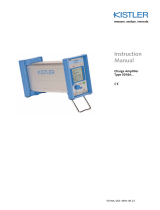
Figure 1: Handheld charge amplifier Type 5995A
3.1 Areas of application
• Servicing, assembly, commissioning (installing,
preloading)
• Field trials
• Process-integrated calibration of shunt measurements
• Quality control, acceptance testing
• Training

General description of the instrument
5995A_002-145e-08.17 Page 7
3.2 Two types of application
The instrument can be used in two ways:
• To measure mechanical measurands
Direct measurement of pressure, force, strain, torque
and acceleration in the appropriate units. To do this, set
the sensor sensitivity and required measuring range on
the instrument. The result appears directly in N, bar, g
etc.
• To measure electric charge
Instead of "mechanical units", the charge (pC) measu-
red is indicated directly.
This is useful when preloading force and strain sensors
(the preloading necessary for their installation is given in
pC) and when calibrating on site (calculation of the
sensor sensitivity as the quotient "Charge measured" /
"Actual mechanical value").
For operation, see the chapter "Assembly, installation and
initial start-up".

Handheld charge amplifier, Type 5995A…
Page 8 5995A_002-145e-08.17
4. Functional description
4.1 Introduction
The instrument Type 5995A is a single-channel, calibrated
multi-range charge amplifier with microprocessor control
and battery operation.
The parameters required can be set or read off by means of
a key pad in conjunction with an alphanumeric LCD display.
The measurement can start after the "Reset" key has been
pressed.
4.2 Menu structure
The menu structure consists of three main menus selected
with the "Menu" key.
F
i
g
u
r
e
2
:
Menu structure
• T Sensor Sensitivity [pC/M.U.]
• Sensor sensitivity in picocoulomb per mechanical unit
e.g. pC/N
• R Range [M.U.]
Measuring range in mechanical units e.g. N
• Measurement display
If the instrument is set for measurement of charge
(under unit: pC), only the following two menus are
available:
- R Range [pC]
Measuring range in picocoulomb
- Measurand display

Functional description
5995A_002-145e-08.17 Page 9
4.2.1 T Sensor sensitivity
Decimal comma shifted with s and a.
(Cursor on T)
Cursor shifted with d.
Numerical value adjusted with s and a.
4.2.2 R range (measuring range)
Range adjustment with s and a.
4.2.3 Value (measurements display)
Choice of measurand to be displayed using s and a.
Settings available for selection are:
• Max Maximum value (since last Reset)
• Inst Sample hold value
• Min Minimum value (since last Reset)
(The numeric al value appears on the top line)

Handheld charge amplifier, Type 5995A…
Page 10 5995A_002-145e-08.17
4.2.4 Unit
Shift the cursor with d.
Select the unit with s and a. The following units can be
selected: N, bar, psi, g, Nm, Ncm, με, lbs and pC.
The choice of unit has no influence on the measu-
rements, i.e. the instrument does not automatically carry
out a conversion. Always check therefore that you have
set the decimal comma correctly in the T display (sensor
sensitivity).
When you have selected pC as the value to be
measured, sensor sensitivity (T) cannot be adjusted. The
measuring result is displayed directly in pC.

Functional description
5995A_002-145e-08.17 Page 11
4.3 Block schematic diagram
Figure 3: Block schematic diagram Type 5995A
The main component of the instrument is a microprocessor
with the following functions:
• Records key pad operations
• A/D conversion, peak-value recording and signal
display
• Internal control: Reset, range switching and 12 bit
DAC (adjustable amplifier)
The charge amplifier converts the electric charge from the
sensor into a proportional voltage.
Range switching is accomplished, on the one hand, by
switching in a capacitance and, on the other hand, by means
of two series-connected amplifier stages.

Handheld charge amplifier, Type 5995A…
Page 12 5995A_002-145e-08.17
4.4 Range selection, operating range
The smallest range is ±200 pC,
the largest range is ±200'000 pC.
200 pC < R[pC] < 200'000 pC
R[pC] = T[pC/M.U.] * R[M.U.]
From which we get the adjacent operating range.
The instrument does not allow adjustments outside the
operating range, making errors impossible.
The smallest possible measuring range should always be
selected in order to keep errors as small as possible and
obtain the best possible signal-to-noise ratio.
Figure 4: Operating range

Functional description
5995A_002-145e-08.17 Page 13
4.5 Control elements
Figure 5a: View from the front
Figure 5b: View from the rear

Handheld charge amplifier, Type 5995A…
Page 14 5995A_002-145e-08.17
5. Assembly, installation and initial start-up
5.1 General notes
The input stage of the charge amplifier can be dam-
aged by too high voltage. Therefore always short- circuit
the cable (with sensor already connected!) before you
connect the amplifier. It is sufficient to touch the contact
pin of the BNC connector briefly with a paper clip, ball-
point pen etc.
The charge amplifier is designed for use in closed, dry rooms.
Protect it against moisture and dust. The instrument should
not be exposed to continuous vibration or shocks.
The instrument is supplied already calibrated and is ready to
use after inserting the battery. Use only 9 V batteries Type
IEC6LR61 or IEC6LF22.
Set the instrument to the relevant type of use by selecting the
unit:
N, bar, psi,
g, Nm, Ncm,
µε
, lbs
•
Measurement of mechanical quantities
pC
•
Measurement of electric charge
(e.g. for preloading or calibrating sensors)
5.2 Measuring mechanical quantities
• Set sensor sensitivity T (in pC/mechanical unit)
• Select measuring range R (in mechanical units)
• Select mechanical unit N, bar, psi, g, Nm, Ncm, µε, lbs
(optional)
• After "Reset" is pressed, the measurement can begin.
Pressing "Reset" establishes the zero measurand output
and resets the maximum/ minimum memory. While
"Reset" is pressed, a battery test is carried out and a
warning appears if the battery voltage is too low.
• Display can be switched between sample hold and peak
values.
• The sensor sensitivity can also be adjusted during
measurement, e.g. for calibrating the sensitivity during
measurements in force shunt mode.

Assembly, installation and initial start-up
5995A_002-145e-08.17 Page 15
5.3 Measurement of electric charge
(Preloading or calibrating sensors)
• Select pC unit.
• Select measuring range R (in pC)
• Note: T must not be set.
• After "Reset" is pressed, the measurement can begin.
Pressing "Reset" establishes the zero measurand output
and resets the maximum/ minimum memory. While
"Reset" is pressed, a battery test is carried out and a
warning appears if the battery voltage is too low.
• Display can be switched between sample hold and peak
values.
5.4 Calibrating sensors in force shunt mode
With measurements in force shunt mode, the sensor sensitivity
is not known because a large part of the force is not applied to
the sensor but to the surrounding structure.
It is therefore necessary to determine the sensor sensitivity by
calibration. The instrument allows such a calibration without
calculation, because during the measurement both the range
and sensitivity can be adjusted.
Figure 6: Calibrating force shunt measurements
1. Connect digital voltmeter to the monitor output of the
instrument
2. Press "Reset"
3. Apply force F of known value (e.g. 20'000 N)
4. Adjust measuring range R until the voltmeter indicates a
voltage in the range 0,2 ... 2 V
5. Remove force
6. Press "Reset"
7. Apply known force F once more
8. Adjust sensor sensitivity until voltmeter reads 2 V
Sshunt [pC/N] = R [N] x Sset [pC/N] / F[N]

Handheld charge amplifier, Type 5995A…
Page 16 5995A_002-145e-08.17
In this operating mode, the instrument will not indicate
over-range. If the output voltage exceeds 2 V, it will be
necessary to start again at Point 1.
After switching over the range (R), briefly press "Reset"
to eliminate any zero offsets. The sensitivity
(T) can be
adjusted during a measurement, e.g. during calibra-
tion of sensors.
5.5 Use as charge amplifier with external display unit
Figure 7: Use as charge amplifier with external display unit
It is particularly advantageous for transient or periodic
processes to plot the measurement on an oscilloscope
connected to the monitor output.
F [M.U.] = R [M.U.] x Umonitor output [V] / 2 [V]
5.6 Notes on the piezoelectric measuring method
Piezoelectric sensors (with quartz or ceramic measuring
elements) produce an electric charge as output signal. The
customary voltage or current amplifier cannot there- fore be
used, only special, so-called charge amplifiers. These convert
the charge yielded by the sensor into a proportional voltage,
which can then be further processed as normal.
High voltage (static charge) can damage the input stage of
the charge amplifier. For this reason, the cable (with sensor
already connected!) must always be short- circuited before it is
connected to the charge amplifier. To do this, simply touch the

Assembly, installation and initial start-up
5995A_002-145e-08.17 Page 17
contact pin of the connector briefly with a pointed metallic
object (paper clip, ball-point pen etc.). Sensors, and in
particular cables, can easily become electrically charged,
especially when the insulation resistance has been checked
with a teraohmmeter having higher than 10 V test voltage.
Piezoelectric sensors, cables and the charge amplifier input
must have a very high insulation resistance, for correct
measurement. The insulation resistance must be at least
1 TΩ, preferably 10 TΩ. For this reason, all connectors (sensor,
cable, charge amplifier input) must be kept scrupulously clean.
They must not be touched with the fingers. Special cleaning
agent must be used for cleaning purposes, e.g. cleaning spray
Type 1003 or pure white gasoline.
Piezoelectric sensors are inherently incapable of static
measurement over longer time. Quasistatic measurements are,
however, certainly possible, but require sufficiently high
insulation resistance in the input circuit. Too low insulation
resistance causes drift in the output signal. Cables must also be
low noise, meaning that they must not produce electric
charges during movement. For this reason, use exclusively the
special cables available from Kistler (Type No. 16xx) to
connect the sensors. Ordinary commercial cables do not meet
requirements.
Several sensors can be connected in parallel to the same
amplifier. A summation of all charges then takes place. When
all sensors have the same sensitivity, the output signal of the
charge amplifier represents the sum of all measurands.
5.7 Error messages
5.7.1 Over-range measurements
Display flashing
Select larger measuring range, press "Reset" key and repeat
measurement.
5.7.2 Battery voltage too low
When the "Reset" key is pressed, the LOW BAT message
appears
Exchange battery.
(9 V battery IEC6LR61 or IEC6LF22)
5.7.3 Calibration parameters faulty
When the instrument is switched on, the adjacent display
appears.
The instrument has lost its calibration parameters and must be
recalibrated in the factory.

Handheld charge amplifier, Type 5995A…
Page 18 5995A_002-145e-08.17
6. Maintenance
6.1 Input connector
• Protect the input connector against dirt and moisture
otherwise the insulation resistance of >10 TΩ required
will be reduced. This leads to drift of the output signal.
For cleaning, use only the cleaning sprays Type 1003 or
pure white gas 0oline.
Never attempt to measure the insulation resistance with
an insulation tester, since the input stage would then be
immediately destroyed.
• On completion of the measurement, the protective cover
must be refitted to the input connector.
6.2 Calibration
• The instrument is calibrated in the factory and the cali-
bration parameters stored in the EEPROM. Recalibra-
tion is thus only possible in the factory.
• Although the calibration data are also retained without
the battery, there is a built-in safety device to prevent
accidental operation with faulty calibration parameters.
If the following message appears when the instrument is
switched on, the instrument calibration data are
defective.
CAL.PROG
RANGE 3
The instrument will no longer operate correctly and must
be recalibrated in the factory.
/