
PC-45X(E2) Page1Texmate, Inc. Tel. (760) 598-9899
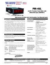
A Versatile Event Counter/Totalizer Featuring 19999 Counts with Overrange Indication, or 9999 Counts with Cascade
Output, Contact Closure or Logic Signal Input, High Contrast LCD, 4-6 V DC Powered with Outputs for User Supplied
NI-CAD Battery Back-Up, Capable of Signal Powered Operation.
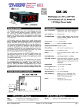
PC-45X
4 1/2 DIGIT
EVENT COUNTER
ORDERING INFORMATION
Order Part No.
STANDARD 1999 COUNTS EVENT COUNTER PC-45X
ACCESSORIES: Edge Connector (20 pin solder tabs) CN-L10
DESCRIPTION
Texmate's model PC-45X event counter/totalizer
is a versatile, low cost DC powered LCD meter which
features three user programmable count inputs and
count rates. All count inputs are compatible with open
collector sensing devices. The standard low range
SPST or SPDT dry contact closure rate is 0~6000 CPM
(0~100 CPS). The SPST switch input mode utilizes a low
pass lter and a Schmitt trigger with 15% hysteresis for
debouncing. The SPS T switch input mode which utilizes
an R-S Flip-Flop for debouncing can accept high speed
dry contact closure rates of 0~600,000 CPM (0~10,000
CPS) if the low pass lter is reduced or eliminated. The
PC-45X also accepts 3-30VDC positive going pulses
or AC signal inputs up to 15MHz. A 500mV hysteresis
aids the accurate counting of slow changing waveforms.
Other features include logic controls such as inhibit,
reset, display hold, carry output, overrange output, and
outputs to continuously trickle charge an external user
supplied Ni-Cad battery back-up which will prevent loss
of data in case of intermittent or power-out situations.
The unit is also capable of being programmed for sig-
nal powered operation. There are four programmable
decimal points, and unlimited cascading to achieve
multiples of four digits using two or more PC-45X units.
In this type of operation only the left most meter will
display a fth digit.
The display hold feature enables the user to latch
the display while the counter continues counting. With-
out affecting the latched display, the counter may be
reset to zero by the reset control or the counting function
may be stopped and started by the inhibit control. When
the Display Hold is released, the data present in the
counter at that time is instantly displayed.
With external logic control, the PC-45X may be
used as a frequency counter, RPM indicator or period
counter. The large 0.48" LCD display has excellent read-
ability in both high and low ambient light conditions,
and its low power consumption 5VDC-2mW or signal
powered operation makes it especially useful in remote
locations.
When PC-45X is programmed for signal powered
operation (9 to 600V p-p @ 400µA), the back-up bat-
tery must be used unless the input signal pulses are
continuous because power is required to maintain the
count logic.
SPECIFICATIONS
COUNT INPUTS
SPST Contact Closure: 0~6000 CPM (100Hz) with 500Hz Low Pass
lter and Schmitt Trigger set at 15%
Hysteresis
SPDT Contact Closure: 0~6000 CPM (100Hz) with 500Hz Low Pass
lter and R-S Flip-Flop. 0~600,000 CPM
(10kHz) with lter removed
3-30V AC or DC Pulse: 0~500kHz with Schmitt Trigger threshold of
2V and 500mV Hysteresis. If the internal
100kΩ overvoltage protection resistor is
removed the max count is 0~15MHz
Open Collector Sensing: All inputs are compatible with open collector
sensing devices
Over Voltage Protection: Pins 6, E & F are protected up to ±100V peak
overload with internal 100kΩ resistors.
Caution: All other input or control pins are
NOT PROTECTED against High Voltage.
CONTROLS & OUTPUTS
Reset: Dry Switch closure to ground or Logic Low "0"
input for min. 3µS resets counter to zero.
(50µA pull-up current is provided).
Inhibit Count: Dry Switch closure to ground or Logic Low "0"
input will prevent the D ip-op on the count
input from operating (10µA pull-up current is
provided)
Display Hold: An Open input or Logic High "1" input on this
pin "freezes" the display while the counter
continues to operate independently. A Dry
Switch closure to ground or Logic low "0" input
for min. 3µS updates the display (10µA pull up
current is provided.) For continuous display of
the counter input the display hold function
should be connected to ground
Carry Output: Internal solder pad SP2 provides a logic signal
ouput that occurs each 10,000 counts for cas-
cading the count in 4 digit mutilples
Overrange Output: Internal solder pad SP1 goes to Logic High "1"
when the count exceeds 20,000 counts
Display: 0.48" LCD Max. 19999
Decimal: User programmable to 4 positons
Overload Indications: All digits blank except decimal points
Back-Up Battery: 200µA output is provided to trickle charge a
user supplied 3.6V Ni-Cad battery
Power Requirements: Regulated 4VDC to 6VDC at 400µA or Signal
Powered
Operating Temperature: -20˚C to +60˚C

PC-45X(E2) Page2Texmate, Inc. Tel. (760) 598-9899
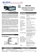
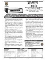
FUNCTIONAL DIAGRAM
The diagram below depicts the Model PC-45X in its standard 2V F.S. form with all
component values indicated for this mode of operation. Variations from the standard
for use in special applications will be found under the heading Typical Application
Circuits & Connection Instructions.
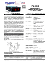
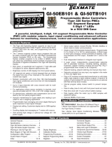
REAR VIEW OF METER CASE
The Texmate Model PC-45X interconnects by means of a stan-
dard PC board edge connector having two rows of 10 pins, spaced
on 0.156" centers. Connectors are available from Texmate, or
from almost any connector manufacturer.
CONNECTOR PINOUTS
1 - Back Plane Output
2 - Decimal Select Common
3 - Decimal Select (1.XXXX)
4 - Backup Battery Positive Terminal
5 - Inhibit Input
6 - 3-30V AC/DC Pulse Input
7 - Reset Input
8 - +5VDC System Power Input
9 - No Connection
10 - No Connection
A - Back Plane Input/Display Test
B - Decimal Select (1XXX.X)
C - Decimal Select (1XX.XX)
D - Decimal Select (1X.XXX)
E - SPDT Switch Input Enable
F - SPST/SPDT Switch Input
H - Display Hold
J - System/Power Ground Input
K - No Connection
L - No Connection
PIN DESCRIPTIONS
CAUTION: This meter employs high impedance CMOS inputs. Although
internal protection has been provided for several hundred volt overloads,
the meter will be destroyed if subjected to the high kilovolts of static dis-
charge that can be produced in low humidity environments. Always handle
the meter with ground protection.
Pin A - Back Plane input/Display Test: Pin A is connected to the display's back plane
which forms the common base of the LCD capacitance structure. Join Pin A to Back
Plane Output Pin 1 for normal operation. For Display Test connect Pin A instead to
System Ground Pin J and all operative segments will turn on. Caution: The Display
Test function is only intended for momentary operation. Continuous application of
Display Test will, in time, damage the display. SEE PAGES 5 & 6 FOR A DETAILED
EXPLANATION OF LCD OPERATION.
Pin B, C, D AND 3 - Decimal Select: Decimal points may be displayed as required by
connecting the appropiate pin to Decimal Select Common Pin 2. Any number of decimal
points can be turned on at the same time. An open circuit will turn off the decimal points.
However, static current pickup and/or PCB leakage of more than 100nA can cause
decimal points to turn on undesirably. Therefore, it is recommended that the unused
decimal points be connected to Back Plane Output Pin 1 either directly or by a resistor
of less than 5MΩ to insure an off condition. Caution: Any DC component introduced
to the display drive circuitry can, in time, cause permanent damage. PLEASE READ
PAGE 5 & 6 FOR DETAILED EXPLANATION OF LCD OPERATION.
Pin E - SPDT Switch Input Enable: To use Pin E, J10 must be opened. This creates
an R-S Flip Flop for failsafe switch closure counting. After an input is received on Pin
F, no further count inputs will be accepted until Pin E is enabled by a contact to System
Ground Pin J. When using a SPDT switch, connect the normally closed terminal to Pin
E, the normally open terminal to Pin F, and the common terminal to System Ground Pin
J. A low pass lter is provided to reject high frequency noise for operation within the
range of 0~6000 CPM (100Hz). For high speed contact closure operation, up to 10,000
counts per second max., C3 and C4 must each be reduced to 100pF or removed entirely.
Pin F - SPST/SPDT Switch Input: Connect a dry contact switch between Pin F and
System Ground Pin J or a count on contact closure rate of 0~6000 CPM (100Hz). Con-
tact debouncing is provided by a low pass lter and a Schmitt trigger factory set with a
15% Hysteresis. This standard contact closure input mode of operation is designed for
up to 100 counts per second or 6000 CMP. Faster counting rates can be implemented
by proportionally reducing the low pass lters time constant: for example, 0~200 counts
per second can be counted if C3 is changed to 5000pF. For high speed contact closure
operation, a SPDT switch must be used (see Pin E)
Pin H - Display Hold: Pin H controls a latch between the display driver circuit and
the counter circuit. For normal continuous display of the count function Pin H must
be connected to System Ground Pin J or have Logic Low "0" applied. If Pin H is left
open (a 10µA pull-up current is provided), or if Logic High "1" is applied, the display
register will latch up and hold the count displayed. The counter section will continue
independent operation and may be reset or inhibited without affecting the display hold
function. To refresh or update and hold the display, as would be required for RPM or
frequency measurement applications, pin H must be connected to System Ground
Pin J or have logic Low "0" applied for a minimum of 3µS.
Pin J - System /Power Ground Input: Negative terminal of +5VDC power should be
connected to Pin J. All digital signals, controls, outputs and back-up battery should be
returned to System/Power Ground Input Pin J. Caution: Damage may occur to the
CMOS devices in this counter if voltage inputs from external sources are applied to
the control and signal input pins before the counter's own power supply is established.
Pin K, L - No Connection: No circuit connections are made on these pins.
Pin 1 - Back Plane Output: Liquid crystal displays are operated from an AC signal.
Back Plane Output Pin 1 provides a square-wave signal of 60~160Hz that must
be connected by the user to back plane input Pin A for normal operation. Pin 1 is
internally connected to the LCD back plane which is the common base of the LCD
capacitance structure. Those segments that are driven 180° out-of-phase with the
back plane will turn on. Those segments that are driven in-phase with the back
plane will turn off. PLEASE READ PAGES 5 & 6 FOR A DETAILED EXPLANATION
OF LCD OPERATION.
PIN 2 - Decimal Select Common: Pin 2 is 180° out-of-phase with back plane
output Pin 1. Thus it serves as a common for the decimal select Pin B, C, D, and
3. To turn on any required decimal point, connect the appropriate Decimal Select
Pin to Decimal Select Common Pin 2.
Pin 4 - Backup Battery Positive Terminal: When the unit is operated from
+5VDC power, a standard 3.6V Ni-Cad battery can be used as a backup battery
by connecting the positive terminal of the battery to Pin 4 and negative to System/
Power Ground Input Pin J.
Pin 5 - Inhibit Input: For normal operation Pin 5 is left open or applied to logic
high "1" (10µA pull-up current is provided). If Pin 5 is connected to System/Power
Ground Input Pin J or has logic Low "0" applied, the count input section of the
counter circuit is disabled and will not accept input signals until Pin 5 is released
from Pin J or has Logic High "1" applied.
Pin 6 - 3-30V AC/DC Pulse Input: Pin 6 provides a direct input to the counter for
externally generated input signals. The input circuit incorporates a Schmitt Trigger
with a 2.0V threshold and 0.5V of hysteresis. A 100kΩ pull resistor R6 and a 100kΩ
overvoltage protection resistor R7 are also incorporated into the circuit. The count
occurs on the negative going edge of a positive input signal. Logic Low "0" = 0 to
+1.5V. Logic High "1" = 2.5 to +30V. The 100kΩ overvoltage protection resistor
R7 will protect the counter from overvoltages up to a peak of ± 100V. Caution:
See Pin J for precautions necessary to avoid damage to the counter from externally
generated signals. The overvoltage protection resistor limits the maximum count
speed to 0~500KHz. If the input signal is limited externally to 0~+5VDC Logic
Levels and the overvoltage protection resistor R7 is replaced with a jumper, the
counter can typically operate up to 15MHz.
Pin 7 - Reset Input: For normal accumulative counting Pin 7 is left open or applied
to Logic High "1" (50µA pull-up current is provided). When Pin 7 is connected to
System/Power Ground Input Pin J or has Logic Low"0" applied the counter will
reset to zero.
Pin 8 - +5VDC System Power Input: The regulated 4 to 6VDC, 400µA Power
Supply is connected to Pin 8. Low power consumption of 1.6 to 2.4mW enables
the meter to be operated from various power sources with simple voltage regulating
circuitry. The positive input terminal of the power supply is connected to Pin 8, the
negative terminal to System/Power Ground Input Pin J.
Pin 9, 10 - No Connection: No circuit connections are made on these pins.

PC-45X(E2) Page3Texmate, Inc. Tel. (760) 598-9899
The PC-45X may be used in a wide variety of congurations. The following circuits illustrate some of the possibilities and demonstrate the exceptional versatility of Texmate products.
Components called for in the applications which are not part of the standard meter may be supplied by the user or in some cases purchased from Texmate. The circuit diagrams
explain the basic pinout connections required for each application. Unless otherwise specied, the diagrams will show the component values and solder junctions that would normally
be installed on a standard 2V range meter. For those applications which have alternative ranges and/or input congurations, the required component values and any modications
are described in the text. NOTE: Use of these application circuits is entirely at the risk and responsibility of the user and any user modication of the meter may at the discretion of
Texmate, void the warrany. (See rear page for user's responsibility and warranty details.) The following legend applies to all application circuits: 1) optional component positions
are shown in dotted lines; 2) internal solder junctions are shown by for a closed junction or for an open junction; 3) a mechanical switch is shown by .
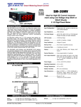
COMPONENT LAYOUT
TYPICAL APPLICATION CIRCUITS & CONNECTION INSTRUCTIONS
Cv
Cv
SOLDER SIDE
COMPONENT SIDE
OPTO-ELECTRIC COUNT INPUT
A solid-state opto-electric NPN device can be interfaced directly to
the event counter. External power maybe required to power the LED
section of the device if more than 5mA is required. Note: R1 can be
changed to match the sensitivity of the photosensor.
MOST COUNT OUTPUT DEVICES CAN BE DIRECTLY INTERFACED
Photoelectric devices, contact closure, switches, NPN open collector tran-
sistors, and voltage pulses up to 100 V can be used direclty with Model
PC-45X without expensive and complicated interfacing circuitry.
DOUBLE CONTACT CLOSURE COUNT INPUT
A mechanically coupled single pole double throw contact closure can be
used as a count input device when J10 is opened. The contact noise
debouncing circuit consists of a low-pass lter and a R-S ip-op. After a
count input is created making the connections between Pin F and Pin J, no
further count inputs will be accepted until a contact is made between Pin E
and Pin J. For higher count rates up to 0~600,000 CPM (10KHz) reduce
C3 and C4 to 2500pF or remove entirely.
COUNT INPUT WITH SINGLE CONTACT SWITCH CLOSURE
A mechanically coupled single pole single throw contact closure can
be used as a count input device for count rates up to 6000CPM
(100Hz). The contact noise debouncing circuit consists of a low-
pass lter and a Schmitt Trigger with 15% Hysteresis. If required, a
higher count rate of 0~400 Hz can be achieved by reducing C3 to 2500pF

PC-45X(E2) Page4Texmate, Inc. Tel. (760) 598-9899
3-30 AC/DC PULSE INPUT AND HIGH FREQUENCY +5VDC LOGIC
LEVEL INPUT
The input circuit incorporates a Schmitt Trigger with a 2.0V threshold
and 0.5V of hysteresis. The count occurs on the negative going edge of
an input signal. R6 acts as a pull-up resistor. R7 provides overvoltage
protection to a peak of ±100V. For 0~15MHz operation from externally
limited +5VDC logic level signals, replace R7 with a jumper.
SIGNAL POWERED OPERATION
When the PC-45X is programmed for signal powered operation (9 volts
peak-to-peak to 600 volts peak-to-peak), the input signal pulses must
be continous or the back-up battery must be used to maintain the count
logic. (See table below for changes necessary in resistance value of R7
for various peak-to-peak signal voltages.) Caution: Input signal voltages
must be limited to avoid damage to the counter when the value of R7 is
reduced below 100kΩ.
EXTERNAL LOGIC CONTROL PERMITS OPERATION AS A PERIOD
COUNTER OR REQUENCY/RPM METER
CASCADING THE UNIT
Open J5 and J8 and close J9 to disable overange indication feature. Open
J4 and jumper solder pads E & D to disable the MSD 1's to convert the rst
counter to a meter 9999 count mode. Join SP2 of the rst counter to Pin 6
of the cascading counter to provide a total of 19999~9999 counts maximum.
OFFSET AC-SIGNAL INPUT MODE
An Isolation Capacitor C, is installed externally to isolate the offset votage.
The meter is then AC coupled so that the counter can be employed to
measure an AC signal that is carried on an offset DC voltage.
TABLE FOR R7 RESISTANCE VALUE CHANGES
PEAK-TO-PEAK R7
SIGNAL INPUT VOLTAGE RESISTANCE VALUE
9- 15 Shorted
15- 25 10K
25- 50 47K
50- 90 100K
90-130 220K
130-200 330K
200-280 470K
280-600 680K
(NOTE: All voltages are peak-to-peak value and not RMS)

PC-45X(E2) Page5Texmate, Inc. Tel. (760) 598-9899
THEORY AND APPLICATION OF LIQUID CRYSTAL DISPLAYS
ELECTRICAL CHARACTERISTICS - Electrically, liquid crystal displays
function like capacitors and, unlike LED's, are driven with an AC signal.
This AC signal is necessary to maintain the electric eld required to rotate
the liquid crystal molecules. The LCD drive circuitry used for Texmate
displays puts out a 60Hz square wave signal which is truly symmetrical and
contains no DC components. Fig. 3 shows the typical AC drive signal's
relationship between the common back plane and the individual segment
elements. A segment is turned on when its drive signal is 180° out of
phase with respect to the back plane. A segment is turned off when its
drive signal is in phase with the back plane so that there is no net voltage
between the back plane and the segment. Fig. 4 explains operation of he
internal logic circuitry used to create the AC drive signal described in Fig. 3.
The eld-effect liquid crystal display is the most advanced and reliable
liquid crystal display available today. Its operation depends on changing
the optical properties of the liquid crystal by applying an electric eld.
The effect of this change is in turn, made visible by polarizers placed on
each side of the display cell.
TEMPERATURE SPECIFICATIONS - The extremely pure state-of-the-art
LC materials used in Texmate displays provide a wide operating tempera-
ture range of -10°C to +60°C and a storage temperature range of -30°C to
+70°C. Maintaining the display at temperatures above 70°C for sustained
periods (days), or above 100°C for shorter times (minutes) can cause
permanent damage ot the LC material and/or polarizing lm. At the low
end of the temperature range, there is no xed breakdown temperature.
Instead, the display response time increases as molecular movement is
slowed down due to the increased viscosity of the LC uid. At approximate-
ly -15 to -20°C the LC compound undergoes rst- or second-order phase
changes and ceases to operate. Such changes, however, are reversible
and not damaging. For example, LCD'S immersed in liquid nitrogen have
returned to normal operation after a brief warmup period.
CAUTION - If a DC component is introduced into the display, electrolysis
occurs and the transparent conductors which form the individual display
elements will, in time, be destroyed. A DC component can be created by
leakage or inadvertent connection to system ground of unused display
elements such as decriptors and decimal points. For this reason it is
recommended that unused display elements be connected to to the back
plane output drive pin which is provided on all Texmate LCD meters. The
back plane signal will then drive these unused elements to an off condition.
Short term application of a DC signal will not damage the display and ,
in fact, the display test function in most Texmate meters utilizes a DC
signal to light up all segments for test purposes. This function, however,
is only intended for momentary usage and if left activated for longer than
24 hours, damage to the display will occur.
Liquid crystal displays are inherently reliable and thousands of Texmate's
proprietary, customized LCD displays have been in continuous use
throughout the world often in harsh environmental conditions for many
years. An understanding of the simple precautions outlined here will
provide many years of reliable maintenance-free use.
DISPLAY CONSTRUCTION AND OPERATION - The best description of
liquid crystal is that is an ordered uid of a class called nematic. Nematic
uids of the type used for liquid crystal displays consist of cigar-shaped
organic molecules with the long axis of each molecule pointing in the same
direction. The display cell is constructed from two pieces of glass coated
on the inner side with transparent indium oxide conductors, as shown
in Fig.1. Each of the transparent conductors on the inside of the larger
rear glass piece is shaped to form the individual segments of the display
and are terminiated on individual contact pads. The single conductor on
the inside of the front glass piece is shaped so as to be common to all
the segments on the rear glass. Traditionally this common conductor
is usually referred to as the "back plane". The common back plane is
connected to the two left most (viewed from the front) contact pads by a
small dot of conductive epoxy imbedded in the spacer/seal. The glass
surfaces are also specially treated to align the liquid crystal molecules in a
partiular direction. Alignment is parallel to the plane of the glass, with the
alignment direction of the top rotated 90° relative to the alignment of the
bottom plate. This causes the cigar-shaped liquid crystal molecules in the
cell to assume a twisted orientation, when viewed from top to bottom. As
shown in Fig. 2, the plane of polarization of polarized light will follow this
twist and emerge from the cell rotated 90°. Thus, when the cell is placed
between crossed polarizers, the polarizers will transmit light. When an
electric eld is applied to the transparent conductors on the inside of the
glass cell, the liquid crystal molecules will physically move and reorient
themselves parallel to the eld. The 90° twist is then destroyed, and that
portion of the cell between the conductors will appear dark. Conversely,
when the cell is placed between parallel polarizers light cannot be trans-
mitted and the entire display will appear dark. When the electric eld is
then applied the segments formed by the transparent conductors will then
appear light against a dark ground.
FIGURE 1. LCD Cross-Section
FIGURE 2. LCD Operating Pinciples
FIGURE 4. Exclusive-Or Drive Circuit
FIGURE 3. Typical AC Drive Signals

PC-45X(E2) Page6Texmate, Inc. Tel. (760) 598-9899
THEORY AND APPLICATION OF LIQUID CRYSTAL DISPLAYS (CONTINUED)
FIGURE 5. Replaceable Polarizers & Reector Assembly
HUMIDITY SPECIFICATIONS - The polarized lm used in LCD
displays can be damaged by combinations of high temperature
and high humidity, i.e., 85% RH at 50˚C for 96 hours. Although
these extreme conditions are rarely encountered in actual use.
Texmate has provided for easy removal and replacement of
polarizers and reectors (see Fig. 5). The front polarizer is a
loose piece and the combination rear polarizer and reector can
be slid out from the space between the LCD and the PC board.
Spare replacement polarizers are available from Texmate. The
polarizers normally provided with the meter as standard provide
a reective display mode. That is the background appears
white and the segments appear black. Substitute rear polarizer/
reectors can be ordered with the opposite polarization plane.
This will cause the display to become transmissive, with a black
foreground and white segments. The polarization plane of the
front polarizer is never changed from horizontal because al-
though to the naked eye the display would operate perfectly if it
were changed, a person viewing the display through polarized
sunglasses would be unable to read any segments as the entire
display would appear black.
WARRANTY
Texmate warrants that its products are free from defects in material and workmanship under
normal use and service for a period of one year from date of shipment. Texmate’s obligations
under this warranty are limited to replacement or repair, at its option, at its factory, of any of
the products which shall, within the applicable period after shipment, be returned to Texmate’s
facility, transportation charges pre-paid, and which are, after examination, disclosed to the sat-
isfaction of Texmate to be thus defective. The warranty shall not apply to any equipment which
shall have been repaired or altered, except by Texmate, or which shall have been subjected
to misuse, negligence, or accident. In no case shall Texmate’s liability exceed the original pur-
chase price. The aforementioned provisions do not extend the original warranty period of any
product which has been either repaired or replaced by Texmate.
USER’S RESPONSIBILITY
We are pleased to offer suggestions on the use of our various products either by way of printed
matter or through direct contact with our sales/application engineering staff. However, since
we have no control over the use of our products once they are shipped, NO WARRANTY
WHETHER OF MERCHANTABILITY, FITNESS FOR PURPOSE, OR OTHERWISE is made
beyond the repair, replacement, or refund of purchase price at the sole discretion of Texmate.
Users shall determine the suitability of the product for the intended application before using,
and the users assume all risk and liability whatsoever in connection therewith, regardless
of any of our suggestions or statements as to application or construction. In no event shall
Texmate’s liability, in law or otherwise, be in excess of the purchase price of the product.
Texmate cannot assume responsibility for any circuitry described. No circuit patent or software
licenses are implied. Texmate reserves the right to change circuitry, operating software, speci-
fications, and prices without notice at any time.
Copyright © 2023 Texmate Inc. All Right Reserved.
PC-45X Technical Manual Copyright © 2023 Texmate Inc. All rights reserved.
Published by: Texmate Inc. USA. Information in this Technical Manual is
subject to change without notice due to correction or enhancement. The in-
formation described in this manual is proprietary to Texmate, Inc. and may
not be copied, reproduced or transmitted, in whole or in part, in connection
with the design, manufacture, or sale of apparatus, device or private label
product without the express written consent of Texmate, Inc.
1934 Kellogg Ave., Carlsbad, CA 92008
Tel: 1-760-598-9899 • 1-800-TEXMATE • Email: orders@texmate.com
Case Dimensions
TOP VIEW
FRONT VIEW
PANEL CUTOUT SIDE VIEW
16.82mm
0.662in
29.60mm
1.165in
14.50mm
0.571in
64.77mm
2.550 in
24.64mm
0.970in
69.90mm
2.752in
option metal
screw mounting clip
102.36mm
4.030in
84.50mm
3.330in
Edge connector
When extra panel mounting
tightness is required, optional
Screw Mounting Clips can be
purchased seperately and attach
to the sliding mounting side clips
8.50mm
0.335in
2.50mm
0.098in
Case Dimensions and Panel Cutouts
-
 1
1
-
 2
2
-
 3
3
-
 4
4
-
 5
5
-
 6
6


Ask a question and I''ll find the answer in the document
Finding information in a document is now easier with AI
Related papers
-
 Texmate PM-45L Owner's manual
-
 Texmate SM-35X Owner's manual
-
 Texmate PM-35U Owner's manual
-
 Texmate RP-3500D2 Owner's manual
-
 Texmate RP-4500D2 Owner's manual
-
 Texmate SM-35MV Owner's manual
-
 Texmate SM-35 Owner's manual
-
 Texmate BI-60A Owner's manual
-
 Texmate GI-50EB101 Owner's manual
-
 Texmate DI-60AT5C Owner's manual


