Page is loading ...

User's guide
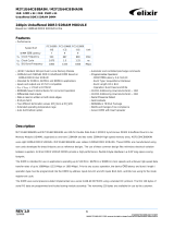
CB59
CB62
•Feedback encoder series for servo and gearless motors
•2,048 PPR sine/cosine output + CD track for rotor position
•CB59: Ø 12.7-mm (1/2”) and 15-mm (0.59”) hollow shaft
•CB62: Ø 10-mm (0.39”) 1:10 tapered solid shaft
•Many mounting options (expansion flange and fixing plates)
Suitable for the following models:
•CB59
•CB62
General Contents
1 - Safety summary 6
2 - Identification 7
3 - Mounting instructions 8
4 - Electrical connections 15
5 - Output signals 18
Smart encoders & actuators

This publication was produced by Lika Electronic s.r.l. 2020. All rights reserved. Tutti i diritti riservati. Alle Rechte vorbehalten. Todos los
derechos reservados. Tous droits réservés.
This document and information contained herein are the property of Lika Electronic s.r.l. and shall not be reproduced in whole or in
part without prior written approval of Lika Electronic s.r.l. Translation, reproduction and total or partial modification (photostat copies,
film and microfilm included and any other means) are forbidden without written authorisation of Lika Electronic s.r.l.
The information herein is subject to change without notice and should not be construed as a commitment by Lika Electronic s.r.l. Lika
Electronic s.r.l. reserves the right to make all modifications at any moments and without forewarning.
This manual is periodically reviewed and revised. As required we suggest checking if a new or updated edition of this document is
available at Lika Electronic s.r.l.'s website. Lika Electronic s.r.l. assumes no responsibility for any errors or omissions in this document.
Critical evaluation of this manual by the user is welcomed. Your comments assist us in preparation of future documentation, in order
to make it as clear and complete as possible. Please send an e-mail to the following address [email protected] for submitting your
comments, suggestions and criticisms.

General contents
User's guide......................................................................................................................................................... 1
General contents............................................................................................................................................. 3
Typographic and iconographic conventions.............................................................................................4
Preliminary information................................................................................................................................ 5
1 - Safety summary....................................................................................................................................... 6
1.1 Safety..........................................................................................................................................................................................6
1.2 Electrical safety.......................................................................................................................................................................6
1.3 Mechanical safety..................................................................................................................................................................6
2 - Identification............................................................................................................................................ 7
3 - Mounting instructions............................................................................................................................ 8
3.1 CB59 encumbrance sizes....................................................................................................................................................8
3.1.1 Installing the CB59 encoder............................................................................................................. 8
3.1.2 Dismounting the CB59 encoder......................................................................................................9
3.2 CB62 encumbrance sizes (standard version)...........................................................................................................10
3.2.1 Installing the CB62 encoder (standard version)...........................................................................10
3.2.2 Dismounting the CB62 encoder (standard version).....................................................................11
3.3 CB62 encumbrance sizes (A order code)...................................................................................................................12
3.4 CB62 encumbrance sizes (B order code)...................................................................................................................12
3.5 CB62 encumbrance sizes (D order code)...................................................................................................................13
3.6 CB62 encumbrance sizes (E order code)...................................................................................................................13
3.6.1 Mounting the CB62 encoder (A, B, D and E order codes)...........................................................13
3.6.2 Dismounting the CB62 encoder (A, B, D and E order codes)......................................................14
4 - Electrical connections........................................................................................................................... 15
4.1 98414-G05-14-LF 14-pin connector..........................................................................................................................16
4.2 EC-ASB/CB62-xx connection cable.............................................................................................................................16
4.3 TF12 connection cable specifications.........................................................................................................................16
4.4 Cable shield connection to ground.............................................................................................................................17
5 - Output signals........................................................................................................................................ 18
5.1 Output signals level............................................................................................................................................................19

Typographic and iconographic conventions
In this guide, to make it easier to understand and read the text the following typographic and
iconographic conventions are used:
•parameters and objects both of the device and the interface are coloured in GREEN;
•alarms are coloured in RED;
•states are coloured in FUCSIA.
When scrolling through the text some icons can be found on the side of the page: they are expressly
designed to highlight the parts of the text which are of great interest and significance for the user.
Sometimes they are used to warn against dangers or potential sources of danger arising from the use of
the device. You are advised to follow strictly the instructions given in this guide in order to guarantee
the safety of the user and ensure the performance of the device. In this guide the following symbols are
used:
This icon, followed by the word WARNING, is meant to highlight the parts of the
text where information of great significance for the user can be found: user must
pay the greatest attention to them! Instructions must be followed strictly in order
to guarantee the safety of the user and a correct use of the device. Failure to heed
a warning or comply with instructions could lead to personal injury and/or damage
to the unit or other equipment.
This icon, followed by the word NOTE, is meant to highlight the parts of the text
where important notes needful for a correct and reliable use of the device can be
found. User must pay attention to them! Failure to comply with instructions could
cause the equipment to be set wrongly: hence a faulty and improper working of
the device could be the consequence.
This icon is meant to highlight the parts of the text where suggestions useful for
making it easier to set the device and optimize performance and reliability can be
found. Sometimes this symbol is followed by the word EXAMPLE when instructions
for setting parameters are accompanied by examples to clarify the explanation.

Preliminary information
This guide is designed to provide the most complete information the operator needs to correctly and
safely install and operate CB59 and CB62 encoders. It further describes the EC-ASB/CB62-xx
connection cable.
CB59 and CB62 encoders are engineered to deliver feedback signals to know both position and speed of
servo motors and gearless motors. In addition to sine/cosine 1Vpp signals, an absolute signal (CD
absolute track) is generated to provide information about the position of the motor poles needful at
motor start-up.
For technical specifications please refer to the product datasheet.

CB59 • CB62
1 - Safety summary
1.1 Safety
Always adhere to the professional safety and accident prevention regulations
applicable to your country during device installation and operation;
installation and maintenance operations have to be carried out by qualified
personnel only, with power supply disconnected and stationary mechanical
parts;
device must be used only for the purpose appropriate to its design: use for
purposes other than those for which it has been designed could result in
serious personal and/or the environment damage;
high current, voltage and moving mechanical parts can cause serious or fatal
injury;
warning ! Do not use in explosive or flammable areas;
failure to comply with these precautions or with specific warnings elsewhere
in this manual violates safety standards of design, manufacture, and
intended use of the equipment;
Lika Electronic assumes no liability for the customer's failure to comply with
these requirements.
1.2 Electrical safety
Turn OFF the power supply before connecting the device;
connect according to the explanation in the ”4 - Electrical connections”
section on page 15;
wires of output signals which are not used must be insulated singularly;
in compliance with 2014/30/EU norm on electromagnetic
compatibility, following precautions must be taken:
- before handling and installing the equipment, discharge electrical
charge from your body and tools which may come in touch with the device;
- power supply must be stabilized without noise; install EMC filters on device
power supply if needed;
- we suggest using the connection cable code EC-ASB/CB62-xx (on request);
- avoid cables runs longer than necessary;
- avoid running the signal cable near high voltage power cables;
- mount the device as far as possible from any capacitive or inductive noise
source; shield the device from noise source if needed;
- minimize noise by connecting to ground (GND) the cable shield or the device
housing. Make sure that ground (GND) is not affected by noise. The shield
connection point to ground can be situated both on the device side and on
user’s side. The best solution to minimize interference must be carried out by
the user.
1.3 Mechanical safety
Install the device following strictly the information in the “3 - Mounting
instructions” section on page 8;
mechanical installation has to be carried out with stationary mechanical
parts;
do not disassemble the device;
do not tool the device;
MAN CB59_CB62 E 1.17.odt 1 - Safety summary 6 of 20

CB59 • CB62
delicate equipment: handle with care; do not subject the device to knocks or
shocks;
respect the environmental characteristics declared by the manufacturer.
2 - Identification
Device can be identified through the order code and the serial number printed
on the label applied to its body. Information is listed in the delivery document
too. Please always quote the order code and the serial number when reaching
Lika Electronic. For any information on the technical characteristics of the
product refer to the technical catalogue.
Warning: encoders having order code ending with "/Sxxx" may have
mechanical and electrical characteristics different from standard and
be supplied with additional documentation for special connections
(Technical Info).
MAN CB59_CB62 E 1.17.odt 2 - Identification 7 of 20

CB59 • CB62
3 - Mounting instructions
WARNING
Installation and maintenance operations must be carried out by qualified
personnel only, with power supply disconnected and mechanical parts
absolutely in stop. Do not tool the unit.
3.1 CB59 encumbrance sizes
(values are expressed in mm)
Figure 1 - CB59 encumbrance sizes
3.1.1 Installing the CB59 encoder
For correct installation the motor shaft must be fitted with an M5-threaded
bore (see Figures below).
To install the encoder please follow carefully the next steps:
remove the PG cap 1 from the back of the encoder;
fit the encoder into the rotor shaft 2 and fix it using the provided M5 x 10
UNI 5931 screw 3; the recommended tightening torque is 5 Nm;
Figure 2 - Mounting of CB59 encoder
MAN CB59_CB62 E 1.17.odt 3 - Mounting instructions 8 of 20

CB59 • CB62
replace the PG cap 1 properly and tighten it;
fasten the fixing plate 4 to the motor frame using two M3 screws 5.
Figure 3 - CB59 installation tolerances
3.1.2 Dismounting the CB59 encoder
To dismount the encoder please follow carefully the steps described hereinafter:
unscrew the fixing plate 4 from the motor frame;
remove the PG cap 1 from the back of the encoder;
hold the rotor shaft 2 and screw off the M5 screw 3 which fixes the encoder
shaft to the rotor shaft 2.
WARNING: do not force the encoder manually to pull it out!
ensure that the rotor shaft 2 does not move and carefully tighten an M6
screw instead of the M5 screw in the encoder shaft: tightening the M6
screw will cause the encoder shaft to be drawn out slowly. To prevent the
thread of the rotor shaft 2 from being damaged we suggest tightening an
M5 grub screw before screwing in the M6 screw.
MAN CB59_CB62 E 1.17.odt 3 - Mounting instructions 9 of 20

CB59 • CB62
3.2 CB62 encumbrance sizes (standard version)
(values are expressed in mm)
Figure 4 - CB62 encumbrance sizes (standard version)
3.2.1 Installing the CB62 encoder (standard version)
For correct installation the motor shaft must be fitted with an M5-threaded
bore (see Figures below).
To install the encoder please follow carefully the next steps:
remove the PG cap 1 from the back of the encoder;
fit the encoder into the rotor shaft 2 and fix it using the provided M5 x 50
UNI 5931 screw 3; the recommended tightening torque is 5 Nm;
replace the PG cap 1 properly and tighten it;
tighten the M3 screw 4 to cause the flange 5 to expand so clamping the
encoder onto the stator 6; the recommended tightening torque is 1.2 Nm.
Figure 5 - Mounting of CB62 encoder (standard version)
MAN CB59_CB62 E 1.17.odt 3 - Mounting instructions 10 of 20

CB59 • CB62
Figure 6 - CB62 installation tolerances (standard version)
3.2.2 Dismounting the CB62 encoder (standard version)
To dismount the encoder please follow carefully the steps described hereinafter:
unscrew the M3 screw 4 to release the expansion flange 5;
remove the PG cap 1 from the back of the encoder;
hold the rotor shaft 2 and screw off the M5 screw 3 which fixes the encoder
shaft to the rotor shaft 2.
WARNING: do not force the encoder manually to pull it out!
ensure that the rotor shaft 2 does not move and carefully tighten an M6
screw instead of the M5 screw in the encoder shaft: tightening the M6
screw will cause the encoder shaft to be drawn out slowly. To prevent the
thread of the rotor shaft 2 from being damaged we suggest tightening an
M5 grub screw before screwing in the M6 screw.
MAN CB59_CB62 E 1.17.odt 3 - Mounting instructions 11 of 20

CB59 • CB62
3.3 CB62 encumbrance sizes (A order code)
(values are expressed in mm)
Figure 7 - CB62 encumbrance sizes (A order code)
3.4 CB62 encumbrance sizes (B order code)
(values are expressed in mm)
Figure 8 - CB62 encumbrance sizes (B order code)
MAN CB59_CB62 E 1.17.odt 3 - Mounting instructions 12 of 20

CB59 • CB62
3.5 CB62 encumbrance sizes (D order code)
(values are expressed in mm)
Figure 9 - CB62 encumbrance sizes (D order code)
3.6 CB62 encumbrance sizes (E order code)
(values are expressed in mm)
Figure 10 - CB62 encumbrance sizes (E order code)
3.6.1 Mounting the CB62 encoder (A, B, D and E order codes)
For correct installation the motor shaft must be fitted with an M5-threaded
bore (see Figures above).
To install the encoder please follow carefully the next steps:
remove the PG cap 1 from the back of the encoder;
MAN CB59_CB62 E 1.17.odt 3 - Mounting instructions 13 of 20

CB59 • CB62
fit the encoder into the rotor shaft 2 and fix it using the provided M5 x 50
UNI 5931 screw 3; the recommended tightening torque is 5 Nm;
replace the PG cap 1 properly and tighten it;
B, D and E order codes only: fasten the fixing plate 4 to the motor frame
using two appropriate screws 5: M3 x 5 min. for B and E order codes,
recommended tightening torque = 1.2 Nm; M4 x 5 min. for D order code,
recommended tightening torque = 2.8 Nm.
Figure 11 - Example with B type fixing plate
3.6.2 Dismounting the CB62 encoder (A, B, D and E order codes)
To dismount the encoder please follow carefully the steps described hereinafter:
B, D and E order codes only: unscrew the fixing plate 4 from the motor
frame;
remove the PG cap 1 from the back of the encoder;
hold the rotor shaft 2 and screw off the M5 screw 3 which fixes the encoder
shaft to the rotor shaft 2.
WARNING: do not force the encoder manually to pull it out!
ensure that the rotor shaft 2 does not move and carefully tighten an M6
screw instead of the M5 screw in the encoder shaft: tightening the M6
screw will cause the encoder shaft to be drawn out slowly. To prevent the
thread of the rotor shaft 2 from being damaged we suggest tightening an
M5 grub screw before screwing in the M6 screw.
MAN CB59_CB62 E 1.17.odt 3 - Mounting instructions 14 of 20

CB59 • CB62
4 - Electrical connections
WARNING
Power supply must be turned off before performing any electrical connection!
If wires of unused signals come in contact, irreparable damage could be caused
to the device. Thus they must be cut at different lengths and insulated
singularly.
Function 14-pin connector TF12 cable
C * 1 Violet
A3 Red
/D * 4 Pink
0Vdc 5 White_Green
/B 6 Brown
07 White
/0 8 Blue
B9 Green
D * 11 Grey
/A 12 Black
+5Vdc ±5% 13 Brown_Green
/C * 14 Yellow
not connected 2, 10 -
Shield Shield Shield
* C / D signals of the absolute track are provided with option /1 only, see the
order code
A, B signals: Incremental sine/cosine signals, 2,048 pulses at each complete
turn of the encoder shaft.
C, D signals: Absolute sine/cosine track, 1 sinusoidal period at each complete
turn of the encoder shaft.
WARNING
C / D signals of the absolute track are provided with option /1 only, see the
order code
0 signal: Index "Z-track", 1 pulse at each complete turn of the encoder
shaft.
For complete information about the signals please refer to the “5 - Output
signals” section on page 18.
MAN CB59_CB62 E 1.17.odt 4 - Electrical connections 15 of 20

CB59 • CB62
4.1 98414-G05-14-LF 14-pin connector
14-pin male connector
Female mating connector: SQW-107-01-F-D-VS
4.2 EC-ASB/CB62-xx connection cable
The encoder can be supplied with a connection cable order code EC-
ASB/CB62-xx where xx is the length of the cable. Refer to the order code for
the available cable lengths. The connection cable must be ordered separately.
4.3 TF12 connection cable specifications
Model : LIKA TF12 encoder cable
Cross section : 6 x 2 x 28AWG
Jacket : Special flame retardant PVC compound, RZ-TM2 quality
Shield : Tinned copper braid, coverage > 80% with tinned copper
drain wire
Outer diameter : 5.4 mm ±0.1 mm (0.213” ±0.004”)
Min. bending radius : outer diameter x 10
Work temperature : -15°C +80°C (+5°F +176°F)
Conductor resistance : < 242.02 /Km (+20°C / -4°F)
(UL 758 table 5.2.1)
The total length of the cable that connects the encoder and the receiving device
should not exceed the values stated in the “Cable lengths” section of the rotary
encoders' catalogue or indicated in this manual; they are specific for each type
of output circuit. If you need to reach greater distances please contact Lika
Electronic Technical Dept.
MAN CB59_CB62 E 1.17.odt 4 - Electrical connections 16 of 20

CB59 • CB62
4.4 Cable shield connection to ground
To connect the cable shield we suggest gathering the shielding wires together
and fixing them by means of a hexagonal metal gland crimped 25 mm / 0.984”
away from the connector. Be sure that the gland is in tight contact with the
encoder's enclosure. Prevent the shielding wires from coming in contact with
the internal electronics.
MAN CB59_CB62 E 1.17.odt 4 - Electrical connections 17 of 20

CB59 • CB62
5 - Output signals
The frequency of the output signals is proportional to the shaft rotational speed.
As “Resolution (PPR)” is 2048/x (see the order code), then the encoder provides
2,048 A and B sinusoidal pulses + Z track single pulse at each revolution.
The encoder provides C and D absolute sinusoidal signals at each turn (absolute
track) only if “Resolution (PPR)” is 2048/1 (see the order code).
MAN CB59_CB62 E 1.17.odt 5 - Output signals 18 of 20

CB59 • CB62
5.1 Output signals level
The voltage level refers to the differential value between normal and inverted
signal (differential).
Recommended input circuit
Sensor Input circuit
VREF = 2.5V ± 0.5V VA = 1Vpp * Av Av = R2 / R1
MAN CB59_CB62 E 1.17.odt 5 - Output signals 19 of 20

Document release Release date Description HW SW Interface
1.0 06.11.2006 First issue - - -
... ... ... ... ... ...
1.14 21.09.2016 14-pin connector information added - - -
1.15 27.10.2017 CB62 model information added, CB61 model
information removed - - -
1.16 18.12.2019 New connection cable - - -
1.17 30.11.2020
CB60 model information removed, information
about new mounting options of CB62 added (order
codes A, B, D, E)
- - -
This device is to be supplied by a Class 2 Circuit or Low-Voltage
Limited Energy or Energy Source not exceeding 30 Vdc. Refer to the
order code for supply voltage rate.
Ce dispositif doit être alimenté par un circuit de Classe 2 ou à très
basse tension ou bien en appliquant une tension maxi de 30Vcc. Voir
le code de commande pour la tension d'alimentation.
Lika Electronic
Via S. Lorenzo, 25 • 36010 Carrè (VI) • Italy
Tel. +39 0445 806600
Fax +39 0445 806699
[email protected] • www.lika.biz
/